
Close-coupled nozzle atomization integral simulation and powder preparation using vacuum induction gas atomization technology∗
2021-03-11 08:33PengWang汪鹏JingLi李静XinWang王欣HengSanLiu刘恒三BinFan范斌PingGan甘萍RuiFengGuo郭瑞峰XueYuanGe葛学元andMiaoHuiWang王淼辉
Chinese Physics B 2021年2期
Peng Wang(汪鹏), Jing Li(李静),†, Xin Wang(王欣), Heng-San Liu(刘恒三), Bin Fan(范斌),Ping Gan(甘萍), Rui-Feng Guo(郭瑞峰), Xue-Yuan Ge(葛学元),‡, and Miao-Hui Wang(王淼辉),§
1Beijing National Innovation Institute of Lightweight Ltd.,Beijing 100083,China
2State Key Laboratory for Advanced Forming Technology and Equipment,China Academy of Machinery and Technology,Beijing 100083,China
3School of Materials Science and Engineering,University of Science and Technology Beijing,Beijing 100083,China
Keywords: metallic powder,close-coupled nozzle,two-phase,droplet morphology
1. Introduction
The rapid development of powder fabrication technology has expanded the application horizon of metallic powders,especially in the areas of three-dimensional (3D) printing and powder metallurgy.[1–4]Therefore, a large number of fabrication processes, such as electrode induction melting gas atomization (EIGA), plasma atomization (PA), plasma rotating electrode atomization process (PREP) and vacuum induction gas atomization(VIGA)process,have been developed to produce spherical metallic powders.[5,6]EIGA,PA and PREP processes are mostly used to prepare high-reactive metallic powders, such as titanium and superalloy powder,[7]while the VIGA process is usually used to prepare low-reactive metallic powders such as copper alloys,aluminum alloys,and stainless steels.[8]The vacuum induction gas atomization is considered as a promising powder fabrication route because of its distinct advantages, such as high sphericity, controllable powder particle size, low oxygen content and low production cost.[9,10]The gas atomization utilizes a high-speed cold gas stream to exchange a large amount of heat and kinetic energy to a high-temperature metal stream, resulting in atomized metallic droplets, which rapidly solidify to form metal powders without significant segregation.[11]During this process, the nozzle structure plays a critical role in the atomization process and determines the diameter and sphericity of the atomized metallic powder.At present,the mainstream atomizing nozzles mainly include free-fall nozzles and close-coupled nozzles. In general, the close-coupled nozzles are preferred due to their high atomization efficiency and capability of producing fine powder particles.[12,13]
The gas atomization of the close-coupled nozzle is carried out in a closed furnace, so it is difficult to study it with conventional experimental methods. For this reason, ¨Unal et al.[14]used high-speed photography technology to study the liquid breakage of fine aluminum powder prepared by closecoupled nozzles during vacuum induction gas atomization.Ting et al.[15]used the discrete Fourier transform(DFT)algorithm to analyze the high-speed photographic lens recorded of the process for preparing 304 stainless steel powder of gas atomization by the National Institute of Standards and Technology(NIST).Hernandez et al.[16]used schlieren technology to study the airflow field structure of close-coupled nozzle.However,the conditions required for these experiments are difficult to meet in most laboratories, and the realization is very difficult.
To address the difficulties of experimental research methods,with the gradual development of computational fluid dynamics (CFD) software and algorithms, most researchers began to use fluid simulation to conduct theoretical research on the nozzle atomization process and mechanism. The atomization process of the close-coupled nozzle is mainly divided into the primary atomization process, in which the metallic liquid flow is broken into droplets, and the secondary atomization process, in which the droplets continue to be broken.[17]Zeoli et al.[18,19]simulated the primary atomization process for different types of atomizer in three dimensions by volume-offluid (VOF) multiphase flow using the Euler method. Zhao et al.[20]simplified the geometric model of three-dimensional(3D) symmetric close-coupled nozzles into two-dimensional(2D) axisymmetric form to simulate the primary atomization process, whereas the droplet breaking process did not occur as expected. Arachchilage et al.[21]studied the influence of gas pressure on droplet diameter distribution at a threedimensional scale by the VOF method,which reproduced the fragmentation of the metallic liquid flow.Most of these studies focused on the influence of close-coupled nozzle atomization process parameters or geometry on atomization. However,the detailed metallic liquid flow or single droplet atomization deformation process and the atomized droplet morphology of the close-coupled nozzle have not been studied. In addition, due to the limitation of computing resources,it is difficult to simulate the integral atomization process of the metallic liquid flow by using the VOF method,and the number of broken droplets captured by this method is limited,so it is hard to predict the powder diameter after secondary atomization.
To further realize the prediction of powder diameter after secondary atomization. Some researchers have begun to ignore primary atomization process,using the Euler–Lagrangian method and the droplet instability breaking model to simulate the powder diameter distribution after the second atomization for the close-coupled nozzle. Zeoli et al.[22]and Firmansyah et al.[23]ignored the primary atomization and utilized Taylor analogy break-up (TAB) and Kelvin–Helmholtz (KH)instability break-up models to investigate the nozzle droplet atomization and solidification process. Thompson et al.[24]demonstrated that the Kelvin–Helmholtz Rayleigh-transport(KH-RT)break-up model could be utilized to predict the particle size distribution of close-coupled nozzles. Kaiser et al.[25]employed the KH instability break-up model to simulate the interaction between gas shock wave and metallic melt.The results revealed that the shock wave structure is unfavorable for the refined powder. However, this method requires a certain simplification of the primary atomization result of the VOF model simulation as the initial condition of the secondary atomization simulation,which will bring a large deviation in the secondary atomization simulation.
In this work,the VOF multiphase flow model is employed to simulate the 316L stainless steel metallic flow atomization process for close-coupled annular nozzle. Moreover, the formation of droplets via metal-liquid flow tearing and breaking by a close-coupled atomizer at a three-dimensional scale is described in detail, which includes primary atomization and initialization of secondary atomization processes. In addition,the secondary atomization of the droplets is simulated, using the VOF-Lagrangian method to integrally predict the powder diameter distribution, while the prediction of the atomized droplet morphology after the secondary atomization of a single ellipsoidal droplet is also simulated using the VOF model. We use MATLAB (FPsize3D) to extract the atomized droplet information simulated by the VOF model. Furthermore,the forming relationship between the typical droplet shape and the powder morphology is analyzed. Herein, the numerical simulations are mainly based on commercial CFD software, i.e., Fluent19.2, which employs the finite volume method (FVM) to solve the governing equations, using transient calculations to simulate metallic liquid atomization process,prediction powder diameter and droplet morphology for close-coupled ring slit nozzle.
2. Experimental and numerical methods
2.1. Experimental method
Figure 1(a) shows the VIGA powder preparation equipment independently developed by our group. The key components of the equipment mainly include melting room,smelting crucible,insulation crucible,atomization tower,close-coupled nozzle and powder collector. The smelting crucible capacity of the equipment is 100 kg, the highest melting temperature is 1973 K, the highest insulation temperature of the middle insulation crucible is 1573 K, and the ultimate vacuum degree in the atomization tower is 8×10⁻³Pa. The preparation of 316L stainless steel metal powder uses nitrogen as the atomizing gas, the inlet pressure is 2.5 MPa, the temperature is 300 K, the smelting crucible is heated to 1700 K for casting and atomization, and the intermediate holding crucible is heated to 1523 K. During the atomization process, the melting room containing the smelting crucible is pressurized to 20 kPa, while the atomization tower is reduced to −10 kPa under the action of the vacuum pump. The process of atomization of metallic liquid flow into fine powder mainly includes the primary atomization,secondary atomization and the solidification of the droplets,as shown in Fig.1(b). The BT-9300S laser particle size analyzer is used to measure the particle size of the powder. The surface morphology of the 316L stainless steel powder was examined using a scanning electron microscope(SEM,GeminiSEM 500).
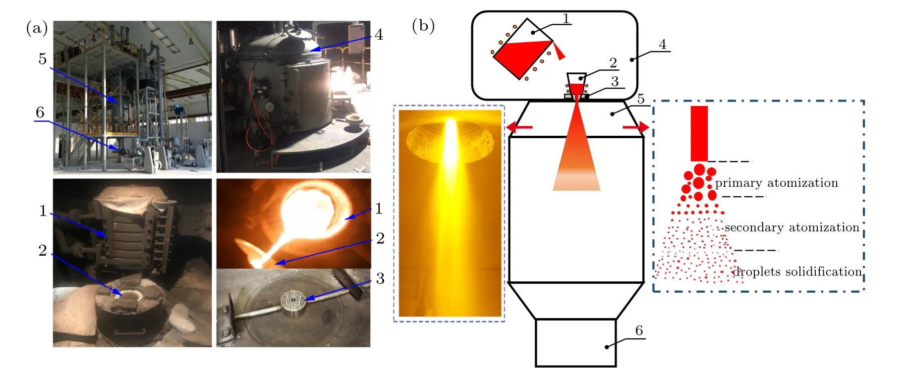
Fig.1. Experimental device and schematic of the VIGA powder preparation method: (1)smelting crucible,(2)insulation crucible,(3)closecoupled nozzle,(4)melting room,(5)atomization tower,(6)powder collector.
2.2. Description of the primary atomization mathematical model
The two-fluid method using the VOF approach, coupled with the large eddy simulation(LES)turbulence model,is employed to simulate the formation and fragmentation of a primary atomization for a typical close-coupled nozzle. In the VOF approach,the volume fraction of liquid(α)is defined in each computational cell. If the cell is filled with liquid,α=1,otherwise α=0.The VOF model is capable of tracking the interface by solving the continuity equation of the volume fraction,which can be given as follows:[18]

In addition, the volume fraction is discretized using the georeconstruct approach. The subscript q represents any one of the two phases.The atomized gas is processed into the primary phase, and its volume fraction is computed using the general constraint shown in Eq.(2). In a two-phase system,for example, if the liquid phase (second phase) of volume fraction is being tracked,parameters such as density in each cell is given in Eq.(3).[18,19]
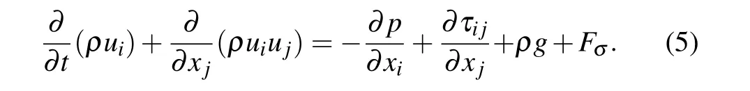
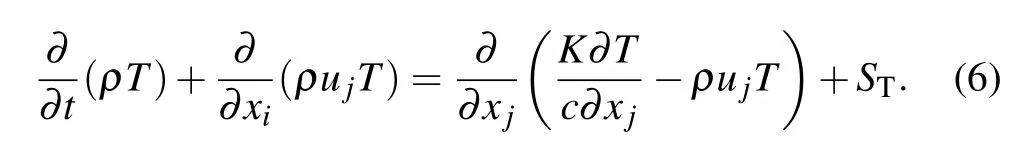
Generally,the Mach number of the close-coupled nozzle gas jet is greater than 0.3,so it is considered to be a compressible gas. Therefore, the gas-liquid flow is governed by the compressible Navier–Stokes(N-S)equations. The mass equation,momentum equation and energy equation are given in the following.[26,27]
Mass equation

Momentum equation
Energy equation
Using the continuum surface force(CSF)method to consider the surface tension effect of liquid flow. The surface tension force is defined as

To improve the accuracy of capturing the primary atomized liquid flow interface, the gradient adaption approach is used, of which the minimum cell size after adaptation is 15µm. Theoretically,it can catch a minimum droplet size of 25µm. Studies by Markus et al. showed that the droplet size after the primary breakup is about 10%–100%of melt nozzle diameter.[28,29]Since the diameter of the melt nozzle is 4 mm,the dynamic mesh refinement is sufficient to meet the accuracy requirements of simulation in the primary atomization process. In addition, the solution process adopts a transient coupled scheme. Density, momentum, and energy are discretized in a first order upwind,and the pressure is discretized in the PRESTO.The 40-core CPU is used to calculate the primary atomization for 336 h,simulating of the physical process is completed for 30 ms, in which the time step is 1×10⁻⁸s,and the final outlet flow rate remains stable at about 0.08 kg/s.It can be considered that the simulation basically converges.
2.3. Description of the secondary atomization mathematical model
The secondary atomization is mainly affected by the surface tension and viscosity, during which aerodynamic force deforms a drop, causing it to become fragment. Therefore,the dimensionless parameter,Weber number We,is defined to describe the secondary atomization
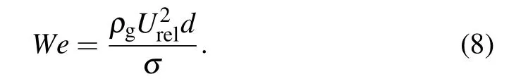
Here, a larger We indicates a higher tendency toward fragmentation.[30]Table 1 and Fig.2 show the different secondary atomization droplet breakup models for metallic droplets with different Weber number ranges, including bag break-up, multi-mode break-up and sheet stripping breakup.[27]
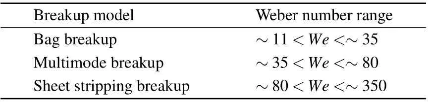
Table 1. Different Weber number corresponding to the breakup model.[31]

Fig.2. Typical modes of droplet breakup.
The bag break-up is analogous to the burst of soap bubbles from a soap film, which is attached to a ring. Though a thin hollow liquid film ruptures to form small fragments,some large droplets are also formed at the edges.[32]
The multi-mode break-up is similar to bag break-up,but a downward liquid ligament is formed in the middle of the liquid film. The liquid film is broken,then the edge and liquid ligaments are disintegrated,resulting in multi-sized fragments.[32]
During sheet stripping,the edge of ellipsoidal droplet directly transforms into a thin liquid film periphery. Then, the liquid film is broken from the periphery to the central part.[27]
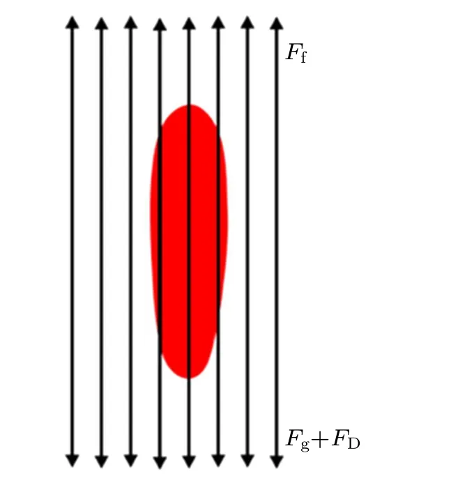
Fig.3. Schematic diagram of a single droplet force.
During the secondary atomization process, the metallic droplets are mainly affected by a dynamic balance of drag force,gravity and buoyancy,as illustrated in Fig.3. Under the action of these forces,the primary atomized droplets undergo ellipsoidal transformation and continue to atomize and break.The specific buoyancy,drag force,and gravity are given in the following.
The buoyant force is
The drag force reads

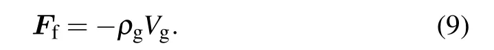
In the secondary atomization, after the spherical droplet undergoes ellipsoidal transformation, various complex deformations and breaks occur. Although the VOF model can realistically simulate the breakup of continuous flow, the further breaking of large number of ellipsoidal transformation droplets cannot continue due to the limitation of computing resources. The discrete phase model and the instability breakup model of the Lagrange method are not suitable for the simulation of continuous liquid flow breakup, whereas they have significant advantages for the simulation of droplet breakup.To realize the prediction of the powder diameter distribution after the secondary atomization,the VOF-Lagrangian method combining the above two methods will be used to realize the simulation of droplet breakup. In this process, by setting the volume equivalent sphere diameter range, maximum radius deviation standard and maximum radius surface orthogonality threshold,the volume fraction droplet breakup by the continuous flow can be converted into droplet particles that can continue to calculate the secondary atomization, as shown in Fig.4. This will effectively avoid the use of a refined grid to capture the volume fraction interface in the droplet breaking process of the secondary atomization, which consumes huge computing resources.
Fig.4. Schematic diagram of the droplet conversion of the VOFLagrangian method.
The radius deviation standard is the value of the standard deviation of the distance between the center of mass of the block and the center of each face grid[34](r1,r2,...,ri),as shown Fig.5(a). The radial surface orthogonality refers to the relationship between the vector connecting center of gravity with face center and the vector of the normal direction of the face grid(see Fig.5(b)). The relative orthogonal range is 0–1,and two vectors overlap for a sphere. Fluent 19.2 generally defines the threshold value of the maximum radius deviation standard and maximum radius surface orthogonality as 0.5, that is, the radius deviation standard and radius surface orthogonality of the droplet meets less than or equal to 0.5,and the shape reaches a spherical shape.[34]Moreover, in the converging stage and initial dispersing stage of the second atomized droplet discussed, the maximum droplet diameter is 1 mm. To reduce the consumption of computing resources before the droplet conversion by the VOF method, the droplet conversion diameter range is set from 0 to 1 mm. In addition,the mesh gradient adaptive method is also used to accurately capture the volume fraction droplet interface, and the smallest cell size after refinement is still 15 µm, catching primary atomized droplets with a minimum size of 25µm.
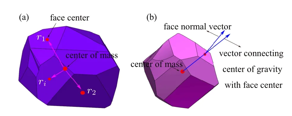
Fig.5. Block sphericity definition standard.
The fragmentation of droplet particles converted by the VOF-Lagrangian method can be explained by the instability break-up model, which mainly includes the TAB model,the KH model and the KH-RT model.[35]In general, the TAB model works better for the bag breakup and multimode breakup(usually for We <80),while the KH model provides strong agreement with experimental data in the sheet stripping breakup (We>80).[35,36]However, Gu et al.[22,36]employed both the models but did not observe any significant difference in mean particle diameter. The KH-RT model built into the Fluent software combines the Kelvin–Helmholtz wave fragments to be considered with the KH model and Rayleigh–Taylor instability,which was developed to simulate higher Weber number atomization. Moreover, it is estimated that the minimum Weber number of droplets after the primary atomization is basically greater than 100, which needs to be described by the KH break-up model. In addition,Thompson et al.[24]demonstrated that the KH-RT model can accurately predict droplets breakup for close-coupled nozzle. Therefore,the KH-RT model is chosen to simulate and predict the powder diameter distribution after secondary atomization.
The KH-RT model combines the effects of the KH model with the Rayleigh–Taylor instabilities due to acceleration of shed droplets ejected into free stream condition.[37]Both the mechanisms model droplet breakup by tracking wave growth on the surface of the droplet,with breakup occurring due to the fastest growing instability based on local conditions. Specifically, in the vicinity of the nozzle, the droplets ejected from the liquid core suddenly accelerate when ejected into the free flow,and RT instability plays a major role at this time.[38]The frequency of the fastest growing wave is computed by[34,39]

where gtis the droplet acceleration in the direction of the droplet travel.The corresponding wave number is given by[34]

Breakup occurs after RT waves have been growing for a time larger than the breakup time,defined as

The radius of the smaller child droplets is dependent upon the RT wave length λRT,

Only when λRTis smaller than the diameter of the parent droplet, the break-up is allowed.[39,40]In addition, the corresponding diameter of the child droplet is obtained from the conservation of mass.
The transformation of metallic droplets into powder is a rapid solidification process, and the heat radiation of the droplets and the internal temperature gradient of the droplets can also be ignored.[27]The cooling of the droplets conforms to the description of the Newtonian cooling model,[26]so the heat transfer equation of the droplets can be expressed as[41,42]

During the simulation process, we adopt the transient coupling solution method,the parameters such as density,momentum and energy adopt the first-order upwind style as the spatial discretization format,and the pressure adopts PRESTO spatial discretization. The powder diameter prediction after the secondary atomization is calculated by 40-core CPU for 477 h,the simulated atomization time is 40 ms,the calculation time step is 8×10⁻⁸s,and the final outlet gas flow is stable at 0.054 kg/s,which achieves simulation convergence.
2.4. Meshing and the boundary conditions setting
In Fig.6,the close-coupled annular slot nozzle is mainly composed of gas inlet, gas chamber, annular slit nozzle and delivery tube. The delivery tube is mainly used to transport the metallic flow, and the key part to form the gas jet is the annular slit nozzle structure. Therefore, in the process of establishing the simulation geometric model,it can be simplified appropriately to remove the nozzle gas inlet and gas chamber.Meanwhile,to reduce the calculation time and cost under the premise of ensuring the accuracy,the actual three-dimensional rotational symmetry model of the nozzle is simplified to a geometric structure of 1/4 rotation period (Fig.7(a)). As the calculation process utilizes the multi-phase flow VOF model to capture the interface of primary atomized droplets, the atomization interval is locally meshed(Φ8.8×15.5 mm)at the same time,the initial number of cell is 1414987 by ICEM software,and the minimum cell size is 0.1 mm(Fig.7(b)). Here,using the VOF model and the VOF-Lagrangian method to simulate the breaking process of the metallic liquid flow and the prediction of the powder diameter,it is necessary to refine the same local area to capture the primary atomized droplets,but the meshes of other areas are relatively coarse. Therefore,the same set of meshes can be used in the simulation process of the two methods. The specific cross-sectional size of the simulation geometry model is shown in Fig.7(c).
As the actual atomization chamber is large,the part near the nozzle(30 mm×128 mm)is considered for simulations.The reasonable selection of boundary conditions during nozzle atomization simulations renders a decisive influence on the accuracy of results. The vertical interface of the revolving body is defined as the periodic boundary. The bottom surface and circumferential surface are considered as spatial positions(Fig.7(a)). During the gas atomization process, the pressure inside the atomization tower is usually stable at −10 kPa and the initial temperature is 300 K, which can be treated as the pressure outlet boundary. Herein,nitrogen was used as the atomizing gas and stainless steel 316L was used as the atomized metal. The physical properties of both materials are shown in Tables 2 and 3. The gas was injected at a constant pressure of 2.5 MPa through the nozzle flow path to atomize the metallic flow. Hence, the annular nozzle gas inlet was defined as the gas pressure inlet boundary, and inlet pressure and temperature values were set to 2.5 MPa and 300 K,respectively. The high-temperature metallic flow in the insulation crucible flows into the atomization chamber through the nozzle delivery tube under the pressure difference between melting chamber and atomizing chamber. Therefore,the metallic liquid inlet is defined as a pressure inlet boundary with 20 kPa pressure and 1700 K temperature.The other surface of the atomization simulation geometry model is the inner wall surface of the actual close-coupled nozzle,which is regarded as the wall boundary.
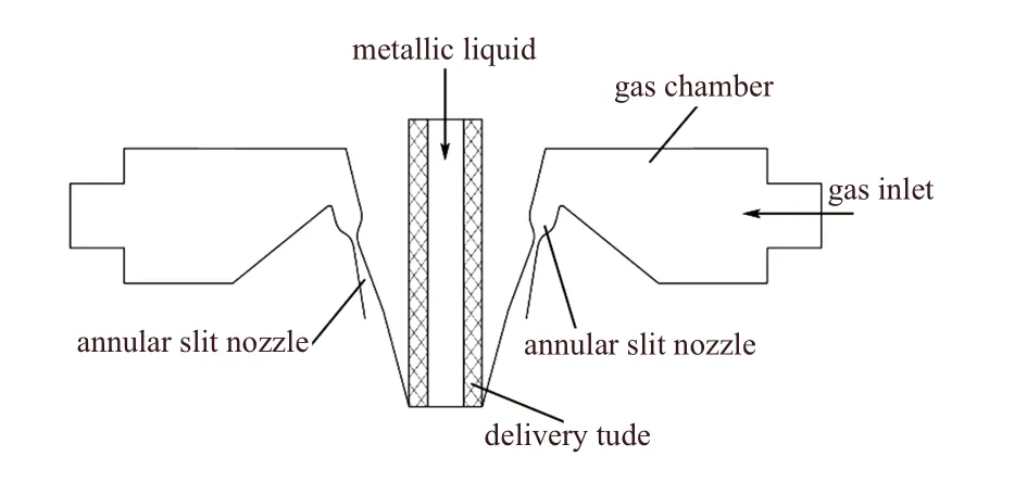
Fig.6. Annular slit nozzle detail of the close-coupled nozzle.
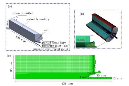
Fig.7. (a)Nozzle simulation geometry model and boundary condition distribution. (b)Nozzle simulation mesh model. (c)Nozzle simulation geometry model section size distribution.

Table 2. The 316L alloy melt molten parameters.[19,25]

Table 3. Nitrogen physical parameters.
Further, the annular gas jet merges at the bottom of the recirculation zone and flows in a vertical downward direction.In the initial dispersion stage of the secondary atomization of the metallic liquid flow passing through the gas recirculation zone,the droplets mainly exist in long elliptical shapes,at this time the droplets are mainly subjected to the vertically downward combined gas jet. Due to the limitation of computing resources, it is difficult to directly simulate the secondary atomization of droplets for close-coupled nozzle using the VOF model. To further study the sub-droplet shape of the ellipsoidal droplets after breaking,the area around a single droplet was randomly taken as a sub-model in the initial dispersion stage, carrying out the secondary atomization simulation of the ellipsoidal droplets.
To simplify the simulation, the ellipsoidal droplets are simplified to rectangular long droplets, with corresponding droplet size, gas velocity and other parameters shown in Table 4 (parameters are obtained from the simulation results of the initial dispersion stage). In Fig.8, the two-dimensional model of a rectangular area of 6×1.2 mm near the droplet is selected to simulate the breaking process of the long droplet.Using ICEM software for mesh division,the initial number of cells is 1146244, and the minimum cell size is 2 µm. Furthermore, the VOF model is coupled with the LES model to simulate the breaking process of long droplets. The top of the droplet is defined as the velocity inlet boundary, and the bottom is defined as the pressure outlet boundary. Due to the small area near the droplet selected in the fluid domain, the boundary position on both sides of the droplet can be considered as no velocity gradient, and equivalently treated as the wall boundary. In the simulation process, density and momentum are set as a first-order upwind style, and the pressure is discretized using PRESTO, and the volume fraction is discretized in a geo-reconstruct method. The 40-core CPU was used to calculate the single-droplet atomization for 40 h, simulating atomization process is 18.9 µs, the time step is 6×10⁻⁹s, and the final outlet gas flow is stable at−9.278 kg/s,which can be considered as the simulation convergence.

Table 4. Simulation parameters of single droplet breaking.
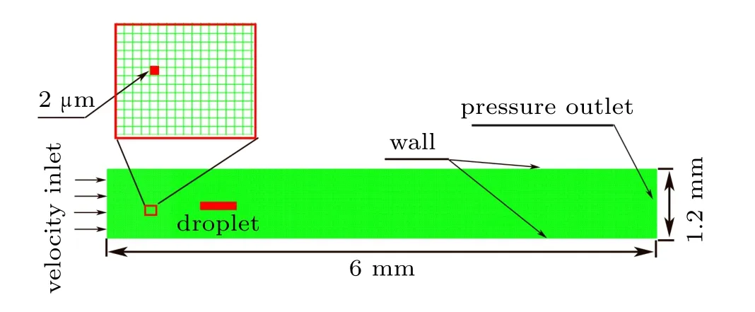
Fig.8. Establishment of simulation model for droplet breakup.
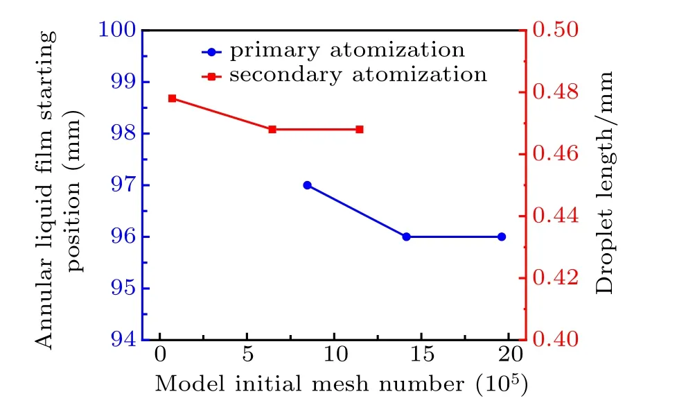
Fig.9. Position distribution of liquid film and length distribution of droplet under different model mesh numbers.
Figure 9 shows the starting position of the liquid film and the droplet length distribution under different mesh numbers of the close-coupled nozzle model and the sub-model of the secondary atomization simulation. The number of meshes of the close-coupled nozzle model are 846426, 1414987, and 1960980 respectively. When the transient simulation time is 27 ms, the axial coordinates of the starting position of the annular liquid film for the primary atomization are 97 mm,96 mm and 96 mm, respectively. When the number of meshes for the close-coupled nozzle increases from 1414987 to 1960980, the starting position of the annular liquid film is stable at 96mm. It can be considered that the number of meshes used in the primary atomization simulation(1414987)is independent. In addition, the secondary atomization submodel is divided into different mesh numbers, which are 71281, 645841, and 1146244, respectively. When the transient simulation time is 7.6µs,the lengths of the long droplet are 0.478 mm,0.468 mm,and 0.468 mm,respectively. In general,as the number of mesh of the secondary atomization submodel is reduced from 1146244 to 645841, and the length of the long droplet at the same time is stable at 0.468 mm,so the number of mesh of 1146244 adopted in the secondary atomization simulation is also independent.
3. Results and discussion
3.1. Close-coupled nozzle gas-liquid flow velocity field analysis
The atomization of close-coupled nozzles is a complicated process of gas-liquid two-phase flow interaction. When the metallic liquid flows through different positions,it has different effects on the mixture velocity flow field of the nozzle.Figure 10(a) shows the mixture velocity flow field distribution when the metallic liquid flows out from the bottom of the delivery tube. The compressible gas enters the furnace through the nozzle airflow path,where one-dimensional isentropic flow with increased speed and reduced pressure occurs.This results in a pressure difference between the nozzle exit and ambient within the atomizing tower, forming chain-like Prandtl–Meyer clusters at the nozzle exit.[43–45]The existence of gas shock wave structure can accelerate the attenuation of gas,which is not conducive to the efficient preparation of fine powder.[17,25]Further,limited by the nozzle structure,the gas jet gathers at a certain angle to the center of the nozzle bottom. During this process, the flow path of airflow gradually deflects and forms a recirculation structure[46]above the intersection of the airflow. When the gas jets meet, the major portion of obliquely injected airflow deflects vertically downwards. Moreover, a portion of airflow moves vertically upward and, after contacting the bottom of the delivery tube, it continues to extend in the radial direction until contacting the oblique supersonic jet boundary. With the influence of strong turbulent flow energy of the gas jet,the air streams flowing in recirculation zone are combined and return to the initial point of recirculation zone to complete the recirculation cycle. In addition,the location of the gas recirculation zone also has an effect on the gas flow in the delivery tube.If the position of the recirculation zone is too high, it is easy to cause the air flow in the delivery tube to flow upward,which hinders the smooth flow of the metallic liquid,otherwise it is easy for the gas flow in the delivery tube to flow downward, accelerating the flow of the metallic liquid. According to the flow trajectory of the gas recirculation zone,the gas flow entering the gas recirculation zone is smaller than the radial flow out of the recirculation zone,which is the basic condition to ensure the suction speed of the downward flowing air in the delivery tube.[46]This will promote the flow of metallic liquid and prevent the solidification in the delivery tube or at the bottom.

Fig.10. Mixture velocity distribution of gas-liquid flow at different moments. (a)Mixture velocity distribution when the metallic liquid flows out from the bottom of the delivery tube. (b)Mixture velocity distribution when the metallic liquid flows through the recirculation zone. (c)The mixture velocity distribution of axis position at different moments.
Further, when the metallic liquid flows through the gas recirculation zone, the structure of the obvious gas recirculation zone disappears due to the interaction between the flow of metallic liquid and gas,as shown in Fig.10(b). During the downward flow of metallic liquid,the mixture velocity intensity in the middle of the gas flow is lowered. At the same time,the uneven airflow shedding structure appears at the edges of the middle airflow, and high-speed airflow region is slightly deflected in the radial direction. When the metallic liquid flows out from the bottom of the delivery tube, the mixture velocity distribution at the axis position in the recirculation zone is distributed in an arch shape,but once the metallic liquid flow passes through the gas recirculation zone,the arched peak of the mixture velocity distribution at the axis position disappears,as shown in Fig.10(c). In addition,under the load of the metallic flow,the mixture velocity in the axial position below the gas recirculation zone also significantly decreases.In general,during the atomization of the metallic flow,the gas recirculation zone changes significantly. The influence of the gas recirculation zone is further analyzed, through the atomization of the metallic flow.
3.2. Close-coupled nozzle primary atomization process analysis
The primary atomization process of the close-coupled nozzle initiates when the metallic liquid, flowing out of the delivery tube, contacts with the gas recirculation zone. Once the metallic liquid flows to the top of recirculation zone, the downward flow is gradually decelerated due to the resistance of gas flow in recirculation zone. Hence, the metallic liquid starts to flow in radial direction. At this time,the metallic liquid flow is mainly affected by the pressure(Fp)(including gas pressure at the top and hydraulic pressure),gas drag force(FD)in delivery tube,gravity(Fg)and the buoyancy(Ff)of the gas recirculation zone. There is a downward gas suction speed in the delivery tube,forming a downward gas drag force,which is the prerequisite for the metallic liquid pass to through the delivery tube smoothly.If Fp+Fg+FD>Ff,the general metallic liquid flow can be smoothly atomized and broken through the delivery tube.However,if Fp+Fg+FD<Ff,the metallic liquid flow gradually decelerates,and it will be easy to solidify the metallic liquid in the delivery tube and block the channel, which will not be conducive to the atomization process.The Fp+Fg+FD>Ffis the basic condition for the closecoupled nozzle to smoothly atomize the metallic flow. Among these factors,the pressure Fpis directly controlled by the upper chamber where the insulation crucible is located,however the buoyancy and drag force are mainly affected by the gas recirculation zone. Therefore, the nozzle atomizing gas pressure, the spray angle and the delivery tube extension length,which have an influence on the gas recirculation zone,are the key factors to control the smooth atomization of the nozzle.The gas recirculation zone that forms gas buoyancy gradually shrinks to a fixed size under the action of pressure,drag force and gravity, forming a stable annular umbrella-like film (see Fig.11). Zeoli et al.[43]studied a similar structure of a miniature fountain. With continued atomization, the thickness of loop-shaped umbrella-like liquid film is reduced. When the liquid film is close to the boundary of supersonic jet,pulsating shearing action of turbulent flow and surface wave of liquid film are simultaneously promoted. However, before reaching the critical thickness,the liquid film does not break and flows are downward along the sonic jet boundary.
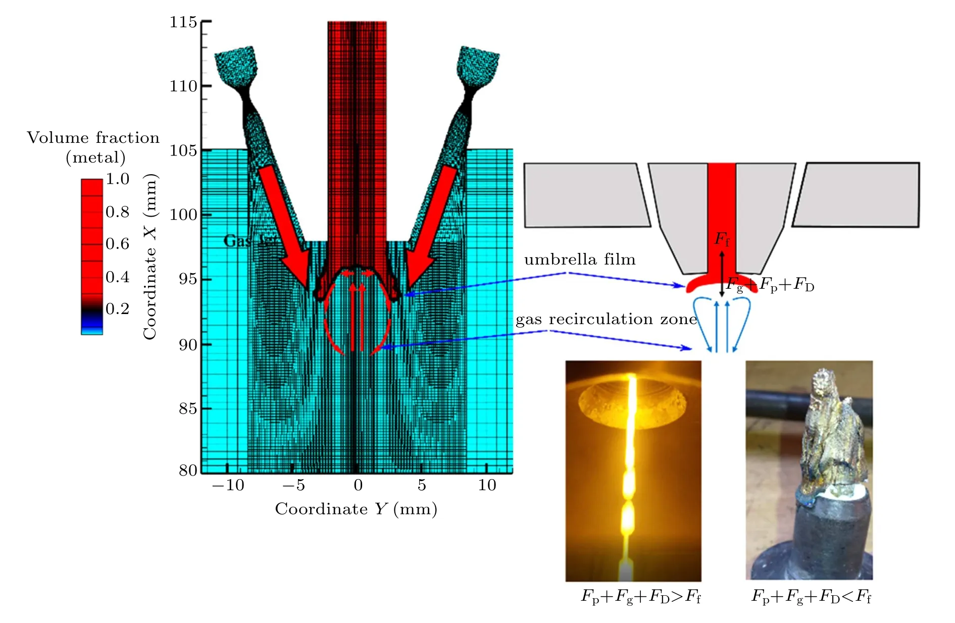
Fig.11. The umbrella-like liquid membrane structure during primary atomization.
In Fig.12(a), when the liquid film thickness is reduced to a critical value, it exhibits an asymmetrical fold deformation under the action of pneumatic turbulent disturbance at the boundary of sonic jet. The tip edge of the annular liquid film exhibits various wrinkle depths at different locations. Some of the tip thicknesses reach the critical value,forming a small number of broken droplets. As indicated in Fig.12(b), the broken liquid film continues to move downward,however,the movement is accompanied by curling and tearing of the liquid film. The wrinkled tip deforms to form a serrated liquid film tip morphology. The thickness and surface wave of the serrated liquid film tip reach a critical value and form primary atomized droplets. Figure 12(c)shows that the portion of serrated liquid film,which has not been broken and continues to flow downward, forms a ligament structure with a high peak between the segments. Owing to airflow shearing and surface tension,the ligament liquid wave peels off from the peak position of surface wave and forms spherical droplets,constituting the primary atomization process of the close-coupled nozzle.The primary atomization process mainly includes the formation of surface liquid film, appearance of serrated ligaments,and shredding of ligaments.

Fig.12. The primary atomization process of metallic liquid flow(in this study,the metallic liquid iso-surface with a volume fraction of 0.25 is defined as the gas-liquid boundary): (a)wrinkling of liquid film,(b)formation of serrated ligaments,(c)formation of ligaments and shedding.
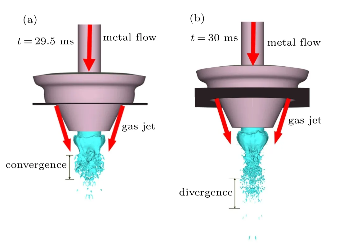
Fig.13. The initial secondary atomization process of metallic liquid flow: (a) convergence segment distribution, (b) initial divergence segment distribution.
¨Unal et al.[14]used high-speed cameras to photograph the process of preparing aluminum powder with a close-coupled nozzle of the VIGA process at low metallic flow rate. The process shows the annular umbrella-like film structure of the primary atomization, as well as the appearance of wrinkles and serrated ligaments at the edge of the annular liquid membrane. Although there are differences in material composition between the aluminum alloy and the studied 316L stainless steel alloy, the flow state of the liquid atomization process should be basically the same. The shape of the annular liquid film formed by the aluminum atomization process taken by ¨Unal is basically similar to that of the primary atomization process of this simulation. This also proves the correctness of the primary atomization simulation and the feasibility of the theory of annular liquid film formation to a certain extent.
In Fig.13(a), during the initial secondary atomization, a large amount of various droplets is formed by separating from the main liquid film, and a mixture of surface-like droplets,band-like droplets and fine droplets is formed by combining the primary droplets. Figure 13(b)shows that the flow direction of droplets gradually becomes parallel to the airflow due to the airflow drag, dispersing the droplet groups into location close to the boundary of the gas jet(see Fig.10(b)), and the shear effect of the gas stream is also increased. Furthermore, the liquid film is broken and torn into droplets. Then,the droplets start to transform into ellipsoidal droplets and the liquid film thickness is gradually reduced. The liquid film becomes instability after reducing to a certain thickness. The edge of liquid film is broken under the action of gas jet turbulent flow, resulting in the formation of fine droplets and constituting the secondary atomization process. Obviously, the secondary atomization process can be divided into two stages:droplet convergence and droplet dispersion, as shown by our experimental verification (Fig.14), which is consistent with the aforementioned simulation result. In summary, the process occurs due to the interaction between the inner boundary of gas jet and metallic flow (see Fig.10(b)). Moreover,the convergence stage only occurs in a small area below the nozzle,however,the divergence stage occurs in almost the entire area of the atomization furnace below the nozzle, which includes the divergence,deformation,breaking and solidification of most of the droplets of the secondary atomization.
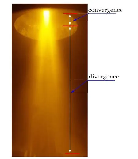
Fig.14. Image of the atomization process of 316L metal powder by the close-coupled nozzle.
Furthermore, the concepts of equivalent volume diameter(dV)and equivalent surface diameter(dS)are introduced to assess the diameter distribution during both stages,

In both the stages of secondary atomization, the delaunay triangle method of MATLAB software was used to calculate the equivalent volume and equivalent surface of the atomized droplet to realize the droplet diameter calculation.Figure 15(a) shows that the equivalent volume diameter during the convergence stage(count the number of 152 droplets)ranges from 25 to 425 µm, where the mass medium diameter (MMD d50) is 158 µm. However, the equivalent surface diameter ranges from 30 to 650 µm, where d50=180 µm.Based on the average of both droplet sizes (d50), the equivalent surface diameter is greater than the equivalent volume diameter of 22µm. Figure 15(b)shows that the initial dispersion stage(count the number of 300 droplets)equivalent volume diameter mainly distributes in the range of 40 to 680µm,where d50= 150 µm. However, the equivalent surface diameter is mainly distributed in the range of 80 to 1000 µm,where d50=200 µm. Based on the average of both droplet sizes(d50),the equivalent surface diameter is greater than the equivalent volume diameter of 50 µm. In theory, the volume equivalent diameter of an ideal spherical droplet is equal to the surface equivalent diameter. The sphere is a 3D structure with the smallest surface area under the same volume. Therefore,once the droplets are non-spherical, it will lead to the phenomenon that the equivalent surface diameter is larger than the equivalent volume diameter. During the transition from the convergence stage to the initial dispersion stage,the difference between the equivalent surface diameter and equivalent volume diameter gradually increases,which may be the result of non-spherical deformation of the droplet during this process.
Further the morphology of droplets in the two stages is assessed by its sphericity,which can be defined as
“现在在城市里坐车真的太方便了,我们农村实在没得比。”我在后面插了一句。表哥转过头来,瞪着我说:“你以为呢?”见表哥不高兴,我吐了下舌头,就不敢再说什么。
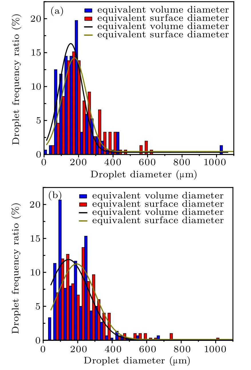
Fig.15. Comparison of different diameter evaluation standards: (a)convergence stage,(b)initial dispersion stage.
In Fig.16, the sphericity of the droplet in the initial dispersion stage is in the range of 0.25–0.95,while the sphericity of the droplet convergence stage is within the range of 0.37–0.9.Furthermore,in the initial dispersion stage,the proportion of droplets in the range of 0.25–0.62 is greater than that in the convergence stage. However, when the droplet sphericity is in the range of 0.62–0.85, the proportion of droplets in the convergence stage is greater than that in the initial dispersion stage.If the sphericity of the droplet is closer to 1,it will mean that the morphology of the droplet is closer to the ideal sphere.Once the droplet undergoes an ellipsoidal transformation,the sphericity gradually approaches 0. Therefore, it can be further considered that from the convergence stage to the initial dispersion stage, the droplets have undergone an ellipsoidal transformation.
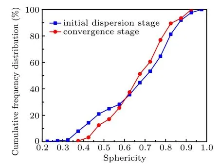
Fig.16. Cumulative distribution of droplet sphericity.
3.3. Close-coupled nozzle secondary atomization process analysis
In Fig.17, the vertical downward flow is separated by long droplets,forming a gas recirculation zone at the bottom of the droplets.In addition,the gas flow accelerates from 300 m/s to 500 m/s on the side of the droplet. During droplet atomization, the droplet is mainly affected by the drag force (FD),gravity (Fg) and gas buoyancy (Ff) of the bottom gas recirculation zone. When a single droplet is atomized, the broken child droplets gradually separate from the mother droplet, so that the volume of the mother droplet decreases, which will cause the buoyancy of the droplet during the atomization process to gradually decrease(see Eq.(9)). However,in the early stage of long droplet deformation and breaking,neglecting the change of the maximum cross-sectional area of the droplet,increasing in gas velocity on the side of the droplet causes an increase in drag force(see Eq.(10)).

Fig.17. Velocity cloud diagram of single droplet atomization.
In Fig.18, under the squeeze of the drag force and gas buoyancy,the top of the droplet gradually flows along the side,forming an annular fountain-like liquid film. The edge of the fountain-like liquid film is torn and broken under the action of drag force.As time goes by,the height of the fountain-like liquid film gradually decreases, and finally a thin annular liquid film structure is formed, which may tear and break under the action of aerodynamic force. Moreover, this is very similar to the ring-shaped liquid film structure formed by the sheetthinning of droplets taken by Guildenbecher with high-speed photography.[47]Furthermore, the partial zoomed in display shows the fine droplets (diameter basically less than 30 µm)formed after the long droplets are atomized, which are basically small near-spherical droplets.

Fig.18. Distribution of single droplet breaking volume fraction at different moments(all the parts with a droplet volume fraction greater than 1%are described in the same color to show as much as possible the details of the droplet interface after breaking).
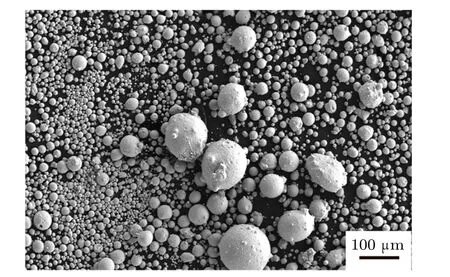
Fig.19. SEM image of the metallic powder actually prepared.
Figure 19 shows the actual metallic powder prepared by the close-coupled nozzle,and most of the fine powder(diameter less than 30 µm in diameter) have a very high degree of sphericity. However,coarse powder mostly exists in the form of satellite powder with poor sphericity. Although there are some agglomerations of fine powder, this may be caused by artificial spreading of the powder when preparing the SEM sample. Therefore, this further proves the credibility of the conclusion discussed above that long liquid droplets basically form fine spherical powder after atomization.
Further,the VOF-Lagrangian method was used to predict the diameter of the powder after the secondary atomization of the close-coupled annular slit nozzle. Figure 20 show the convergence and dispersion stages in the secondary atomization process. Though this method cannot reflect the true droplet shape after atomization,it can reflect the secondary processes from convergence to dispersion stage through the particle diameter distribution.
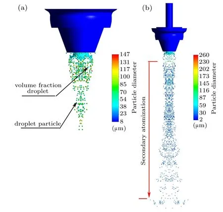
Fig.20. Particle diameter distribution during secondary atomization:(a)convergence stage,(b)dispersion stages.
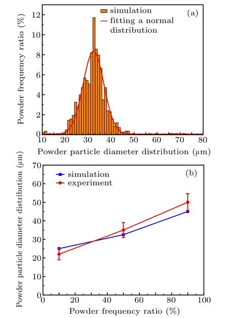
Fig.21. The diameter distributions of secondary atomized powder: (a)simulated powder particle diameter distribution,(b)comparison of simulated and experimental results.
Figure 21(a)shows the simulated particle diameter distribution after secondary atomization, indicating that the diameter of the powder ranges from 20 to 50 µm and the MMD is 32.5 µm (d50). Compared with the surface equivalent diameter of 200µm and volume equivalent diameter of 150µm during initial dispersion stage,the particle size is significantly reduced due to the breaking of ellipsoidal droplets. The theoretically calculated d50,d90and d10values are 32.5µm,45µm and 25 µm, whereas the corresponding experimentally measured values are 35±4µm,50±4.6µm and 22±3µm,respectively. Figure 21(b)shows that experimental and simulated results show excellent consistency,demonstrating the reliability of adopted theoretical model.
3.4. Close-coupled nozzle typical powder morphology formation analysis

Fig.22. The SEM image of typical powder morphology: (a)spherical powder,(b)torn-surface powder,(c)incompletely fused powder,and(d)satellite powder.
Figure 23 shows the formation of four different types of droplets, including bonded droplet, spherical droplet, ellipsoidal droplet and sheet droplet during the primary atomization stage. Moreover, four different types of droplets are formed during the initial secondary atomization stage, including spherical droplet, curved droplet, ellipsoidal droplet and bonded droplet. In general, there are mainly five types of droplets formed from the primary atomization to the secondary atomization droplet deformation stage,mainly including spherical droplet,ellipsoidal droplet,sheet droplet,curved droplet and bonded droplet.

Fig.23. Typical single droplet shape at different stages(the color change of the droplet in the figure only shows the change in the size of the droplet in the z-axis direction and has no other physical meaning): (a)primary atomization stage,(b)initial secondary atomization stage.
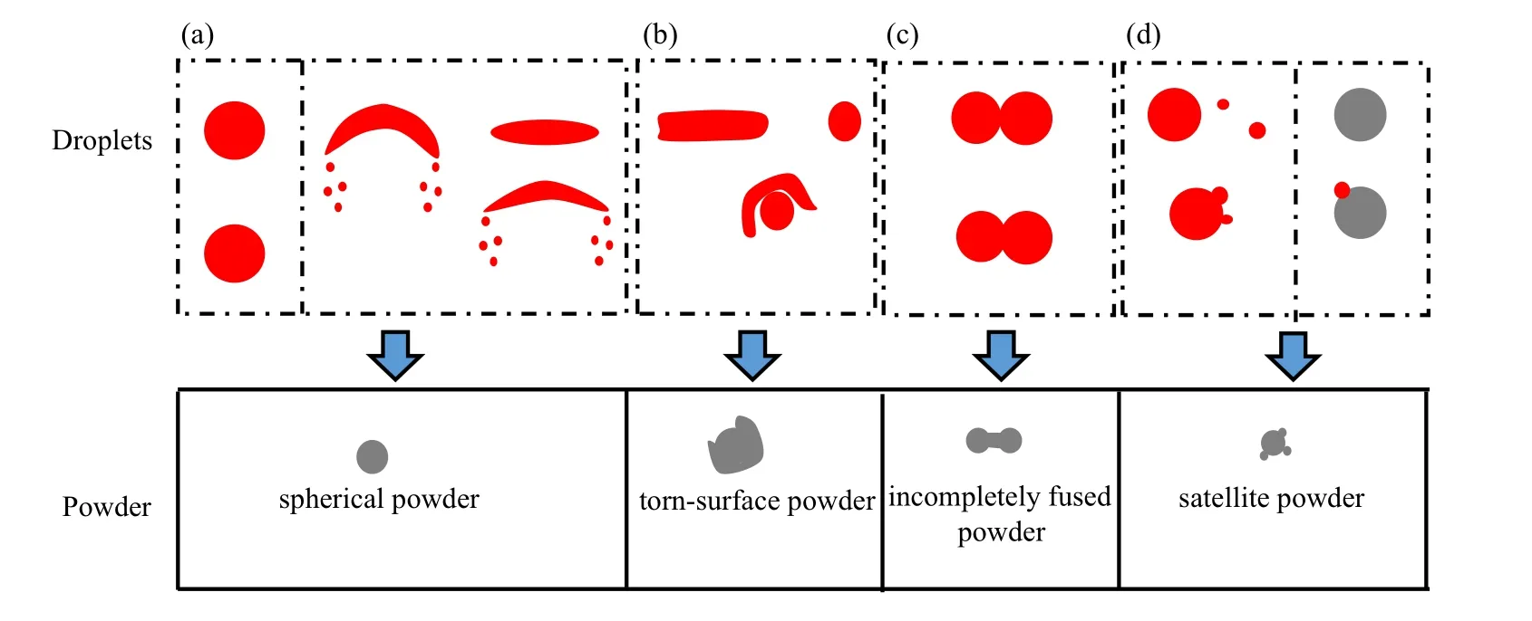
Fig.24. The relationship between the morphology of the prepared powder and the simulated droplet shape.
Metal powder is the product formed by the deformation,breaking, shrinking and solidification of droplets in different stages of atomization. Figure 24 shows the relationship between typical droplets and metallic powders with different morphologies. There are two main paths for the formation of spherical metal powder (see Fig.24(a)). The first is the direct solidification of spherical droplets in the primary atomization stage or the secondary atomization stage to form spherical metal powder.Secondly,the curved droplets or ellipsoidal droplets with higher superheat will undergo further deformation and breakage under the action of aerodynamic force to form fine spherical droplets, which has been proven in Subsection 3.3. In addition, the torn-surface powder is mainly formed because the sheet droplets formed in the primary atomization stage collide with the spherical powder,causing the sheet droplets to wrap the spherical powder (see Fig.24(b)).Moreover, when the superheat of the bonded droplets in the primary atomization stage or the initial secondary atomization stage is low, aerodynamics cannot separate the bonded droplets again, so the droplets will solidify and form incompletely fused powder(see Fig.24(c)). Finally,during the further fragmentation of the elliptical droplets or curved droplets,the formed fine droplets collide with larger size droplets or these fine droplets collide with solidified powder to form satellite powder(see Fig.24(d)).
In general, the solidification of spherical droplets or the further fragmentation of ellipsoidal droplets and curved droplets is beneficial to the formation of spherical powder. However, the collision between droplets and powder or droplets and droplets is not conducive to the formation of spherical powder. For example,the collision of sheet droplets and fine spherical powder will easily form torn-surface powder,and the collision of fine droplets and spherical powder will easily form satellite powder. The collision between droplets and droplets or between droplets and powder is mainly the result of nozzle gas jet acting on the powder or droplets. Therefore, the key to preparing spherical powder is to reasonably control the gas jet,reducing the collision between droplets and powder.
4. Conclusion and perspectives
The simulation of gas-liquid two-phase flow atomization at a three-dimensional scale of a close-coupled annular nozzle is conducted by the VOF approach,which can show the metallic flow breakage and the droplet deformation breakup process.The simulation results show that the gas recirculation zone plays a decisive role in the formation of the primary atomized annular umbrella-shaped liquid film. In addition, the metallic liquid flow in the delivery tube meets Fp+Fg+FD>Ffis the basic condition for the nozzle to be able to atomize smoothly. In addition,the primary atomization process of the close-coupled nozzle mainly includes the formation of surface liquid film,appearance of serrated ligaments,and shredding of ligaments.The secondary atomization mainly includes droplet converging stage and droplet dispersion stage,and the dispersion stage of the droplets basically includes the entire area below the nozzle.
Due to the limitation of computing resources, it is difficult for the VOF method to continue the ellipsoidal droplet fragment process simulation and prediction of powder diameter distribution for close-coupled nozzle after secondary atomization. However, a single ellipsoidal droplet is selected to establish a sub-model, simulating the droplet breaking can be realized by coupling the VOF model and the LES model,which realize the prediction of the morphology of the subdroplets formed after the ellipsoidal droplets are broken. As a result, the simplified long droplet of the elliptical droplet mainly forms fine near-spherical droplets less than 30µm after breaking, which is consistent with the morphology of the powder actually prepared. In addition, the VOF-Lagrangian method and the KH-RT model are used to predict the powder diameter distribution after secondary atomization. Finally,the particle diameter prediction of the secondary atomization simulation is in good agreement with the experimental powder size distribution.
During the atomization process of the close-coupled nozzle, four morphologies powders are mainly formed, namely spherical powder, torn-surface powder, incompletely fused powder and satellite powder. Moreover, five typical droplet shapes are also formed,including spherical droplet,ellipsoidal droplet, sheet droplet, curved droplet and bonded droplet.Spherical droplets,curved droplets and ellipsoidal droplet are more likely to form spherical powder, while the collision of sheet droplets and fine spherical powder or the collision of fine droplets and spherical powder are not conducive to the formation of spherical powder. Therefore,in order to prepare spherical powder, it is important to reasonably control the gas jet of the close-coupled nozzle,reducing the collision of droplets during the atomization process.
Appendix A
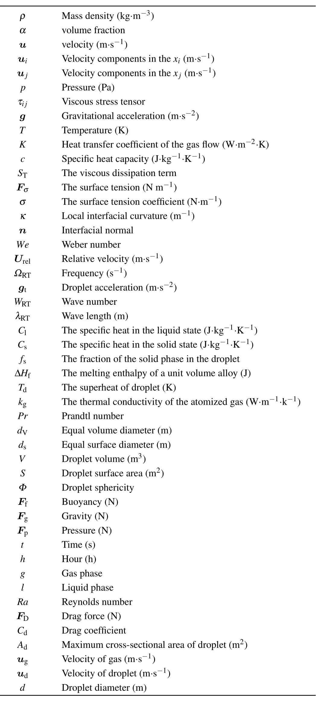
Nomenclature
猜你喜欢
作文周刊·小学一年级版(2022年24期)2022-06-18
Chinese Physics B(2021年11期)2021-11-23
作文·小学低年级(2021年4期)2021-11-02
太空探索(2021年2期)2021-02-27
Chinese Physics B(2021年1期)2021-01-21
少儿科技(2021年3期)2021-01-20
教学考试(高考语文)(2017年5期)2017-12-13
中学数学杂志(初中版)(2017年4期)2017-08-28
民生周刊(2012年8期)2012-12-23

- Chinese Physics B的其它文章
- Novel traveling wave solutions and stability analysis of perturbed Kaup–Newell Schr¨odinger dynamical model and its applications∗
- A local refinement purely meshless scheme for time fractional nonlinear Schr¨odinger equation in irregular geometry region∗
- Coherent-driving-assisted quantum speedup in Markovian channels∗
- Quantifying entanglement in terms of an operational way∗
- Tunable ponderomotive squeezing in an optomechanical system with two coupled resonators∗
- State transfer on two-fold Cayley trees via quantum walks∗