
Line-scanning confocal microscopic imaging based on virtual structured modulation
2021-04-20 06:06:02ZHAOJiawangZHANGYunhaiWANGFaminMIAOXinSHIXin
中国光学
2021年2期
ZHAO Jia-wang,ZHANG Yun-hai ,WANG Fa-min,MIAO Xin,SHI Xin
(1.School of Biomedical Engineering, University of Science and Technology of China, Hefei 230026, China;2.Jiangsu Key Lab of Medical Optics, Suzhou Institute of Biomedical Engineering and Technology,Chinese Academy of Sciences, Suzhou 215163, China;3.The Second Affiliated Hospital of Soochow University, Suzhou 215000, China)
Abstract:Resolution in a confocal microscope is limited by the diffraction limit.Structured modulation has been proven to be able to achieve super-resolution in confocal microscopy,however,its limited speed in image acquisition limits its applicability in practical applications.In order to improve its imaging speed,we introduce a method that can achieve rapid super-resolution confocal microscopy by combining line-scanning and structured detection.A cylindrical lens is used to focus the light into a line,and a digital mask with a sinusoidal function is used to modulate the descanned image in the light detection arm.Unlike the virtual structured method,there is no need for a subsequent frequency shift process.In order to improve the isotropic resolution of the system,a scanning angle of 0°and 90°is achieved by rotating the sample.Simulation and experiment results indicate that the spectrum width of coherent transfer function expands and the resolution is 1.4 times as large as that of a conventional confocal microscope.This method increases the system’s imaging acquisition speed 104-fold when compared with a confocal structured modulation microscope that uses spotscanning.
Key words:line-scanning confocal;super-resolution;virtual structured modulation
1 Introduction
Due to the diffraction effect of light wave,the resolution of a traditional optical microscope is limited[1-2].Laser-Scanning Confocal Microscopy(LSCM)has a higher resolution than wide-field microscopy because it uses a tightly focused excitation beam and pinhole detection to suppress the defocusing background light[3-4].However,due to the limitation of pinhole size,the resolution of a confocal microscope with smaller pinhole is achieved at the price of SNR reduction.To achieve their balance,the pinhole size is generally large,resulting in a lateral resolution lower than the ideal result but still within the diffraction limit[5-6].In the past two decades,many super-resolution optical microscopy methods such as Stimulated Emission Depletion(STED)microscopy[7]and Structured Illumination Microscopy(SIM)[8]have been applied.These methods follow two main principles,namely,decreasing the size of Point Spread Function(PSF)and increasing the bandwidth of Optical Transfer Function(OTF)[9].In addition,Stochastic Optical Reconstruction Microscopy(STORM)[10]and Photo-Activated Localization Microscopy(PALM)[11]can achieve super-resolution by using an optically switched fluorescent probe to locate a single molecule.These methods have made breakthroughs in fluorescencelabeled imaging resolution.However,each of them also has some limitations.PALM and STORM have long been limited by their imaging speed.In the STED microscopy,the excitation and emission spectra are required to match the given excitation wavelength and depletion wavelength.SIM can only image optical thin samples[12].
The structural detection microscope is derived from the principle of structured illumination and its resolution enhancement concept is similar to Moire fringe.By acquiring images through optical masks at different scanning locations,the OTF bandwidth is doubled compared with a traditional microscope[13].However,wide-field space structure illumination is not suitable for a scanning microscope,due to the need for a patterned mask(such as a grating)at the illumination end.With the proposing of Scanning Patterned Illumination(SPIN)microscopy and Scanning Patterned Detection(SPADE)microscopy,super-resolution laser scanning microscope has been realized.These methods have achieved the same effect as SIM in the point scanning system by using the time and space modulation[14].SPADE,also known as Virtual Structure Detection(VSD),has been proven correct.However,since the spot image of each scanning point is needed,the imaging speed in VSD is severely limited[15].
To overcome the above shortcomings,virtual structured modulation has been applied to largeaperture confocal microscope by means of Linescanning confocal microscopy with Virtually Structured Modulation(LVSM)microscopy[16],thus improving the speed and resolution of confocal microscopic imaging.Its difference from VSD is that no subsequent frequency shift is required.At the same time,thick samples can be imaged due to the unique slicing ability of confocal microscope.Different from most of the other super-resolution imaging methods,this method can image non-fluorescent samples with high resolution and fast imaging speed.
2 Principle of line-scanning confocal virtual structure modulation
The reflective confocal coherent imaging system is shown in Fig.1.

Fig.1 Schematic of reflective confocal microscope system图1 反射式共聚焦系统示意图
Suppose the illumination intensity and the system amplification factor are 1.In the case of unscanning,the phase factor is ignored after the interaction between the illumination light field and the sample.Then the amplitude distribution on the sample surface will be:

wherehil(x,y)is the two-dimensional amplitude PSF of the illumination path,sis the amplitude distribution of the sample,and(x1,y1)is the location of the sample.After passing through the detection light path,the contribution of the light field amplitude distributionA1(x,y,x1,y1)obtained after the interaction between the sample and the illumination light field to the amplitude of a point(x2,y2)on the image plane can be expressed as:

wherehde(x,y)is the two-dimensional amplitude PSF of the detection path,andA2(x,y,x1,y1,x2,y2)is the contribution of the amplitude distribution obtained after the interaction between the sample point(x1,y1)and the illumination light field to the point(x2,y2)on the image plane.The superposition of the contributions of all the sample points to the amplitude at that point is just the amplitude detected on the image plane.The amplitude distribution on the whole image plane is:
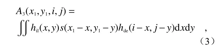
whereA3(x1,y1,i,j)is the amplitude distribution on the image plane.If the detection function isD(i,j),then:
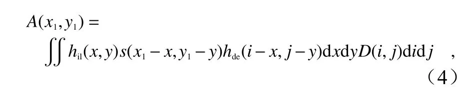
whereA(x1,y1)is the amplitude image finally detected by the detector.Bothhil(x,y)andhde(x,y)are even functions.The definition of convolution is applied to obtain:
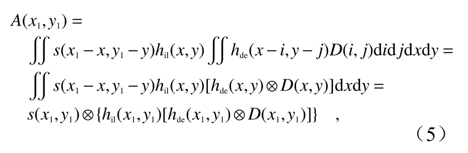
It can be seen from Eq.(5)that the final amplitude image is the superposition of the amplitudes at different positions of the sample.This is a coherent imaging process.The imaging characteristics of the system depend on the amplitude PSF:

Then the Coherent Transfer Function(CTF)of the system can be expressed as the Fourier transform of APSF:

whereHil(fx1,fy1)andHde(fx1,fy1)are the CTFs at the illumination end and detection end respectively,⊗represents two-dimensional convolution,and F is the symbol of Fourier transform.According to Eq.(6),the Intensity Point Spread Function(IPSF)of the system can be expressed as[17]:

Since the imaging performance of the system is ultimately limited by lens,lighting mode and detection function,the forms of system amplitude PSF under different conditions will be discussed separately.
The scanning mode in which the lighting mode is point lighting andD(x1,y1)is a virtual pinhole is point-scanning mode.The amplitude PSFs for illumination path and detection path can be derived from the Fourier transform of the lens aperture.The effective detection PSF is the convolution of the detection PSF and the aperture functionD(x1,y1).
The scanning mode in which the lighting mode is line lighting andD(x1,y1)is a virtual slit is linescanning mode.Compared with point scanning,the amplitude PSF of the detection path remains unchanged.Since a cylindrical lens is introduced to focus the spot on the illumination path,the amplitude PSF of the illumination path will change into Gaussian distribution in one direction and constant distribution in the other direction.Suppose the scanning direction is along theXaxis,that is,the illumination PSF is a constant distribution in theYaxis direction.Then under the paraxial approximation,the amplitude PSF of the illumination path can be written into[18]:

whereΦ=2πNA/λ,w≪1.Therefore,the first term in Eq.(9)can be ignored.This means that the amplitude PSF of the illumination path has a constant excitation along the linear direction.
The LVSM method proposed in this paper is just the superposition of cosine mask and line scanning(line lighting,andD(x1,y1)=rectangular slit).In this method,the amplitude PSFs for illumination path and detection path are the same as those in linescanning mode,but the detection functionD(x1,y1)changes into:
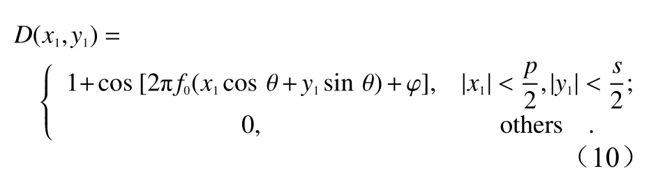
wherepis the slit width;sis the length of line spot on the CCD,and is infinitely small when being analyzed in the above line-scanning PSF model.Based on the line-scanning mode,this paper mainly studies the characteristics of coherent imaging in the system when the detection function is as shown in Eq.(10).Since only the super-resolution information in the current scanning direction can be extracted under the single-line-scanning condition,the Eq.(5)can be rewritten into(when only one dimension,namelyx-axis,is considered):

By substituting the Eq.(10)into Eq.(11),the Fourier transform of Eq.(11)will be
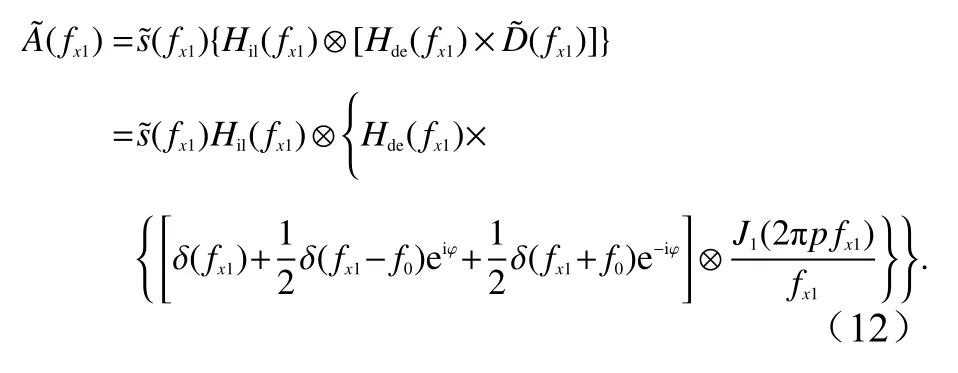


whereUc(fx1)is low frequency component,andUl(fx1)andUr(fx1)are high frequency components.They can be easily determined from Eq.(13).
3 Computational simulation
The laser wavelength λof the simulated lighting is 488 nm,the numerical aperture of the objective lens is 0.4,the cosine function modulation frequencyf0is 0.9NA/λ,and both θand φare 0.The scanning direction isXdirection,i.e.,0°direction.The extreme case is assumed,i.e.the slit widthsis infinitely small.The IPSF simulating the normal line-scanning confocal imaging in accordance with Eq.(8)is shown in Fig.2(Color online).According to Fig.2(c),the Full Width at Half Maximum(FWHM)in theXdirection decreases to 0.71 times of the FWHM in theYdirection,because of the confocal imaging in theXdirection and the wide-field imaging in theYdirection.It can also be seen from the OTF in Fig.2(b)that the cut-off frequency in theXdirection is higher than that in theYdirection,so the ability to transmit high-frequency information is enhanced.
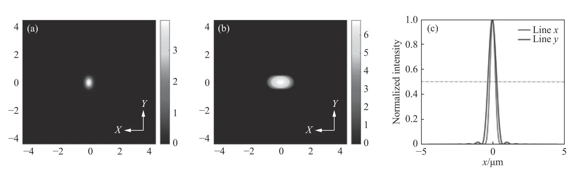
Fig.2 Theoretical simulation results of IPSF.(a)IPSF of traditional line-scanning confocal microscope;(b)Fourier transform of IPSF;(c)normalized intensity distributions of(a)in theXandYdirections respectively图2 IPSF 理论仿真结果。(a)普通线扫描共聚焦显微镜的IPSF,(b)IPSF 的傅立叶变换,(c)图(a)中X 和Y 方向上的归一化强度分布
The simulation system CTF based on Eq.(7)is shown in Fig.3(Color online),where the slit width is equal to an Airy disk.It can be seen from Fig.3(c)that,compared with Wide-field Microscopy(WM),the cut-off frequencies of CLSM and LVSM in the direction of image scanning are both twice that of WM,indicating higher resolution in the corresponding spatial domain.Given the same cut-off frequency,the percentage of high-frequency information in LVSM is significantly higher than that in CLSM.This indicates that LVSM has a stronger capability of high-frequency information transfer.This is attributed to the modulation of cosine function,which increases the high-frequency ratio.
In the structure detection method based on linescanning confocal imaging,the structure detection functionD(x,y)directly acts on the unscanned image of the detector plane and doesn’t need to be conjugated with the sample,and the detection function image remains unchanged.The difference between this method and VSD super-resolution method is that,in the VSD method,the structure detection function acts on non-unscanned images,but the imaging system itself is unscanned,so the structure function images need to be conjugated with the sample in order to achieve the effect of non-unscanning modulation and obtain the image data similar to wide-field SIM.In VSD,the reconstruction algorithm identical with wide-field SIM is used to move high-frequency information to the right place,in order to achieve the super-resolution effect.However,in the above method,the unscanned images under line-scanning confocal condition are directly modulated by the detection function,and the cut-off frequency of the system CTF is extended without frequency shift.Even without subsequent image processing,the image resolution is still improved.However,the problem of low transmittance of high-frequency information,as shown in the red curve in Fig.3(c),still exists,so the improvement effect is not obvious.As shown in Fig.4,we can change the phases of the modulation function,establish an equation like Eq.(13),calculate the frequency components along these directions,use the Wiener filtering algorithm to reduce noise,and then apply the generalized Wiener filter to perform weighted superposition recovery of the processed frequency domain information in order to enhance the high frequency components.When the generalized Wiener filter is used for weighted superposition,the weight factor of each frequency component mainly depends on its SNR,which can be estimated with the method in Ref.[19].After the frequency domain image weighted and superimposed enters the spatial domain through inverse Fourier transform,the finally reconstructed amplitude image can be obtained.Then through square operation,the intensity image can be obtained.
Since line-scanning confocal imaging is working only in one direction,the specific detection function can only expand the cut-off frequency of CTF in a single direction of the system.In order to illustrate the feasibility of isotropic resolution improvement,the image field needs to be rotated to obtain the line-scanning data in different directions for virtual modulation.The more the modulation directions are,the more obvious the isotropic resolution improvement will be.Meanwhile,the imaging speed rate will be reduced,but still much higher than that in the point-scanning mode.An appropriate modulation direction can be selected according to the actual situation.The line spot image obtained in each scanning position is modulated by the structure detection function,and the integral of the images within the linear spot in one direction is calculated to obtain a series of values representing the current scanning positions.These values and their positions represent the structurally modulated image and are used in the subsequent reconstruction process.Because the modulation mode is virtual modulation and the direction and phase of the digital mask can be accurately known,the estimated error of modulation mode and phase will not exist.
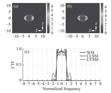
Fig.3 System CTF simulation.(a)CTF of traditional confocal line scanning microscopy(for CLSM);(b)CTF of line-scanning confocal microscopy with structure modulation(for LVSM);(c)black curve is the normalized frequency distribution along theYdirection in(a)(for WM),and blue and red curves are the normalized frequency distributions along theXdirection in(a)and(b),respectively(for CLSM and LVSM)图3 系统CTF 仿真。(a)传统线扫描共聚焦(CLSM)的CTF,(b)线扫描结构调制共聚焦(LVSM)的CTF,(c)黑色曲线为(a)中Y 方向归一化频率分布(WM),蓝色和红色曲线分别为(a)、(b)中X 方向归一化频率分布(CLSM、LVSM)
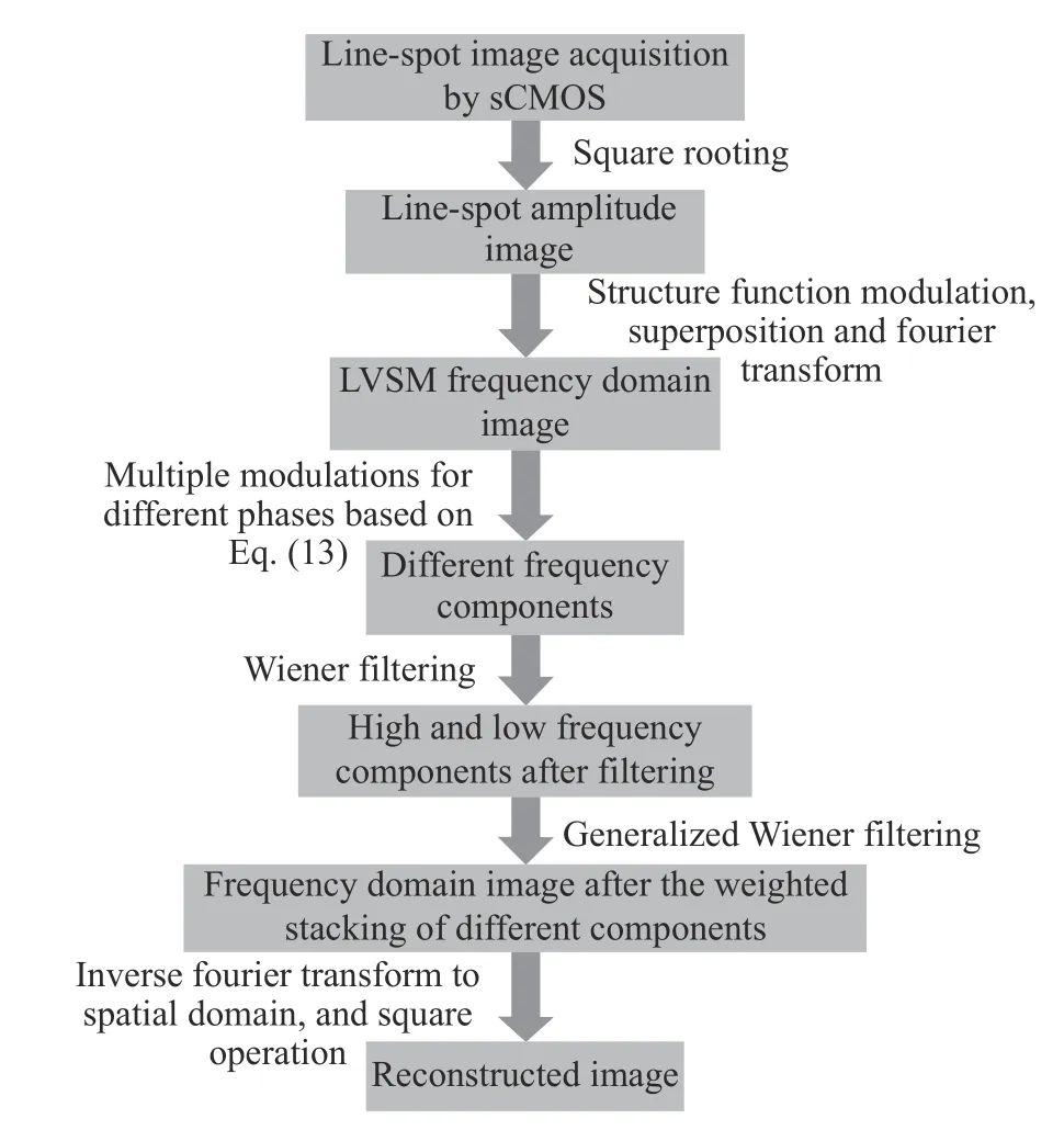
Fig.4 Flow chart of image reconstruction图4 图像重建过程流程图
To demonstrate the effectiveness of the above method,the imaging results of LVSM were simulated,as shown in Fig.5(Color online).The scanning directions of each sample were 0°and 90°.It can be seen from Fig.5(e)and Fig.5(f)that part of the high-frequency information is cut off,and the detail information of the sample is lost.After the LVSM reconstruction,the high-frequency information in the corresponding direction is moved into the frequency domain passband of the system and put in the right place,and the frequency spectrum in the scanning direction is expanded.It can be seen from the comparison between Fig.5(b)and Fig.5(c)that,after an image in the frequency domain is moved into the spatial domain through transformation,its resolution is significantly improved.
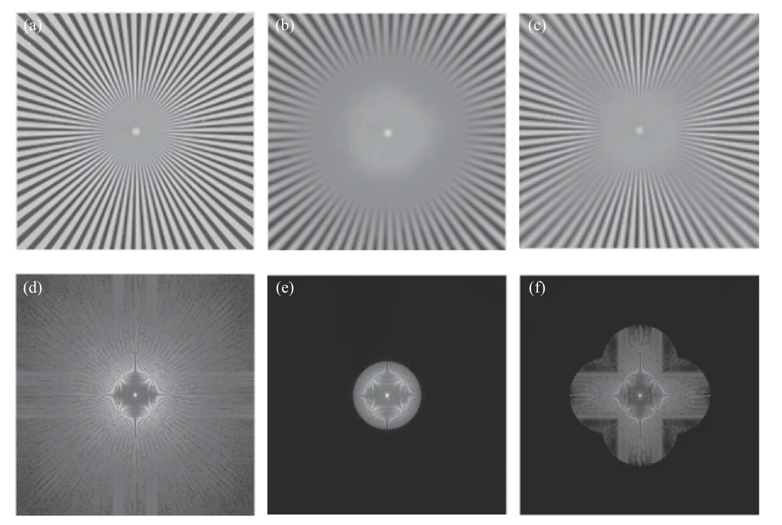
Fig.5 Simulation of line-scanning confocal microscopy with virtual structure modulation(for LVSM).(a)Spoke-like sample for simulation;(b)image of conventional confocal microscopy;(c)image reconstructed with the structure detection functions in the two scanning directions of 0°and 90°;(d),(e)and(f)are the Fourier transforms i.e.frequency domain images of(a),(b)and(c),respectively图5 线扫描共聚焦虚拟结构调制仿真(LVSM)。(a)仿真使用的辐条状样品。(b)普通共聚焦图像。(c)取0°、90°两个扫描方向,结合对应方向上的结构检测函数重建后图像。(d)、(e)、(f)分别是(a)、(b)、(c)的傅立叶变换,即对应的频域图像
4 Experiments and results
4.1 Experimental system
The LVSM based on laser line-scanning structure detection is shown in Fig.6.In the LVSM,a single-mode He-Ne laser with a wavelength of 633 nm is used to generate the polarized laser,and an optical attenuation is used to reduce the light intensity.The cylindrical lens CL(f=180 mm)has the focusing characteristic only in one direction,focusing the attenuated laser into a line of light that will be incident to a uniaxial scanning galvanometer(Mode 6215 CTI).The scanning galvanometer vibrates in the scanning direction to guide the focusing line through the homemade scanning lens,tube lens(TTL 180-A Olympus)and objective lens until the line moves along the specified direction on the sample.To reduce the vignetting effect,the center of the galvanometer is controlled to conjugate with the pupil plane of the objective lens.The light reflected from the sample is unscanned by one-dimensional scanning system and relayed to the image plane via the intermediate optical system.The detector collects the line spot images from the current scanning position.As the scanning galvanometer swings,the position of the unscanned image on the detector plane remains unchanged but the image information is constantly updated.512 line-spot images are continuously collected from different scanning positions to obtain a two-dimensional image.
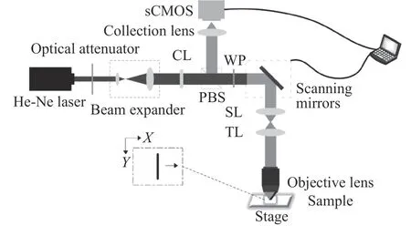
Fig.6 Schematic diagram of experiment setup图6 实验系统示意图
sCMOS,a two-dimensional image acquisition device,is used to acquire a single line-spot image(ORCA Flash4.0 V2,Hamamatsu).Compared with EMCCD,the sCMOS has higher quantum efficiency and lower noise output.When the ROI of line-spot image is set as 512 pixel×64 pixel,the theoretical image acquisition rate in a single direction can reach 3 206 fps.In the actual experiment,considering the response time of the device and the delay of the program,the image acquisition rate will decrease,and the image acquisition time in a single direction will be about 0.25s.The width of virtual slit is assumed to be the diameter of Airy disk and is used to detect and process the collected images.
A 4×flat-field semiapochromat(Olympus)with a numerical aperture of 0.13 is used.The experimental sample is a target with standard optical resolution(USAF 19511×,Edmund).To verify the enhancement of final isotropic resolution,an electric rotary translation stage with the maximum rotation rate of 50°/s is driven by a stepper motor to rotate the sample.The directions of image acquisition are 0°and 90°,and the time for the whole image rotation process is about 2s.
4.2 Experimental results
Some of the acquired line-spot images and the final image reconstruction results are shown in Fig.7(Color online).
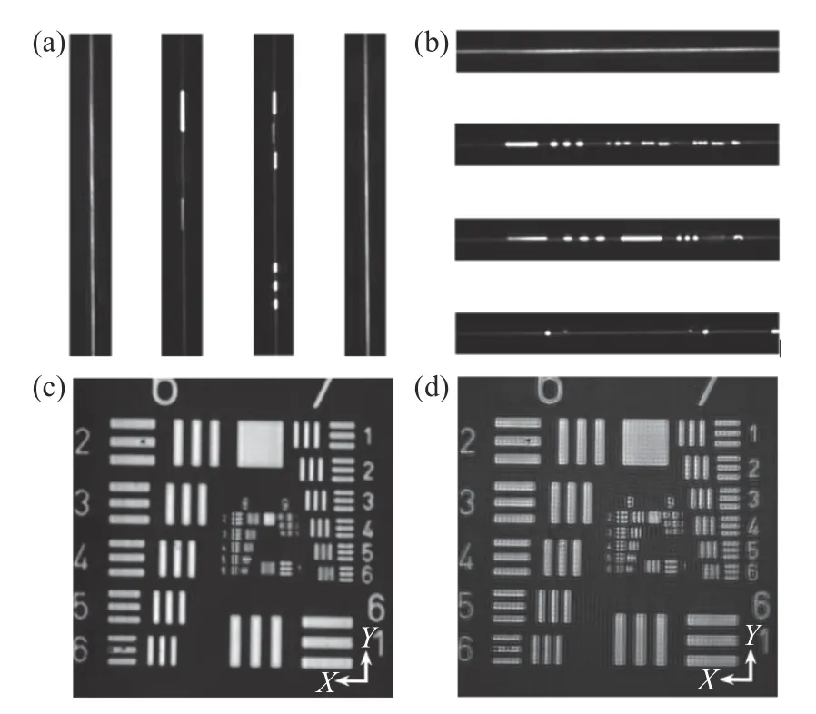
Fig.7 Implementation of line-scanning confocal virtual structure modulation imaging on the resolution test target.(a)The 20th,205th,360th and 490th line spot images collected in the 0°scanning direction;(b)the 20th,205th,360th and 490th line spot images collected in the 90°scanning direction;(c)the image of resolution test target obtained by conventional line-scanning confocal method in the 90°scanning direction;(d)reconstructed super-resolution image by LVSM图7 分辨率测试目标的线扫描虚拟结构调制共聚焦实现。(a)扫描方向为0°时,采集的第20、205、360、490 条线斑图像。(b)扫描方向为90°时,采集的第20、205、360、490 条线斑图像。(c)扫描方向为90°时,常规线扫描共聚焦获得的分辨率测试靶图片。(d)LVSM 超分辨重建后图像
The areas marked by blue line segments are the No.8.2~8.6 line pairs in theYdirection of the resolution test board,the area marked by yellow line segment is the No.8.5 line pair in theXdirection,and the area marked by green line segment is the No.8.6 line pair.It can be seen from Fig.8(a)(Color online)that in theYdirection,a conventional line-scanning confocal microscope can distinguish the No.8.2 group but cannot distinguish the No.8.3 group.The number of line pairs in the No.8.2 group is 287 lp/mm,and the corresponding spatial period is 3.48μm.The LVSM microscope can distinguish the No.8.5 group but cannot distinguish the No.8.6 group.The number of line pairs in the No.8.5 group is 406 lp/mm,and the corresponding spatial period is 2.46μm.The resolution of LVSM microscope is higher than that of a line-scanning confocal microscope with the same slit size.As seen from Fig.8(b)(Color online)and Fig.8(c)(Color online),in theXdirection,the line-scanning confocal microscope cannot distinguish both the No.8.5 and No.8.6 groups.In comparison,the LVSM can distinguish the No.8.5 group but cannot distinguish the No.8.6 group.Therefore,the resolutions of LVSM in both theXandYdirections are improved to 2.46μm,1.4 times that of traditional line-scanning confocal microscope.
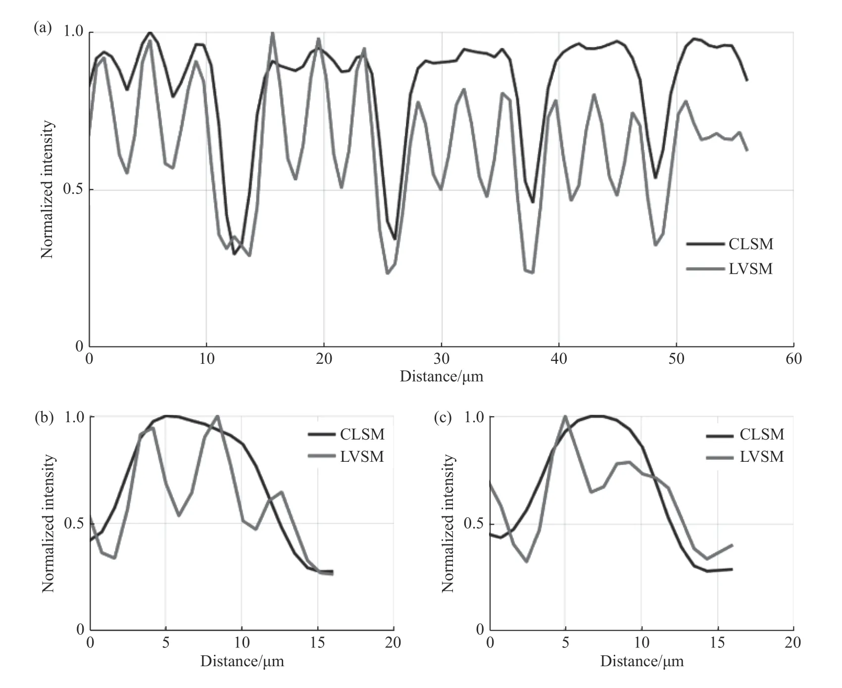
Fig.8 Normalized intensity curves of conventional line-scanning confocal microscope and line-scanning confocal microscope with virtual structure modulation in specified areas.Comparison between the normalized intensities of the area marked by(a)blue curve,(b)yellow curve and(c)green curve in Fig.7(c)and Fig.7(d)图8 常规线扫描共聚焦和线扫描虚拟结构调制共聚焦在特定区域的归一化强度曲线。图7(c)、7(d)中(a)蓝色线段标记区域(b)黄色线段标记区域及(c)绿色线段标记区域的归一化强度分布对比
The above experiment demonstrates that the LVSM can break the diffraction limit during highspeed imaging.This theory shows that the LVSM can improve the lateral resolution and imaging speed by using the modulation factors in two directions.The experiment with standard resolution target confirms that in addition to performing the line scanning based on high-speed imaging,the LVSM microscope can show the detailed target structure that can’t be detected by conventional confocal microscopy.
5 Conclusion
In this paper,a line-scanning confocal microscopic imaging method based on structural modulation is presented.The related theories and reconstruction methods are deduced and verified by experiment.The results of simulation and experiment show that the system CTF is enlarged and the imaging resolution is 1.4 times that of traditional confocal microscope.Compared with the point-scanning spot imaging with virtual structure modulation,the imaging rate of the system can be greatly improved in this method.This method needs 2.5 s to scan the image with 512 pixel×512 pixel in two directions,104 times faster than the former method,which needs about 260 s to complete the image acquisition under the image field of the same size.
——中文对照版——
1 引言
由于光波衍射效应的存在,传统光学显微镜的分辨率受到限制[1-2]。激光扫描共焦显微镜(LSCM)具有比宽场显微镜更高的分辨率。因为它使用紧密聚焦的激发光束和针孔检测来抑制离焦背景光[3-4]。但是受到针孔大小的限制,在共焦显微镜中,减小针孔的尺寸在提高分辨率的同时也降低了信噪比。为了保持二者的平衡,针孔尺寸一般较大,这会导致横向分辨率低于理想结果,仍处于衍射极限之内[5-6]。……
登录APP查看全文
猜你喜欢
工业设计(2022年8期)2022-09-09 07:43:20
计算机应用(2022年2期)2022-03-01 12:33:42
哲学评论(2021年2期)2021-08-22 01:53:34
计算机应用(2021年4期)2021-04-20 14:06:36
军民两用技术与产品(2021年10期)2021-03-16 06:05:30
计算机应用(2021年1期)2021-01-21 03:22:38
北京测绘(2020年12期)2020-12-29 01:33:58
中华诗词(2019年7期)2019-11-25 01:43:04
家庭影院技术(2017年9期)2017-09-26 03:41:45
影视与戏剧评论(2016年0期)2016-11-23 05:26:01

- 中国光学的其它文章
- Enhanced dye-sensitized up-conversion luminescence of neodymium-sensitized multi-shell nanostructures
- Polarization changes of partially-coherent Airy-Gaussian beams in a slanted turbulent atmosphere
- Hybrid plasmonic leaky-mode lasing on subwavelength scale
- 10−9 量级高灵敏度点源透射比测试设备研究
- 大孔径静态干涉成像光谱仪径向畸变导致的谱线偏移误差的校正
- 表面损伤衍射双向反射分布函数模型建立及分析