
Programmable electron density patterns induced by the interaction of an array laser and underdense plasma
2021-05-22 07:00XiaoboZHANG张小波XinQIAO乔鑫AixiaZHANG张爱霞andJukuiXUE薛具奎
Plasma Science and Technology 2021年5期
Xiaobo ZHANG (张小波), Xin QIAO (乔鑫), Aixia ZHANG (张爱霞) and Jukui XUE (薛具奎)
College of Physics and Electronics Engineering,Northwest Normal University,Lanzhou 730070,People’s Republic of China
Abstract The spatially modulated electron distribution of plasma is the basis for obtaining programmable electron density patterns.It has an important influence on plasma technology applications.We propose an efficient scheme to realize controllable electron density patterns in underdense plasma based on the array laser–plasma interaction.Theoretical evidence for the realization of programmable electron density patterns and the corresponding electrostatic field is provided analytically, which is confirmed by particle-in-cell simulations.Results show that the spatial distribution of electron density in the propagation and transverse directions of the laser can be highly modulated to obtain rich programmable electron density patterns by adjusting the array pattern code and pulse width of the array laser beam.
Keywords: laser–plasma interactions, electron density, particle-in-cell
1.Introduction
A number of nonlinear effects are observed in intense highfrequency electromagnetic waves and plasma interactions.These effects are closely associated with the ponderomotive force of lasers and the surface structure of media [1–4].In general,the ponderomotive force is a nonlinear force resulting from the longitudinal and transverse spatial variation of the laser’s intensity [5–10].It impacts the charged particles in plasma.Ponderomotive force plays an important role in many physical phenomena, such as electron cavitation, x-ray generation, intense magnetic-field generation, shock generation and electron and ion acceleration [5, 11–15].Compared with the ponderomotive force effect of the interaction between a laser and a planar target, recent studies have found that structure targets with good geometric designs(such as microchannel targets [16–20], nanowire arrays [21, 22] and other structured targets[23–25])can further enhance the interaction of lasers and targets.A significant increase in cut-off energy and electron number has been realized via effective interactions between the laser and the micro-channel structure, which can be an excellent electron source for Bremsstrahlung x-ray and THz radiation generation [16–18, 20].The energy and flux of electrons have been improved by the interaction of lasers and nanowire arrays [21, 22].Moreover,the plasma grating induced by the interference effects of multiple filaments of lasers in air has an important influence on the energy transfer of laser pulses [26–28].Although the temperature and maximum kinetic energy of electrons can be greatly enhanced through the interaction of lasers and some special structural targets, the secondary application of structural targets has been proposed due to the limitations of the damage threshold of materials [16, 20, 21].Plasma spatial structures with well-aligned and highly ordered arrays can be considered as prospective candidates in high-intensity laser applications, such as particle acceleration and microwave emission,in contrast to the specific and low damage threshold of the solid structure target [16, 17, 20, 29–31].
At present, the realization and modulation of plasma spatial structures based on the interaction between lasers and plasma have attracted a great deal of attention owing to their wide advantages of efficiency, tunability and no damage threshold.The electron density profile of plasma is modified by the ponderomotive force and the relativistic dependence of electron mass on the electron velocity,which corresponds to the generation of space charge and wakefields[5,32].The magnetic field profile and plasma density cavitation in intense laser–plasma interactions have been discussed theoretically [32].The profile of the electric field, magnetic field and electron density in collisionless nonisothermal plasma has been investigated by considering the ponderomotive force [5].The grating structure of electron density distribution at the surface of the uniform plasma generated by two intersecting laser beams has been studied theoretically [33].The distribution of electron and ion density with the periodical distribution induced by two intersecting laser beams has been explored theoretically [34–36].Those studies mainly focus on two aspects.First, the modulation of the electron density is mainly in the direction of the laser’s propagation to control the space-charge field and the dielectric permittivity of plasma [32, 37, 38]; second, the control of the crossing angles of two intersecting laser beams is necessary to obtain plasma density distribution by using a grating structure [33, 35, 36].Obviously, the multi-dimensional modulation of electron distribution to obtain microscale structures with a well-aligned and highly ordered array is still challenging.In addition, the survival time of these micro-scale structures in plasma is a critical issue for their potential applications [27].
In this paper, we analytically demonstrate a scheme for generating two- and three-dimensional programmable electron density patterns through an array laser–plasma interaction in a uniform and cold plasma.Further, the analytical solutions are confirmed by particle-in-cell (PIC)simulations with the software VSim[39].The application of array laser beams in laser–plasma interactions is of practical importance and necessity,which will result in the generation of spatially modulated plasma structures.Usually,the phaselocking of the waveguide linear array [40–42], the off-axis pumping mechanism of the half-symmetric laser resonator[43,44],and a tiled fiber laser array[45]are used to build up the array laser beam.By adjusting the array pattern code and pulse width of array laser beams, the transverse and longitudinal spatial distribution of the electron density is highly modulated and controlled.Spatially modulated electron density structures with multiple distribution patterns are realized.
In section 1, we show the introduction and the key application of this work.In section 2,we provide a theoretical basis for the realization of the programmable electron density patterns and find that the spatial structure of the electrons’density mainly depends on the profile and pulse width of the laser.In section 3,based on the theoretical results and the PIC simulation results,we confirm the generation and modulation of the different spatial distribution of the electrons’ density and the corresponding electrostatic field.
2.Model and theoretical analyses
We consider Gauss and super-Gauss array laser beams with angular frequency (ω) and wave vector (k), which are polarized along they-direction and co-propagating in thez-direction in the uniform cold plasma.In this case,the electric field of the super-Gaussian array laser beam as felt by the underdense plasma can be given by:

whereE0Lis the laser field amplitude,α(y)=is used to specify the beam profile,bwis the beam width,d=2bwis the array separation distance andqis a variable known as the super-Gaussian (SG) index.mis the array pattern code of the array laser beam.β(t)=sin(tπτ0)2and τ0are the pulse width.The basic equation of motion for the cold electron plasma is:

where A is the electromagnetic vector potential and satisfies the condition ∂A/∂t=−m0c2E/e, φ is the electrostatic scalar potential.cis the speed of the light andeis the electronic charge,m0is the electronic mass.p=γm0v is the momentum of the electrons, whereis the relativistic factor.Using the equality (v·∇)p=m0c2∇γ −v×(∇×p) and combining equations (1) and (2),one obtains ∇×(p −e/cA)=0.Meanwhile,because the highfrequency oscillating component of the laser only causes the electrons to shiver, we neglect the effect of the high-frequency oscillating component of the laser on the plasma density.Therefore, we can write:

Because the mass of an ion is larger than that of an electron,the ion only forms a uniform background without any movement.The density of the electron’sNis expressed as the sum of the uniform equilibrium valueN0and the perturbed one ′N,i.e.,N=N0+N′.Through the electron continuity equation∂N/∂t+∇(Nv)=0 and Poisson equation∇2φ=4πe(N−N0),whereNandN0are the densities of the electrons and ions,respectively, the perturbed equations can be reduced to the following form:

Combining equations (3), (4) and (6), one obtains:

where the ponderomotive forceFpimpacted on an electron in the presence of an intense electromagnetic beam can be represented asFp=−m0c2∇(γ −1).With the help of the perturbed Poisson equation(5),the perturbed term in the electron density equation, i.e., ′N, can be expressed as:

Figure 1.Phase diagram of the transverse electron density and the ponderomotive force generated by the different type and intensity of the laser.(a) Gauss laser with q=2, m=0;(b) super-Gauss laser with q=6, m=0;(c) Gauss array laser beam with q=2, m=1; and(d) super-Gauss array laser beam with q=6, m=1.τ0=10 fs.

where ωpis the plasma frequency.The initial velocity of the electrons is zero because the plasma is cold.The product( ′Nv)of the perturbed electron density and velocity is a small second-order quantity and can be neglected.In the steady state,the perturbed term in the electron density equation can be reduced to:

Thus, the total electron density is represented byN=N0+N′.Clearly, the electron density distribution of the plasma depends on the ponderomotive forceFpand the gradient of the ponderomotive force,which is modulated by the spatial structure and pulse width of the Gauss and super-Gauss array laser beam.The spatially modulated plasma structure with multiple plasma distribution patterns can be realized effectively.
According to equation (9), the phase diagram of the electron density distribution of the plasma and the transverse ponderomotive force generated by the different type and intensity of the laser is shown in figure 1.The frequency of the laser ω=1×10¹⁶rad·s−1and the beam width of the laserbw=1 μm, which can be obtained by the argon fluoride laser source [46].The plasma frequency ωpe=1.1×10¹²rad·s−1and the initial density isN0(=4×10²⁰m−3).The other parameters have been written in the dimensionless form by using the scalings:t~t/ω−1,r(x,y)~r(x,y)/cω−1,n~N/N0, ωpe~ωpe/ω,E~Ee/m0ωpec.The black dashed line corresponds to the initial electron densityN0without the irradiation of the array laser beam.The different symbols on the solid line correspond to the different spatial distributions of the electron density irradiated by the different intensities of the array laser beam.For the Gauss laser beam(q=2,m=0),the electron density distribution inN–Fpplane shows a cardioid-shaped character,which includes two regions,i.e.,one with the density is lower(below the black dash line)and the other one with the density is higher (above the black dash line) than the initial electron density [figure 1(a)].The low-density region results from the ponderomotive force pushing the electrons to the edge of the laser, which also results in the formation of the high-density region at the edge of the laser.Because the ponderomotive force is continuous in space, the closed cardioid-shaped distribution of the electron density means the formation of one type of distribution pattern of the electron density, which is symmetrical about theFp=0.Due to the existence of the platform of the super-Gauss laser beam (q=6,m=0), the formation of the ponderomotive force only locates at the edge of the laser, which results in the significant split of the cardioid-shaped character of the electron density and the formation of the quasi-Bernoulli lemniscate-shaped character in theN–Fpplane [figure 1(b)].Clearly, the quasi-Bernoulli lemniscate-shaped character in theN–Fpplane includes two annular patterns,which means the formation of the two types of distribution patterns of the electron density.Moreover, the quasi-Bernoulli lemniscate-shaped character in theN–Fpplane is symmetric about theFp=0, which means that the two types of distribution patterns of the electron density are symmetric about the spatial location of theFp=0.

Figure 2.Variation of the electron density against the spatial coordinate r(y,z)at the time of 0.7×10³.The first(second)row for theoretical(PIC simulation) results.The first (second) column for the q=2 (q=6) results with the array pattern code m=0.The electron density against the transverse coordinate y at z=0.2 when the laser is a Gaussian laser (e) and a super-Gaussian laser (f).τ0=10 fs, E0L=0.03.
Interestingly,the cardioid-shaped and the quasi-Bernoulli lemniscate-shaped characters in theN–Fpplane are significantly modified by the array laser beam with the array pattern codem=1 [figures 1(c) and (d)].Clearly, the central region of the cardioid-shaped character in theN–Fpplane has two new closed annular patterns whenm=1 andq=2[figure 1(c)].Accordingly, the three distribution patterns of electron density will be generated completely.However, the structures of the two new closed annular patterns have similar structures, which means the formation of two types of distribution patterns of electron density.When the array laser beam is a super-Gauss laser array (m=1,q=6), the quasi-Bernoulli lemniscate-shaped character in theN–Fpplane is modified by the formation of one new closed annular pattern in the central region of the quasi-Bernoulli lemniscate,which means the formation of a new distribution pattern[figure 1(d)].Particularly, the closed annular pattern generated by the array laser beam has a different structure with the generation of the high electron density at the location ofFp=0.In addition to the effects of the different array laser beam, the intensity of the laser will have positive effects on the structure of the electron density.WhenE0L=0.03, the intensity of the ponderomotive force can reach 0.08 pN and the electron density difference between the high-density region and the low-density region is only 0.1 (i.e.,0.4×1020m−3).WhenE0L=0.09, the intensity of the ponderomotive force can reach 0.31 pN and the electron density difference between the high-density region and the low-density region can be close to 0.4 (i.e., 1.6×10²⁰m−3).The different profile of the laser array beam also affects the electron density difference between the high-density region and the low-density region [figures 1(a) and (b)].However,the array pattern code of the array laser beam only changes the spatial distribution and does not affect the difference value of the electron density between the high-density region and the low-density region [figures 1(a) and (c)].The initial electron density can be modulated by adjusting the type and intensity of the laser, which results in the generation of programmable electron density distribution.
3.Generation and modulation of the electron density patterns
3.1.Density patterns of the electrons generated in the polarization plane of the laser

Figure 3.Variation of the electron density against the spatial coordinate r(y,z)at the time of 0.7×10³.The first(second)row for theoretical(PIC simulation) results.The first (second) column for the q=2 (q=6) results with the array pattern code m=0.The electron density against the transverse coordinate y at z=0.2 when the laser is Gaussian laser (e) and super-Gaussian laser (f).τ0=1 fs, E0L=0.03.
To support the above theoretical predictions, we perform PIC simulations.First, the density patterns of the electrons in the polarization plane of the laser are discussed.The 2D PIC simulation is performed with the length of 1.3×10²and width of 4.6×10²(i.e.,4×14 μm2)with 400×700 cells,resolving each 2△z=△y=0.6 and △t=8.7×10⁻²(i.e., 8.7 as).Each cell contains 2×2 macro-particles representing the ensemble of real charged particles.Figures 2(a)–(d) show the electron density of the plasma in they–zplane generated by the long laser pulse(τ0=10 fs)when the time is 0.07 ps.The theoretical results(the first row)are in good agreement with the PIC simulations (the second row).Figures 2(e) and (f) show the corresponding distribution of the electron density in the transverse direction when the longitudinal coordinatezis 0.2×10²intuitively.Clearly,the electrons near the axis of the Gauss laser are pushed out to the edge of the Gauss laser(q=2), which results in the generation of two high electron density boundaries at the edge of the Gauss laser and a lowdensity region with width of 0.5×10²[figures 2(a) and (c)].Figure 1(e) shows that the center of the low-density region is coincident with the axis of the laser and the high-density region is symmetric about the center of the low-density region,which is predicted in figure 1(a).Interestingly,the low-density region will be separated into two narrower low-density regions with width 0.1×10²by the super-Gauss laser (q=6) [figures 2(b)and (d)].Each low-density region of the plasma has only one high electron density boundary (rectangular frame), which is located at the edge of the laser.The uniform region of the plasma is formed near the axis of the laser without any significant variation of the electron density.The boundaries of the low-density region are not symmetric about the center of the low-density region [figure 1(f)].However, the two density regions are symmetric about the axis of the laser corresponding to the ponderomotive forceFp=0, which is predicted in figure 1(b).The quantitative deviation between the theoretical results and the PIC simulations is caused by the local deformation and focusing of the lasers in the PIC simulation,which are not considered in the theoretical model.
In fact,the transverse ponderomotive force mainly arises from the inhomogeneous optical field in the transverse direction, which results in the transverse modulation of the electron density and the generation of the different distribution patterns of electron density.However, the longitudinal ponderomotive forceF||from the inhomogeneous characteristic of the pulse envelope has a significant effect on the spatial distribution of the electron density when the pulse width of the laser is short enough, i.e.the longitudinal ponderomotive force of the laser will push the electrons to the propagation direction of the laser.With the passing of time,many laser pulses pass through the plasma.An electrostatic fieldEis generated and increases gradually, which results from the charge separation of the electrons and ions.WheneE||=−F||, the electrons will not be pushed byF||and the structure of the electrostatic field can be maintained.Because the laser propagates along thez-direction, the structure of the electrostatic field will be generated periodically, which corresponds to the formation of the periodic spatial distribution of the electron density [figures 3(a)–(d)].The significant slow-wave structure of the electron density forms near the region of the axis of the laser.The wave vector of the slow wave can be adjusted by changing the pulse width of the laser withk≈(cτ0)−1.Due to the formation of the slow-wave structure located at the axis of the laser,there is a strong effect on the low-density region of the electron density generated by the Gauss laser [figures 3(a) and (c)].Figure 3(e) shows the distribution of electron density at different longitudinal locations.When the longitudinal location isz=0.14×10²,there is a significant low-density region located at −0.35×10²<y<0.35×10².When the longitudinal location isz=0.2×10², the density of the electrons is modulated with the formation of two density peaks located at −0.35×10²<y<0.35×10², which is symmetric about the center of the low-density region and the axis of the laser.However, there is a weak effect of the slow wave on the distribution of the low-density region located at 0.12×10²<|y|<0.23×10²when the laser is the super-Gauss laser beam [figures 3(b), (d) and (f)].However, the uniform region between the two low-density regions is also strongly affected by the slow wave [figure 3(f)].The density of the uniform region located at −0.12×10²<y<0.12×10²increases significantly atz=0.2×10².However, the density of the uniform region will be close to the density of the low-density region atz=0.14×10²,which results in the combination of two low-density regions and the amplification of the range of the low-density region.Because the transverse ponderomotive force is larger than the restoring force of the charge separation, the slow wave is only a longitudinal distribution of the electron density, which is not the classic plasma wave.The PIC simulation shows that the electron density of the middle region has a filamentous structure,which is caused by the filamentation of the super-Gauss laser propagating in the uniform plasma.

Figure 4.Variation of the electron density against the spatial coordinate r(y,z)at the time of 0.7×10³.The first(second)row for theoretical(PIC simulation) results.The first (second) column for the q=2 (q=6) results with the array pattern code m=1.The electron density against the transverse coordinate y at z = 0.2 when the laser is a Gaussian laser (e) and a super-Gaussian laser (f).τ0=1 fs, E0L=0.03.
In the above studies, the effect of the inhomogeneous optical field and the pulse width on the distribution of the electron density is studied by theoretical analysis and PIC simulations.Clearly, the modulation of the profile and duration of the lasers can effectively control electron density to realize different plasma structures in the transverse and longitudinal directions.By using an array laser beam, the multiple distribution of the electron density in the transverse direction is also realized.The modulation of the longitudinal distribution of the electron density still depends on the longitudinal ponderomotive force of the laser pulse.The coupling effects of the array laser beam and the slow wave on the distribution of the electron density are shown in figure 4.There are three low-density regions and four high-density regions when the uniform plasma is irradiated by a Gauss array laser beam [figures 4(a)and(c)].The three low-density regions are located aty=±0.5×10²and 0 when the longitudinal coordinate is 0.14×10², respectively [figure 4(e)].Clearly,there are two low-density regions near the edge of the array laser beam with similar structures,which is also verified in figure 1(c) by the two similar closed annular patterns.The four high-density regions are located aty=±0.25×10²and±0.75×10²when the longitudinal coordinate is 0.2×10², respectively [figure 4(e)].In particular, the low-density regions and high-density regions make up the classical density well and density peak of the micro-scale electron structure.Clearly, the transverse modulation of the array laser beam also affects the slow-wave structure of the electron density, which results in the realization of a micro-scale electron structures with a well-aligned and highly ordered array.The density well is surrounded by four density peaks and four density walls and the intensity of the longitudinal density wall is stronger than that of the transverse density wall.For the micro-scale electron structure generated by the super-Gauss laser, the density well is still generated and surrounded by the same density peak and the different density wall [figures 4(b) and (d)].

Figure 5.Variation of electron density against the spatial coordinate (x, y, z) generated by the laser with (a) q=2, m=0;(b) q=6,m=0;(c) q=2, m=1; and (d) q=6, m=1.τ0=1 fs, and E0L=0.09.
The three low-density regions and four high-density regions are still generated effectively, which make up the density well and density peak of the micro-scale electron structure.Particularly,the high-density region atz=0.14×10²and the uniform density region atz=0.2×10²make up the density wall of the micro-scale electron structure[figure 4(f)].Clearly,the intensity and the width of the density wall atz=0.2×10²are greater than those of the density wall atz=0.14×10².Near the axis of the new low-density region, a region with high density is formed, which corresponds to the new closed annular in the central region of the quasi-Bernoulli lemniscate [figure 1(d)].The filamentous structure of the plasma density is more obvious than the filamentous structure of the plasma generated by them=0 array beam, which is caused by the asymmetrical transverse profile of the array laser beam.
3.2.Density patterns of the electrons generated in the threedimensional space
The three-dimensional (3D) PIC simulation is also provided to confirm the generation of the micro-scale structures with a well-aligned and highly ordered array.The physical dimensions for the 3D simulation are the length of 1.3×10², the width of 4.6×10²and the height of 4.6×10²(i.e.,4×14×14 μm3)with 400×700×700 cells,resolving each 2△z=△x=△y=0.6.The radius of the laser isr=0.33×10²and the intensity of the laser’s electric field is 0.09.Obviously, the distribution of the electron density in they–zplane also shows the significant slow-wave structure[figures 5(a)and(b)]and the array structure [figures 5(c)and(d)].However, the similar spatial distribution will not be generated in thex–zplane completely due to the lack of highdensity boundaries near the edge of the laser.Interestingly,the low-density region near the axis of the laser generated by the array laser beam withq=2 is modulated effectively to form a periodical spatial distribution in the propagation direction of the laser[figures 5(a)and(c)].For the array laser beam withq=6, in addition to the low-density region, the uniform region between two low-density regions is also modulated to form the periodical spatial distribution of the electron density in the propagation direction of the laser[figures 5(b) and (d)].When the laser beam (q=2, 6 andm=0) propagates through the plasma, the high-density region is generated near the (0, ±bw) in thex–yplane[figures 5(a) and (b)].When the super-Gaussian array laser(q=2, 6 andm=1) propagates through the plasma, the electron density is modulated to generate the higher density region near the (0, ±bw), (0, ±3bw) in thex–yplane[figures 5(c) and (d)].Because the array laser modulation plane is located in they–zplane,the high-density region near the(±bw,0)in thex–yplane will not generate a high-density region.It is clear that the electron density in thex–yplane can be modulated to generate the high-density region and the lowdensity region, which can also constitute the slow-wave structure in they-direction.
3.3.The survival time of the different electron density patterns

Figure 6.Variation of electron density near the axis of the laser against the time t and the longitudinal coordinate z generated by the laser with(a) q=2, m=0;(b) q=6, m=0;(c) q=2, m=1; and (d) q=6, m=1.τ0=1 fs, E0L=0.03.
In the previous sections, we discussed the multiple distribution patterns of the electron density theoretically and verified them by the PIC simulation.The scaling of the surviving time of the programmable electron structure is also a key issue for the application of the slow-wave structure and micro-scale electron structure designed by the well-aligned and highly ordered array.Figures 6(a)–(d)show the variations of electron density near the axis of the Gaussian laser (q=2, first column) and super-Gaussian laser (q=6, second column)against the timetand the longitudinal coordinatezwhen the array pattern codes are 0 (the first row) and 1 (the second row).For the case generated by the Gaussian laser [q=2,m=0 and 1, figures 6(a) and (c)], the longitudinal electron density does not appear to have the obvious periodic characteristic in the initial process(0 <t<0.4×10³).As the time increases (t≥0.4×10³), the electron density shows a periodic distribution along the propagation direction with the increase of the amplitude, which means the formation of the slow-wave structure and the micro-scale electron structure.However, because the array laser is not a relativistic one, the transverse ponderomotive force of the laser is greater than the transverse component of the electrostatic field force of the laser.Hence, although the electrons are not pushed to the propagation direction of the laser by the longitudinal ponderomotive force,the electrons located at the axis of the laser will be pushed to the edge of the laser by the transverse ponderomotive force of the laser continuously.Whent≥1.4×10³,the amplitude of the periodic distribution of the electron density is closer to zero, which results in the disappearance of the periodic distribution of the electron density and the formation of the plasma channel[figures 6(a)and(c)].The periodic distribution of the electron density can hold for the time of 1×10³(i.e., 0.1 ps) to generate the slow-wave structure withm=0 and the micro-scale electron structure withm=1.For the case generated by the super-Gaussian laser [q=6,m=0 and 1, figures 6(b) and (d)], the initial process is similar to the case generated by the Gaussian laser[figures 6(a) and (c)].Because the transverse ponderomotive force of the super-Gaussian laser is greater than that of the Gaussian one,the electrons are pushed to the edge of the laser more easily with the super-Gaussian laser, which causes the disappearance of the periodic distribution of the electron density when the time is greater than 1×10³[figures 6(b)and(d)].The periodic distribution of the electron density generated by the super-Gaussian laser can hold for the time of 0.6×10³(i.e., 0.06 ps) to generate the slow-wave structure withm=0 and the micro-scale electron structures withm=1.The survival time of the different electron density patterns generated by the different types of laser can be used effectively in electron acceleration and THz radiation[11–13, 25].
3.4.The corresponding electrostatic field Ez and Ey of the different electron density patterns
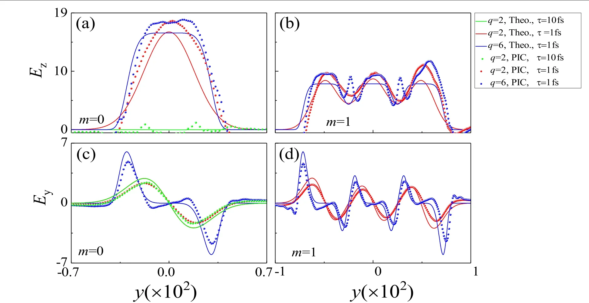
Figure 7.Variation of the Ez(the first row) and Ey(the second row) across the transverse coordinate y at z=0.18×10².The first (second)column for the array pattern code m=0 (m=1). t=0.7×10³, E0L=0.03.
Obviously, the generation of the micro-scale electron structure will result in the separation of the positive and the negative charge which leads to the formation of the electrostatic field.Figure 7 shows the transverse distribution of the electrostatic field (Ez,Ey) with the different pulse width and array pattern code atz=0.18×10²whent=0.7×10³.When the plasma is irradiated by the Gaussian laser beam with τ0=10 fs, the intensity ofEzis close to zero[figure 7(a)].However,Eyis generated with the opposite value on both sides of the laser axis, which means the direction of the electrostatic field points to the edge of the laser [figure 7(c)].Due to the two low-density regions generated by the super-Gaussian laser near the edge of the laser and the formation of the uniform density region near the axis of the laser,the correspondingEyis only generated during the range of 0.18×10²<|y|<0.5×10²[figure 7(c)].However,Ezwill be generated and modulated to form the Gaussian and the super-Gaussian distribution when the laser is short enough[τ0=1 fs, figure 7(a)].However, the distribution ofEywill not be affected by the short pulse,which still holds the similar structure generated by the long pulse [figure 7(c)].When the array laser beam is used to generate the micro-scale electron structure,Ezis also modulated to form the similar array Gaussian and super-Gaussian structures [figure 7(b)].However,an intensity peak located at 0.2×10²<|y|<0.32×10²is generated and is different from the theoretical results,which mainly results from the filamentous nature of the electron density.There are six intensity peaks ofEywith three positive values and three negative values,which are generated at different transverse space locations [figure 7(d)].Plasma structures with transverse electrostatic fields will have a positive effect on the improvement of electron energy [46].
4.Conclusion
In conclusion,based on the laser–plasma interaction,we have achieved an efficient scheme to generate programmable electron density patterns in a uniform and cold plasma.PIC simulations based on the scheme are also carried out to support the analytical results.The transverse and longitudinal spatial distributions of the electron density can be highly modulated and controlled by the array pattern code and pulse width of the array laser beam.A spatially modulated electron density structure with multiple distribution patterns is generated.Such powerful and simple modulation of electron density will pave the way toward realizing programmable electron density distribution.
Acknowledgments
This work is supported by National Natural Science Foundation of China (Nos.11865014, 11765017, 11764039,11475027, 11274255, and 11305132), the Natural Science Foundation of Gansu Province (No.17JR5RA076), and by the Scientific Research Project of Gansu Higher Education(No.2016A-005).
 Plasma Science and Technology2021年5期
- Plasma Science and Technology的其它文章
- Study of the tungsten sputtering source suppression by wall conditionings in the EAST tokamak
- Explicit structure-preserving geometric particle-in-cell algorithm in curvilinear orthogonal coordinate systems and its applications to whole-device 6D kinetic simulations of tokamak physics
- Comparison between fluctuation of floating potential gradient and velocity of blob structure on HL-2A tokamak
- Magnetic diagnostics for magnetohydrodynamic instability research and the detection of locked modes in J-TEXT
- Dielectric breakdown properties of Al-air mixtures
- Experimental investigation of the electromagnetic effect and improvement of the plasma radial uniformity in a large-area,very-high frequency capacitive argondischarge