
Design of optical wedge demodulation system for fiber Fabry-Perot sensor
2021-10-10 09:46:18ZHANGXiongxingLVWentaoZHANGTianyangKOUWanyingCHENQingqingWANGWei
中国光学
2021年5期
ZHANG Xiong-xing,LV Wen-tao,ZHANG Tian-yang,KOU Wan-ying,CHEN Qing-qing,WANG Wei
(School of Optoelectronics Engineering, Xi’an Technological University, Xi’an, Shannxi 710021, China)
* Corresponding author,E-mail: wangwei@xatu.edu.cn
Abstract: In order to realize the demodulation of the cavity length of the fiber-optic FP sensor, a new optical wedge-type non-scanning correlation demodulation system is proposed, and the characteristics and structure of the devices used in the system are analyzed and studied. First, by simulating the light sources with different spectral distributions and the optical wedges with different surface reflectivities, the correlation interference signals are analyzed and the optimal structure parameters of the system components are given. Then by comparing the light intensity distribution characteristics of the Powell prism and cylindrical lens on the linear array CCD, more uniform spectral distribution is achieved. Finally, the specific implementation scheme and data processing method of the demodulation system are given. The experimental results show that when the light source spectrum has a Gaussian distribution and large spectral width and the reflectivity of the wedge surface is R=0.5, the characteristics of the correlation interference signal are obvious and convenient for demodulation. Finally, the demodulation system achieves the demodulation effect with an error of less than 0.025% within the cavity length range of 60 μm-100 μm. This optical wedge-type non-scanning correlation demodulation method can realize the sensing demodulation of the fiber-optic FP cavity and improve the power adaptability of different types of fiber-optic FP sensors.
Key words: fiber-optic FP sensor; non-scanning correlation demodulation; optical wedge; Powell prism; linear array CCD
1 Introduction
As an important branch of optical fiber sensing,the technology of optical Fiber-optic FP sensor is developing rapidly. It is characterized by high precision, small size and anti-interference, and is widely used in aerospace, civil engineering, medical treatment and other fields[1-3]. The changes in external physical quantities will affect the cavity length of a FP sensor. By demodulating the cavity length information, different physical quantities such as pressure, temperature and strain can be measured[4-5].
Fiber-optic FP sensors are divided into intrinsic type and non-intrinsic type. The intrinsic fiber FP sensor is an internal cavity structure composed of optical fibers. It can sense the changes of external information by using the sensing of optical fiber.The non-intrinsic type, however, is an external cavity structure generally filled with air or vacuum and formed by hollow-core fiber, capillary, elastic membrane or other sensitive elements. These sensitive elements are used to sense the changes of physical quantities, while the optical fiber is only used for signal transmission[6-7]. Fiber-optic FP sensors can be fabricated by MEMS, chemical etching, direct welding, laser processing and other methods. With a simple structure and wide range of applications,they are of great significance for structural status detection under harsh working environment[8-10].
Due to the application advantages of FP sensors, the demodulation techniques for these sensors have also developed rapidly, mainly including intensity demodulation and phase demodulation[11]. Intensity demodulation is relatively traditional, and is easily interfered by external factors and optical device performance, which may result in low demodulation accuracy[12]. Phase demodulation is to calculate the cavity length according to the phase information of the obtained interference spectrum signal. It is less affected by the light intensity,so the demodulation accuracy is higher[13]. Correlation demodulation is to introduce a dynamic reference cavity into the demodulation system in accordance with the principle of cavity length matching,and then obtain the cavity length information through the correlation operation between the output signal of FP sensor and the reference cavity signal. According to the control mode of reference cavity, the demodulation techniques can be divided into scanning demodulation and non-scanning demodulation. In the scanning demodulation system,piezoelectric ceramics or a mechanical moving part is generally used to control the length of the reference cavity. In this scheme, the introduction of dynamic tuning signal and mechanical part often leads to low demodulation rate and low accuracy. The non-scanning demodulation system, however, is based on Fizeau interferometer with optical wedge and FP sensor as correlation components, so it has high structural stability and has been widely used[14-16].
The key of the non-scanning correlation demodulation system of fiber-optic FP sensor is to obtain the correlation interference signal with evident characteristics, and then search for the signal peak to obtain the sensor cavity length. The demodulation system is generally the combination of a broadband light source, a large-aperture fiber collimator, a cylindrical lens, an optical wedge and a CCD. The spectral distribution of light source and the surface reflectivity of optical wedge will also affect the contrast of correlation interference signals[17-19]. The effects of triangular, rectangular and Gaussian broadband light sources with different spectral distributions and of the optical wedges with different surface reflectivities on the correlation interference signals were simulated and analyzed. In the structural design of the demodulation system, the correlation module is generally the combination of a large-aperture fiber collimator and a cylindrical lens. The optimization of this design is also ongoing. Because the cylindrical lens can cause non-uniform light intensity distribution, the demodulation difficulty will be increased. In order to solve this problem, the demodulation system is optimized in this paper by proposing a new optical wedge demodulation system based on Powell prism, which can eradicate the problem of non-uniform light intensity distribution and eliminate the phenomenon of central hot spot and fading edge of Gaussian beam during demodulation.
2 Demodulation principle
The non-scanning correlation demodulation method is shown in Figure 1. The length of the reference FP cavity introduced by this method varies with space, which is realized by changing the optical wedge thickness. The optical wedge has different thicknesses at different positions. These different wedge thicknesses can be regarded as multiple FP fiber sensors with different cavity lengths. The structure diagram of optical wedge is shown in Figure 2.
As can be seen from Figure 1, the demodulation system is composed of a broadband light source, an optic fiber coupler, a fiber-optic FP sensor and a correlation module. The outgoing light of the broadband light source is transmitted via the optical fiber coupler to the fiber-optic FP sensor,where the two-beam interference occurs. Then the return light carrying the cavity length information is transmitted to the correlation module, also via the optical fiber coupler. The correlation module includes a fiber collimator, a Powell prism, an optical wedge, and a linear array CCD. The fiber collimator shapes the light returning from the fiber into parallel beams, which, in turn, travel to the Powell prism and are converted into linear beams. Then the linear beams enter the optical wedge, where the multiple beam interference occurs on two surfaces.After being modulated by the wedge, the light travels to the CCD. Finally, the signal is processed to get the cavity length information.
The intensity of the interference light generated by the fiber-optic FP sensor, denoted asIr, can be expressed as:
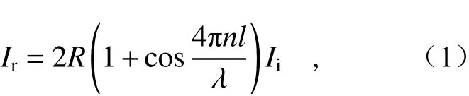
whereRis the reflectivity of the end face of the fiber-optic FP cavity,nis the refractive index of the cavity of the fiber sensor,lis the length of the FP cavity, λ is the wavelength of the light wave, andIiis the intensity of the light entering the demodulation system.
The light source used in the non-scanning correlation demodulation method is a broadband light source. When calculating the total light intensity of the correlation interference signals, the light intensity values of the correlation interference signals generated by all wavelengths should be added to obtain the total light intensity of the signals output through the fiber-optic FP sensor and optical wedge, as shown:whereR1represents the reflectivity of the wedge surface, θ represents the wedge angle, andxrepresents any position on the long side of the right triangle.
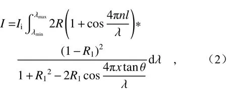
The analysis of the correlation interference signals in Equation (2) shows that, in the non-scanning correlation demodulation method, when the maximum correlation signal is observed, the wedge thickness corresponds to the cavity length of the fiber-optic FP sensor, namelyxtanθ=l. This phenomenon is called cavity length matching. Thus, the cavity length of the fiber-optic FP sensor can be demodulated.
3 Characterization of demodulation devices
3.1 Light source
In practical applications, the spectral distribution of a light source is not completely uniform. In order to analyze the influence of different spectral distributions on the demodulation signal, three spectral distribution curves with different shapes,namely Gaussian shape, triangle and rectangle, were chosen in this paper, as shown in Figure 3 (Color online). Among them, the Gaussian and triangular spectra were used to simulate the spectrum of SLED light source, while the rectangular spectrum was used to simulate the spectrum of erbium-doped fiber laser source. The 3 dB bandwidths and central wavelengths of the three light sources were all the same. Since the spectral response range of linear array CCD was 400 nm−1100 nm, the central wavelengths of the three spectral curves were assumed to be 850 nm. As can be seen from the figure, when the spectral curves of the three broadband light sources have the same 3 dB bandwidth, the effective spectral width of the Gaussian light source is the largest, while that of the rectangular light source is the smallest.
Considering the spectral distribution characteristics of the light source and the spectral distribution characteristics of the light traveling in space,the mathematical model of correlation interference signals can be obtained according to equation (2):
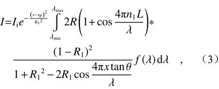
wherexpis the position of the central wavelength,xis the length of the distance fromxp,Bxis the FWHM of the Gaussian distribution function of the light traveling in space, andf(λ) is the mathematical model of the spectral distribution of different light sources.
To obtain the spectral distribution curves of the three light sources, the central wavelength of the simulated light source was assumed to be 850 nm,the 3 dB bandwidth was 60 nm, the length of the fiber-optic FP cavity was 80 μm, the thickness of the optical wedge was between 50 μm and 100 μm,and the length of the optical wedge was 0.03 m.Through simulation, the intensity distribution curves of the optical wedge were obtained under the spectral distributions of different light sources (Fig. 4).
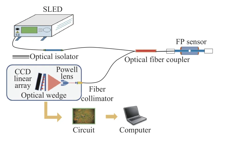
Fig. 1 Schematic diagram of optical wedge demodulation system for fiber-optic FP sensor图 1 光纤法珀传感器光楔式解调系统示意图
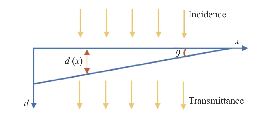
Fig. 2 Schematic diagram of optical wedge structure图 2 光楔结构示意图
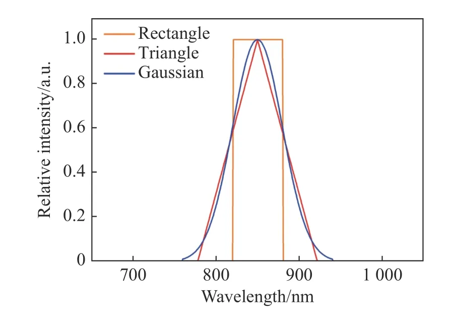
Fig. 3 Three kinds of spectral distribution curves图 3 3种光谱分布曲线
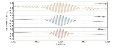
Fig. 4 The output light intensity distribution of correlation interference signal under different spectral distributions图 4 不同光谱分布下相关干涉信号输出分布
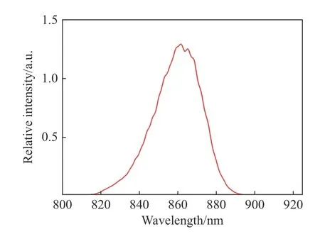
Fig. 5 Output spectrum of SLED图 5 SLED输出光谱
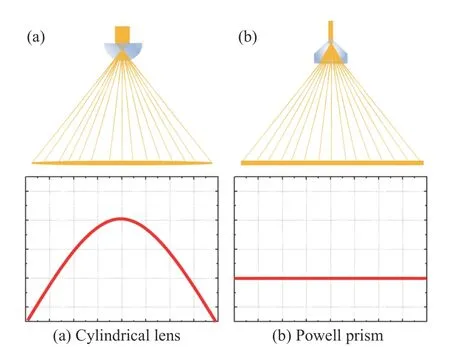
Fig. 6 Light intensity distributions of (a) cylindrical lens and (b) Powell prism图 6 (a)柱透镜和(b)鲍威尔棱镜光强分布效果图
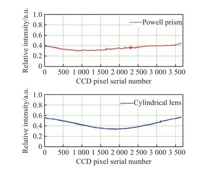
Fig. 7 Light intensity distributions of the background signals from cylindrical lens and Powell prism detected by CCD图 7 柱透镜和鲍威尔棱镜光强分布经CCD探测基底信号图

Fig. 8 Comparison of correlation interference signals obtained by the optical wedges with different surface reflectivities图 8 不同表面反射率的光楔的相关干涉信号对比图

Fig. 9 Optical wedge structure of fiber-optic FP sensor demodulation system. (a) Schematic diagram of optical wedge fabrication; (b) combination of CCD and optical wedge图 9 光纤法珀传感器解调系统的光楔结构。(a)光楔制作示意图;(b)CCD结合光楔实物图

Fig. 10 Schematic diagram of fiber-optic FP sensor图 10 光纤法珀传感器示意图
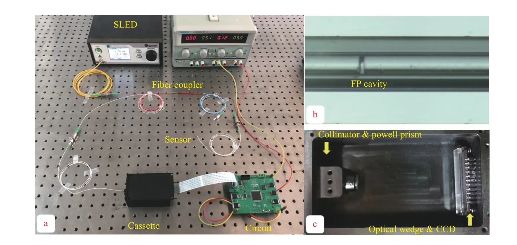
Fig. 11 Experimental optical wedge demodulation system for the fiber-optic FP sensor. (a) Overall structure; (b) detailed picture of the sensor; (c) internal structure of dark box图 11 光纤法珀传感器光楔式解调实验系统。(a) 整体结构 (b) 传感器细节图 (c) 暗盒内部结构
It can be seen from the comparison that, when the 3 dB bandwidths and spectral ranges of all the spectra are the same, the curve of the light intensity distribution under the action of Gaussian spectrum has less background signal noise and higher output signal contrast than those of triangular and rectangular spectra to facilitate accurate peak-finding and high-precision demodulation. Influenced by the characteristics of Gaussian spectrum itself, the integral spectral range of Gaussian spectrum is larger than that of triangular or rectangular spectrum.However, when the spectral range is larger, different groups of correlation interference fringes are superimposed on each other, leading to more sparse correlation interference signal fringes, higher fringe contrast and greater light intensity. In addition, the wide-spectrum light source has a suppression effect on the noise, mainly because it has a small coherence, which reduces the coherence error introduced by the noise. According to the analysis, a SLED with a 3 dB bandwidth of 60 nm was selected as the broadband light source, whose spectrum was shown in Figure 5.
3.2 Powell lens
In the optical wedge non-scanning correlation demodulation method, the correlation module is generally the combination of a large-aperture fiber collimator, a cylindrical lens, an optical wedge and a CCD. The light passes through the fiber collimator to the cylindrical lens. The cylindrical lens converts the light into linear beams, which, in turn, shine on the optical wedge. Then the wedge outputs the correlation interference signals. The CCD collects the optical signals and converts them into electrical signals. For the correlation module of this structure, it was found in the experiment that for the lens reason,the DC bias distribution of the obtained correlation interference signals was not uniform, which affected the demodulation of the cavity length. Therefore, the fiber collimator and the cylindrical lens were optimized. The size of the fiber collimator was reduced and the cylindrical lens was changed into a Powell prism, so as to greatly reduce the system size and eliminate the influence of non-uniform bias distribution.
Different from cylindrical lens, Powell prism can convert the light very well, so that the light is distributed evenly within the fan angle of Powell prism, rather than more in the middle and less at the edge in a cylindrical lens. The light intensity distributions of the cylindrical lens and Powell prism are shown in Figure 6. The beam distribution formed after the light passes through the cylindrical lens is shown in Figure 6(a). It can be found that, the light intensity is mainly concentrated in the middle and decreases with the distance from the center, as seen in the Gaussian distribution. The beam distribution formed after the light passes through the Powell prism is shown in Figure 6(b). After passing through the Powell prism, the light energy is evenly distributed within the fan angle. This distribution effectively eliminates the defect that the light intensity is stronger in the middle and weaker at the edge.
In an experiment, the combination of a largeaperture collimator and a cylindrical lens was compared with the combination of a small-aperture collimator and a Powell prism, and a linear array CCD was used to detect the two groups of signals. The results are shown in Figure 7, where the abscissa represents the CCD pixel serial number and the ordinate represents the relative intensity. The results show that the background signal distribution obtained by Powell prism is more uniform than that obtained by cylindrical lens, so the use of Powell prism as the beam-shaping structure is more beneficial to signal demodulation.
3.3 Optical wedge
Optical wedge is the key device to realize the demodulation in the system. It directly determines whether the correlation operation can be implemented. Therefore, optical wedge is very important for the whole demodulation system. The design and selection of optical wedge need to consider the cavity length range of the sensor. The initial cavity length of the fiber-optic FP sensor used in the experiment was about 80 μm. In order to expand the measurement range as much as possible, the wedge thickness range was roughly set as 50 μm−100 μm. According to Equation (2), the reflection coefficient of the wedge can affect the light intensity of the correlation interference signal. In order to better determine this relationship, the light intensity distribution of the correlation interference signal was simulated when the reflection coefficientRwas 0.1, 0.3, 0.5,0.7 and 0.9.
The simulation results are shown in Figure 8(Color online). As can be seen from the figure, the light intensity of the correlation interference signal decreases gradually with the increase of the reflectivityR, and the contrast of the correlation interference signal reaches its maximum atR=0.5.Therefore, it was determined that the outer surface of the wedge should be coated with an antireflection film covering the entire spectral range, while the inner surface should be coated with a semi-reflection semi-transmission film covering the entire spectral range.
The wedge width should be consistent with the CCD width. Two glass sheets were used to fabricate the optical wedge. At first, two clean glass sheets of suitable length were chosen, with one side coated with an anti-reflection film and the other side coated with a semi-reflection semi-transmission film. Two film shims, 50 μm and 100 μm thick respectively, were prepared. Then the semi-reflection semi-transmission surfaces of the two glass sheets leaned against each other. The 50-μm thick shim was sandwiched at one end between the glass sheets and the 100-μm thick shim at the other end. Finally,an optical wedge was formed by bonding the ends of the two glass sheets with ultraviolet glue. Then,the finished optical wedge was pasted on the CCD with ultraviolet glue, as shown in Figure 9.
4 Experimental verification
Non-intrinsic fiber-optic FP sensor is typically fabricated by inserting single-mode fibers into a hollow glass tube (Figure 10). At first, two segments of single-mode fibers with flat ends and one segment of hollow glass tube are prepared. Then the two fibers are inserted into the glass tube from both ends to form a FP cavity in tube with air as the medium.Usually, the joints between the glass tube and the fibers are fixed with UV glue in order to obtain a stable cavity structure. Alternatively, the fiber sections can be coated with film to improve the reflectivity and form a non-intrinsic fiber-optic FP sensor with high fineness.
The non-scanning correlation demodulation system for fiber-optic FP sensor was built, as shown in Figure 11. The system was composed of a SLED
light source with the central wavelength of 850 nm and the 3 dB bandwidth of 60 nm, a 2×1 fiber coupler, a fiber-optic FP sensor, a fiber collimator, a 30-mm long Powell prism, an optical wedge (50 μm−100 μm thick), a linear array CCD and a data processing unit. Among them, the fiber collimator, the Powell prism, the optical wedge and the CCD were fixed in a dark box.
An fiber-optic FP sensor with an initial cavity length of 80.067 μm was connected to the established experimental platform. The correlation interference signals were converted by CCD into electrical signals for data processing. The curve of the collected correlation interference signal is shown in Fig. 12 (Color online). The abscissa represents the pixel point position, and the ordinate represents the relative intensity of the correlation interference signal converted into a digital signal.
As can be seen from the blue curve in Fig. 12,the acquired signal contains not only the useful signal, but also low-frequency bias and high-frequency noise. At first, the signal was converted to the frequency domain through Fourier transform. The frequency band where the signal was located was determined. Then, inverse Fourier transform was applied to the signal in this frequency band to achieve bandpass filtering. The red curve in the figure represents the signal obtained by the bandpass filter. It can be seen that compared with the original signal,the high-frequency noise and low-frequency bias in the filtered signal have been removed, and the curve has become smooth with an obvious envelope.Then, direct peak-searching calculation can be made. Alternatively, the envelope curve of the filtered signal can be fitted and finally, the maximum peak position on the fitted envelope curve can be found. The calculation result shows that, the maximum value of the correlation interference signal generated by the fiber-optic FP sensor with an initial cavity length of 80.067 μm is at the pixel point position 1729.739.
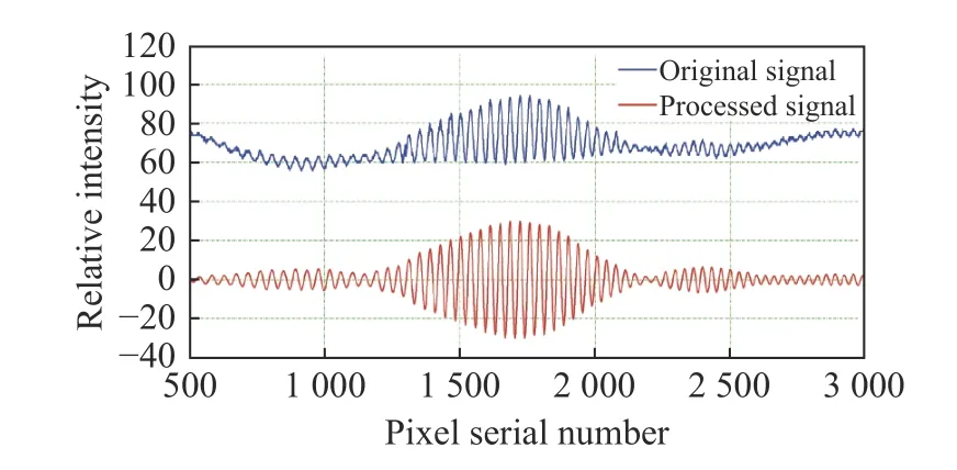
Fig. 12 Signals collected by CCD in the optical wedge demodulation system for fiber-optic FP sensor图 12 光纤法珀传感器光楔式解调系统CCD采集信号图
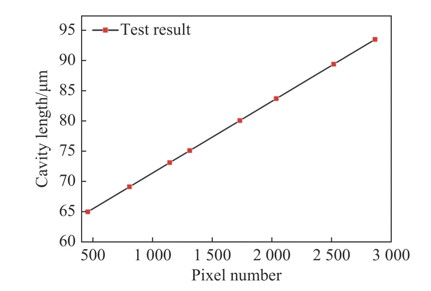
Fig. 13 Test results of optical wedge demodulation system for fiber-optic FP sensor图 13 光纤法珀传感器光楔式解调系统测试结果图
By calibrating the demodulation system and the standard fiber-optic FP sensor, the correspondence relation between the pixel point position at the peak value of the correlation interference signal and the cavity length is obtained asL=11.889·n+59 511.072 nm, whereLis the cavity length of the FP sensor,nis the pixel serial number corresponding to the peak position of the correlation interference signal, and the fitting coefficient isR2=0.999 9. 8 fiber-optic FP sensors with the cavity lengths of 65.002 μm, 69.141 μm, 73.125 μm,75.109 μm, 80.067 μm, 83.692 μm, 89.388 μm and 93.474 μm respectively were connected to the demodulation system one by one. The measured and fitting results are shown in Figure 13. It can be seen that the maximum error is 9 nm and the fullscale measurement error is less than 0.025%.
Under different light source power, the demodulation ranges of the optical wedge demodulation systems using Powell prism and cylindrical lens were compared, as shown in Fig. 14, and the corresponding data is also given in Table 1. It can be seen that the demodulation system using Powell prism has strong light source stability, small demodulation range fluctuation and relatively stable performance. When the power of the light source is less than 6 mW, the demodulation system using cylindrical lens cannot realize demodulation because of the disappearance of the correlation interference signal.This further demonstrates the advantage of Powell prism in the adaptability to light source power.
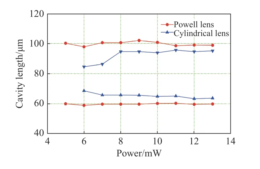
Fig. 14 Comparison of demodulation ranges of the demodulation systems using Powell prism and cylindrical lens under different light source powers图 14 不同光源功率下采用鲍威尔棱镜及柱透镜的解调系统的解调范围对比图
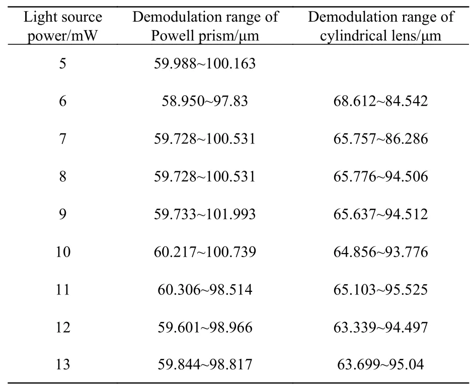
Tab. 1 Test data表 1 测试数据
5 Conclusion
In this paper, a non-scanning correlation demodulation method based on optical wedge was proposed for the demodulation of fiber-optic FP sensor, and the demodulation system was optimized.The simulation analysis of light source and optical wedge found that, when the light source spectrum was Gaussian distribution, the bandwidth was large and the surface reflectivity of optical wedge was R=0.5, the correlation interference signal of the demodulation system could achieve a higher contrast,which was convenient for accurate peak searching and demodulation. In addition, by applying the Powell prism, the influence of light intensity was greatly improved in a certain range of light power,and the adaptability of this modulation system to the light source power was enhanced. Through the calibration of this system, the final measurement range error was reduced to less than 0.025%.
中文对照版
1 引 言
光纤法布里-珀罗(法珀)传感器作为光纤传感的重要成果,得到了快速发展,其具有精度高、体积小、抗干扰等特点,广泛应用在航空航天、土木工程、医疗等领域[1-3]。由于外界物理量的变化会影响法珀传感器的腔长,故可以通过解调腔长信息,实现对于压力、温度、应变等不同物理量的测量[4-5]。
光纤法珀传感器可分为本征型和非本征型,本征型结构的光纤法珀传感器属于内腔式结构,其腔体由光纤构成,利用光纤可以传感的特征感知外界信息的变化。而非本征型是一种外腔式结构,腔体一般是空气或真空,腔体的形成多采用空芯光纤、毛细管或弹性膜片等敏感元件,用于感知物理量的变化,光纤仅仅起到传输信号的作用[6-7]。……
登录APP查看全文
猜你喜欢
工业设计(2022年8期)2022-09-09 07:43:20
鸭绿江(2021年35期)2021-04-19 12:24:18
军民两用技术与产品(2021年10期)2021-03-16 06:05:30
北京测绘(2020年12期)2020-12-29 01:33:58
考试与评价·高一版(2020年6期)2020-11-02 02:45:24
装备制造技术(2019年12期)2019-12-25 03:06:46
中国洗涤用品工业(2019年4期)2019-05-11 09:27:34
中国生殖健康(2019年3期)2019-02-01 06:12:26
家庭影院技术(2017年9期)2017-09-26 03:41:45
凿岩机械气动工具(2016年3期)2016-03-01 04:00:25
- 中国光学的其它文章
- Surface plasmon resonance characteristics of a graphene nano-disk based on three-dimensional boundary element method
- A new automatic cell smear and laser release system for near-infrared light responsive release of nucleated red blood cells
- Photon-assisted Fano resonance tunneling periodic double-well potential characteristics
- Formation mechanism of the continuous spectral profile of lightning plasma
- 中国遥感卫星辐射校正场敦煌戈壁场区光环境变化研究
- 油气井下光纤光栅温度压力传感器