
Ideal optomechanically induced transparency generation in a cavity optoelectromechanical system∗
2021-10-28 07:01JingWang王婧andXueDongTian田雪冬
Chinese Physics B 2021年10期
Jing Wang(王婧) and Xue-Dong Tian(田雪冬)
1College of Physics,Tonghua Normal University,Tonghua 134000,China
2College of Physics Science and Technology,Guangxi Normal University,Guilin 541004,China
Keywords: ideal optomechanically induced transparency,cavity optoelectromechanical system,transparency window width
1. Introduction
Cavity optomechanical systems[1–38]have become one hot topic in the development of manipulating light. During the past decades, scientists have never stopped exploring,then a series of phenomena have been obtained one after the other in cavity optomechanical systems,for example,optomechanically induced transparency(OMIT),[4,5]entanglement,[8]ground-state cooling of the mechanical resonator,[9–11]optomechanically induced absorption,[7,12]amplification,[13]normal-mode splitting,[14]and Fano resonance.[15]A notable achievement discovered among these phenomena is OMIT,which has been first proposed theoretically in Ref. [4] and first experimental demonstrated in Ref. [5]. Subsequently,many significant new phenomena have been achieved base on OMIT,such as reversed OMIT,[17,18]nonlinear OMIT,[19]vector OMIT,[20]multiple OMIT,[15,21]higher-order OMIT,[22]and nonreciprocal OMIT.[23]These phenomena make cavity optomechanical system a powerful platform to realize light storage and delay[24,25]on account of the abnormal dispersion accompanied with a small width of the transparency window.[1,2]However, a practical problem is that it is very difficult to achieve both a large depth and narrow width of the transparency window in OMIT.[1,2]So, it is still a longstanding challenge to obviously improve OMIT. But recently Yan[1,2]studied ideal OMIT with the non-rotating wave approximation(NRWA)effect which was not considered in previous works. Compared with the traditional OMIT case, in which there still exists little residual absorption at the window centre, the idea OMIT means precise non-absorption indicating the unitary window depth at the window center. In addition,the width of the window is also narrow,so it is viable to achieve ideal transparency and the ultraslow light.
The conventional cavity optomechanical systems can be made up of one optical cavity,and one mechanical resonator.Most attention has been focused on the conventional cavity optomechanical system, but it is necessary to generalize it to different complex cavity optomechanical systems,[39–46]because that complex cavity optomechanical systems can exhibit more richer quantum behaviors. Complex cavity optomechanical systems include multi-mechanical resonator cavity optomechanical system,[39]cavity optoelectromechanical system,[40,42]atomic-medium assisted cavity optomechanical system,[16]multi-cavity optomechanical system with and without optical parametric amplifier,[44–46]and so on. In the complex cavity optomechanical systems, cavity optoelectromechanical system has attracted more attention, which is composed of a charged object and a cavity optomechanical system. In this system, Zhanget al.[42]has implemented the precise measurement of the charge number for small charged object via OMIT.
Although Zhanget al.[42]have proposed the scheme to realize precise measurement in cavity optoelectromechanical system,other output probe field properties of this system also attract our interest. In this work, inspired by the ideas in Refs.[1,2,42],we consider to explore the ideal OMIT properties in a cavity optoelectromechanical system with the NRWA effect. To our knowledge, the ideal OMIT considering the NRWA effect has not been studied in a cavity optoelectromechanical system. Our work shows the ideal OMIT can be achieved via NRWA effect. With the appropriate parameter regime, we further consider the effect of the interaction between a charged mechanical resonator and a charged object with coulomb coupling strength, the cavity decay rate, and mechanical resonator damping rate on the ideal OMIT phenomenon. Firstly,the ideal OMIT phenomenon can be found in the resolved or unresolved sideband regime, respectively.Secondly,by increasing coulomb coupling strength,the location of the OMIT dip moves leftward significantly. Thirdly,the transparency window width of ideal OMIT is sensitive to the cavity decay rate, which is very important because cavity decay rate increases,transparency window width becomes narrower and does not affect the depth of the window. Fourthly,the maximum dispersion curve slope also depends on the cavity decay rate.
2. Model and equations
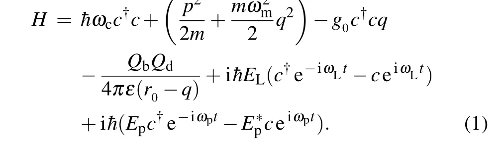
The cavity optoelectromechanical system considered in our work is presented schematically in Fig. 1, and the optical cavity is driven by a relatively strong driven field (frequencyωL, strengthEL) and a weak probe field (frequencyωp, strengthEp). The charged mechanical resonatorQb(frequencyωm,massm,damping rateγm,positionq,momentump, and chargeQb) is simultaneously coupled to the optical cavity(frequencyωc)via radiation pressure and to the adjoining charged objectQd(chargeQd)via the Coulomb force. So,there are two kinds of interaction in the cavity optoelectromechanical system,which include optomechanical coupling and the Coulomb interaction. In the absence of optomechanical coupling and the Coulomb interaction, the equilibrium separation from the charged object to the charged mechanical resonator is expressed byr0. The Hamiltonian of the cavity optoelectromechanical system is given as[42]


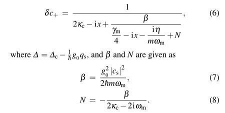
From Eq. (6), we notice that the termNis very interesting. When we apply rotating wave approximation to solve the Langevin equations,the termNdoes not exist inδc+(see Appendix A for details). Hence we call the termNis NRWA effect.[1,2]
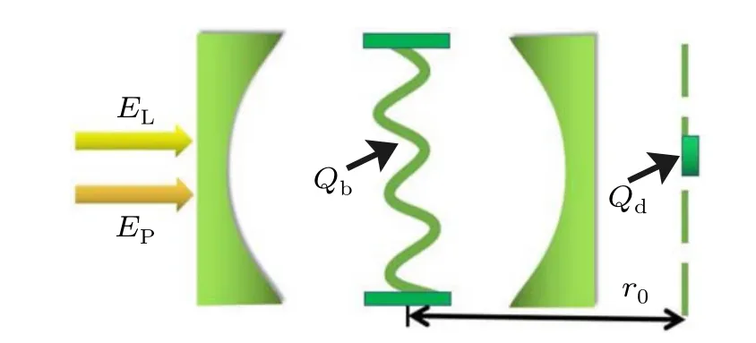
Fig.1.Schematic diagram for the cavity optoelectromechanical system with one optical cavity,one charged mechanical resonator charges is Qb,and one charged object charges is Qd. The charged mechanical resonator is coupling to an adjoining charged object via the Coulomb force. The strong drive field with amplitude EL and weak probe field with amplitude Ep are applied to drive the optical cavity. In the absence of the radiation pressure and the Coulomb force,the equilibrium separation between the charged object and the charged mechanical resonator is expressed by r0.[42]
According to the theory of the input-output relation,εT=2κδc+, the component of the output field at the probe frequency is given as

The real part Re[εT]shows the absorption of output probe field,and the imaginary part Im[εT]shows the dispersion of output probe field. According to Refs.[1,2],ifN=0,the absorption line of the output probe field presents OMIT.With the termN,the conditions of the ideal OMIT dip can be easily obtained.Next, we will discuss the condition of ideal OMIT according to Eq.(9).
3. Results and discussion
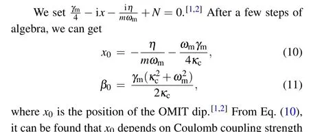


Fig.2. The real part Re[εT]((a)and(c))and imaginary part Im[εT]((b)and(d))of the output probe field as a function of normalized frequency detuning x/γm in resolved sideband regime κc=0.2ωm ((a)and(b))and unresolved sideband regime κc=2ωm ((c)and(d)).
Equation(10)shows that the Coulomb coupling strengthηis the parameter that could affect the position of the ideal OMIT dipx0. Therefore,how to modulate Coulomb coupling strengthηbecomes a issue. We consider the effects of theηon the ideal OMIT in the case of the resolved sideband regimeκc<ωm. In Fig. 3(a), we plot the real part Re[εT] of the output probe field versus the normalized frequency detuningx/γmfor the Coulomb coupling strengthηin the case of resolved sidebandκc<ωm. The Coulomb coupling strengthηis set with different values:η=η0(red solid curve),η=8η0(blue dashed curve),andη=100η0(black dotted curve)withη0=50 Hz. From the red solid curve,blue dashed curve and black dotted curve in Fig.3(a),we can see that with different coupling strengthη, the OMIT dip appears in different position. In the case of Coulomb couplingη=η0(red solid cure),we can getx0/γm=2.25,which is coincide with Fig.2(a). As for the black dotted curve,we set Coulomb coupling strengthη=100η0,and compared with blue dashed curve,we find the location of the ideal OMIT dip changes more obviously. So,it can be clearly seen that the dip of the ideal OMIT moves leftward with the Coulomb coupling strengthηincreasing. From Eq. (10), we know that ifκc/ωmis fixed, the location of the ideal OMIT dipx0/γmdecreases monotonically with Coulomb coupling strengthηincreasing. In Fig.3(b),we plot the location of the ideal OMIT dipx0/γmversus the Coulomb coupling strengthη/η0. The trend reflected in Fig. 3(b) indicates that the value ofx0/γmwill definitely become smaller with increase of Coulomb coupling strengthη.
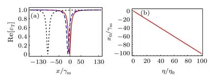
Fig.3. (a)Real part Re[εT]of the output probe field versus the normalized frequency detuning x/γm for different values of η in the cases of resolved sideband regime κc<ωm. Here η=η0 for the red solid curve,η=8η0 for the blue dashed curve,and η=100η0 for the black dotted curve.(b)The location of the OMIT dip x0/γm versus the Coulomb coupling strength η/η0.We assume that κc is a fixed value κc=0.2ωm,η0=50 Hz.
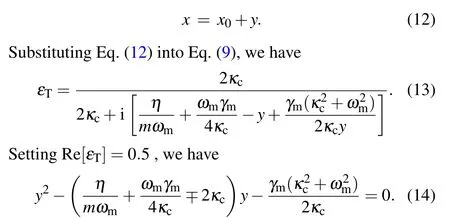
In the following,we can obtain the transparency window widthΓ(full width at half maximum)from Eq.(9). To obtain the transparency window widthΓ,we thus need to specify[1,2]
Equation (14) is a quadratic equation inythat will have two distinct rootsy1andy2,
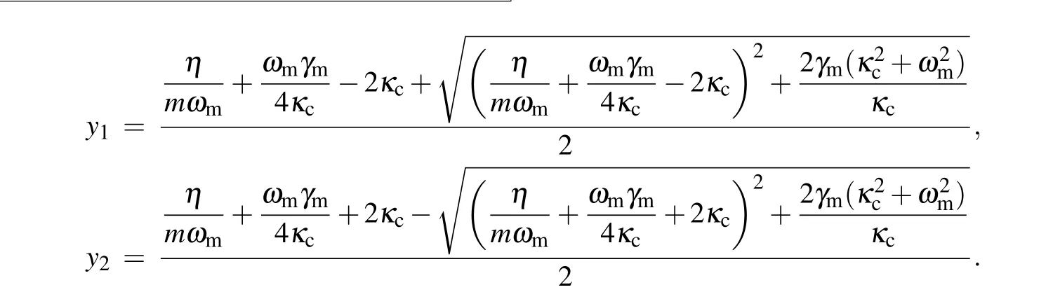
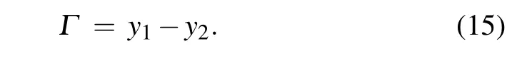
Then the transparency window width can be calculated by the difference between the two roots[1,2]
In order to get deeper insight into the transparency window width, we need to deal with Eq. (15). It is shown that under certain conditions(γm≪ωm,κc),the complicated expression of Eq.(15)can be simplified as
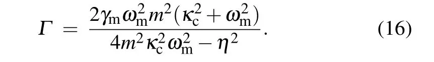
In Eq.(16),the transparency window widthΓwill change with differentγm,andκc.To see the effect of the optical cavity decay rateκc/ωmand charged mechanical resonator damping rateγmon the transparency window width, we plot the transparency window widthΓas functions of the decay rate of cavityκc/ωmand charged mechanical resonator damping rateγmin Fig.4(a)with unresolved sideband regimeκc>ωmand in Fig. 4(b) with the resolved sideband regimeκc<ωm.Figures 4(a) and 4(b) show that the trend of the transparency window widthΓagrees very well for this two cases. We can obtain the following three results,the first one of which is that the larger charged mechanical resonator damping rateγmwill induce wider transparency window, ifκc/ωmis fixed. Secondly, when mechanical resonator damping rateγmis fixed,largerκcleads to the decrease of the transparency window widthΓ, so the transparency window becomes narrower and sharper. Thirdly, we see that the transparency window widthΓincreases significantly whenκcincreases from unresolved sideband regime to resolved sideband regime. For example,we can see that the transparency window width reaches the valueΓ= 125 Hz whenκc/ωm= 0.2 and mechanical resonator damping rateγm=10 Hz for fixedη=50 Hz. However, under the same conditions, exceptκc/ωm= 1.5, the transparency window width reaches to the value ofΓ=10 Hz.We need to emphasize that although the transparency window becomes narrower and sharper with largerκc,the depth of the transparency windows remain unchanged.
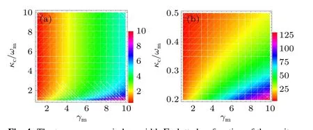
Fig.4. The transparency window width Γ plotted as function of the cavity decay rate κc/ωm and charged mechanical resonator damping γm. (a) The unresolved sideband regime κc > ωm and (b) resolved sideband regime κc<ωm.
Besides of the manipulation of Re[εT] byκc, Im[εT]can also be affected byκc. From Eq. (13), we can get Im[εT] and further calculate the dispersion curve slopeK=∂Im[εT]/∂y,[1,2]so we obtain the following equation:
It can be seen that the form of Eq. (17) is somewhat complicated. According to Eq.(17),the maximum dispersion curve slope is given by

withy=0. In Eq. (18),κcandγmplay important roles. In addition,Kmaxis immune to Coulomb coupling strengthη.
We want to investigate the effect ofκconKmax. So, we plotKmaxvaries versusκc/ωm,withγm=1 Hz(red solid line),γm=0.7 Hz(blue dashed line),andγm=0.4 Hz(black dotted curve), in Fig. 5. As depicted clearly in Fig. 5, with the increase ofκc/ωm,the dispersion curve slopeKmaxreduces significantly at first, which means that the narrow transparency dip deepens. That is to say,the ideal OMIT effect is enhanced,however, while further strengtheningκc/ωm, the maximum dispersion curve slopeKmaxstarts to be stable. Meanwhile,the curve withγm=1 Hz(red solid line)is much steeper than that withγm=0.7 Hz(blue dashed line).The steeper the slope of dispersion curve is,the more significant the slow light effect becomes.

Fig.5.The dispersion curve slope Kmax as a function of the charged mechanical resonator damping κc/ωm,with γm=1 Hz(red solid line),γm=0.7 Hz(blue dashed line),and γm=0.4 Hz(black dotted curve).
4. Conclusions
The aim of the present work is to investigate the ideal OMIT properties in a cavity optoelectromechanical system driven by strong pump field and weak probe field.The charged mechanical resonator is simultaneously coupled to the optical cavity via radiation pressure and to the adjoining charged object via the Coulomb force. Solving the quantum Langevin equations for the cavity optoelectromechanical system operators and using the input-output relation of the cavity,we derive an analytical expression for the output probe field. Although the charged mechanical resonator damping rate is nonzero,the ideal OMIT can still appear when we apply the non-rotating wave approximation effect. In addition,we analyze the effects of the Coulomb coupling strength, optical cavity decay rate,and charged mechanical resonator damping rate on the ideal OMIT.
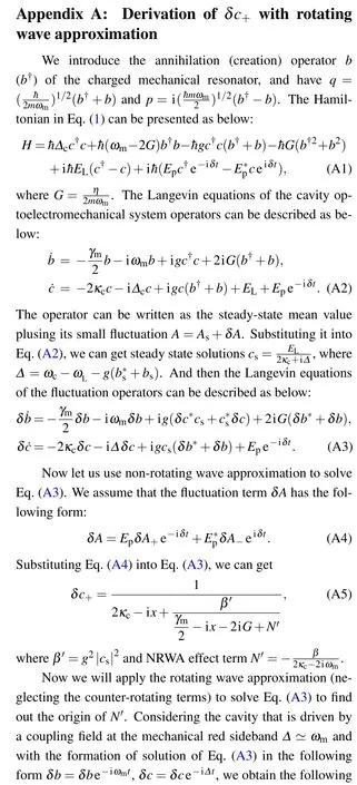
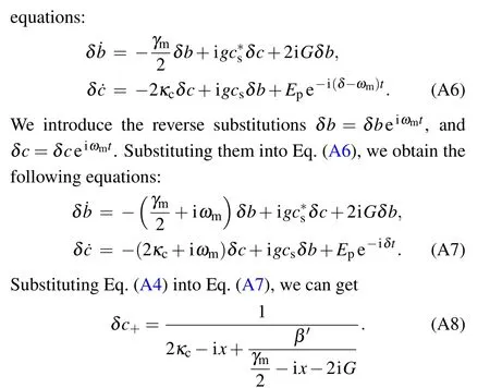
The termN′does not appear in Eq. (A8). It is clear that the origin of the termN′in Eq.(A5)is the NRWA effect.

- Chinese Physics B的其它文章
- Physical properties of relativistic electron beam during long-range propagation in space plasma environment∗
- High winding number of topological phase in non-unitary periodic quantum walk∗
- Widely tunable single-photon source with high spectral-purity from telecom wavelength to mid-infrared wavelength based on MgO:PPLN∗
- Control of firing activities in thermosensitive neuron by activating excitatory autapse∗
- Adaptive synchronization of chaotic systems with less measurement and actuation∗
- Dynamics analysis of a 5-dimensional hyperchaotic system with conservative flows under perturbation∗