
Effects of Microstructure on Quasi-Static Transverse Loading Behavior of 3D Circular Braided Composite Tubes
2021-11-02 03:12ZHOUHaili周海丽LIChaoHANChenchen韩晨晨LIUZhiyan刘志艳ZHOUFengZHANGLiquan张立泉
ZHOU Haili(周海丽), LI Chao(李 超), HAN Chenchen(韩晨晨), LIU Zhiyan(刘志艳), ZHOU Feng(周 峰), ZHANG Liquan(张立泉)
Nanjing Fiberglass Research & Design Institute, Nanjing 210000, China
Abstract: The effects of microstructure on quasi-static transverse loading behavior of 3D circular braided composite tubes were studied. Transverse loading tests were conducted. Transverse load-deflection curves were obtained to analyze the effects of braiding parameters including the braiding angle, the wall thickness, and the diameter on the transverse loading of 3D circular braided composite tubes. Breaking loads, moduli and strengths had also been used to describe the transverse loading behaviors. The failure morphologies were shown to reveal damage mechanisms. From the results, the increase in braiding angle, wall thickness and diameter increases the ability of anti-deformation and breaking load of braided tubes. The breaking load of specimen with a braiding angle of 45° is about 1.68 times that of specimen with a braiding angle of 15°. The breaking load of specimen with 4 layers of yarns is about 2.15 times that of specimen with 2 layers of yarns. The breaking load of the tube with a diameter of 25.5 mm is about 2.39 times that of the tube with a diameter of 20.5 mm.
Key words: 3D circular braided composite tube; quasi-static transverse loading test; braiding parameter; failure morphology
Introduction
3D braided preform as one of textile reinforcement for composites is increasingly used in aircraft, ships, vehicles and civil engineering. 3D braided composite has superior structural integrity which overcomes the delamination through the thickness of laminated composite. Tube is a very common structure in engineering fields subjected to different loads such as axial load, transverse load and shear. Many scholars have investigated mechanical properties of circular braided composite tubes. The tensile properties[1-3]and the axial crush properties[4-9]of braided composite tubes have been studied both experimentally and theoretically. Karbhari and Haller[5]investigated the effects of rate and architecture on the progressive crush of the 3D braided tube. As a result, the increase in size of axial tow resulted in an increase in peak load. Karbhari[6]still studied the effect of lateral impact simulating prior damage on the progressive crush characteristics of 2D braided composite tubes by hybridization. Chiuetal.[7]investigated the effects of braiding angles and the axial yarn content on the crush failure characteristics under quasi-static axial compression. The results showed that the main failure mode was splaying, and the average width of the splaying fronds increased with the increase of braiding angle, but decreased with the increase of axial yarn content.
Several studies have been done on transverse loading of tubes. Kimetal.[10]studied quasi-static transverse loading behavior of carbon fiber reinforced polymer(CFRP) tubes combined with aluminum. They found that the tube structure affected the energy absorption. Liuetal.[11]studied quasi-static transverse loading and axial crushing of CFRP tubes and found that the abilities to bear load and absorb energy for the tubes under transverse loading were much lower than those under axial compression. Potlurietal.[12]presented flexural and torsional properties of biaxial and triaxial braided composites with different braiding parameters. From the results, triaxial braids had higher bending stiffness than biaxial braids and 2-layer braids had about 2.5 times bending stiffness of single-layer braids. Jinetal.[13]studied the effect of braiding angle on low-velocity transverse punch response of braided composite tubes. The results showed that the initial bending stiffness of the tube increased with the increase of the braiding angle. However, most tubes studied under transverse loading were laminates and 2D braided tubes. For this reason, more studies need to be concentrated on 3D circular braided composite tubes. Some authors[14-18]of this paper have studied the effect of microstructure on transverse and axial impact behaviors of 3D braided composite tubes at a high speed.
This paper investigates the effects of braiding parameters on the quasi-static transverse loading behavior of 3D circular braided composite tubes. The failure morphologies are given to further understand the damage mechanism of 3D braided composite tubes under quasi-static transverse loading.
1 Material and Testing Methods
1.1 3D circular braided composite tube
Three groups of four-step 3D braided tube preforms with different outer braiding angles were manufactured: 15°, 30° and 45°. Composite tubes with different layers of yarns and different inner diameters of 20.5 mm and 25.5 mm were also manufactured. The preforms were manufactured from carbon fiber tows(Japan Toray®, T700-12k, 800 tex, 1.80 g/cm3).
Vacuum assisted resin transfer molding(VARTM) process was used to impregnate the tube preforms. Curing was done with the following conditions: 90 ℃ for 2 h, 110 ℃ for 1 h and finally 130 ℃ for 4 h. The specimens and the cross-sections are shown in Figs. 1 and 2. The average sizes and fiber volume fractions of the 3D braided composite tubes are listed in Table 1, respectively. It is clear that the wall thickness increases with the increasing braiding angles and the increasing number of braiding layers.

Table 1 Geometric parameters of samples
1.2 Quasi-static transverse loading tests
Quasi-static transverse loading test of 3D circular braided composite tubes was carried out on a material testing system(MTS) 810.23® material tester made in Minnesota, USA as shown in Fig. 3. Three groups of repeated tests were performed for each type of the test specimen. Samples were placed on two support arcs with a span of 100 mm. The semicircle arc head was loaded at a constant speed of 5 mm/min. Two metal plugs were inserted into both ends of the tube to avoid section deformation,i.e., flattening. Transverse load-deflection curves were obtained until failure of the sample. The equations for transverse strengthσand transverse modulusEof the specimen can be expressed by
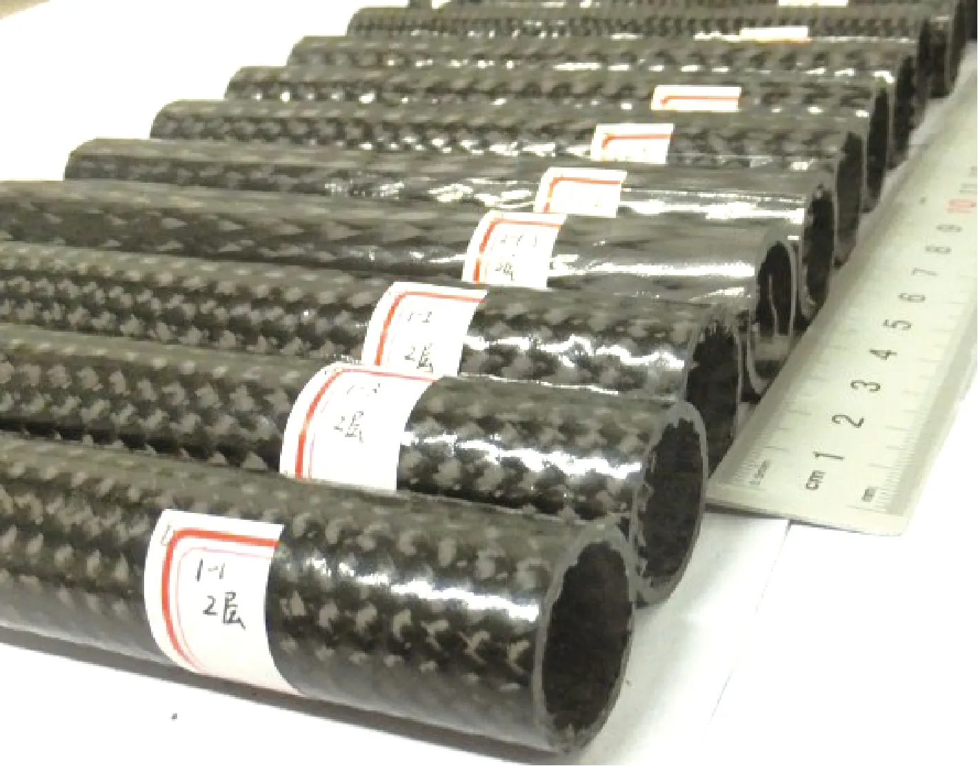
Fig. 1 Tube samples
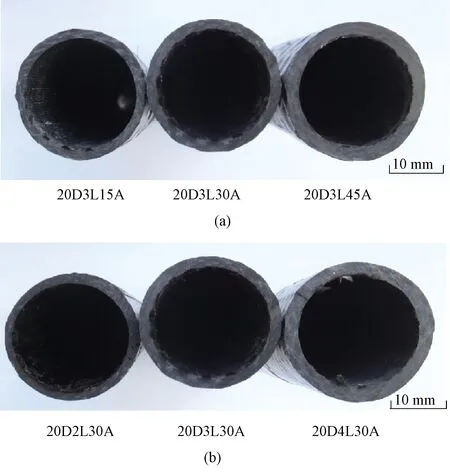
Fig. 2 Cross-sections of tubes: (a) tubes with different braiding angles; (b)tubes with different braiding layers; (c)tubes with different diameters
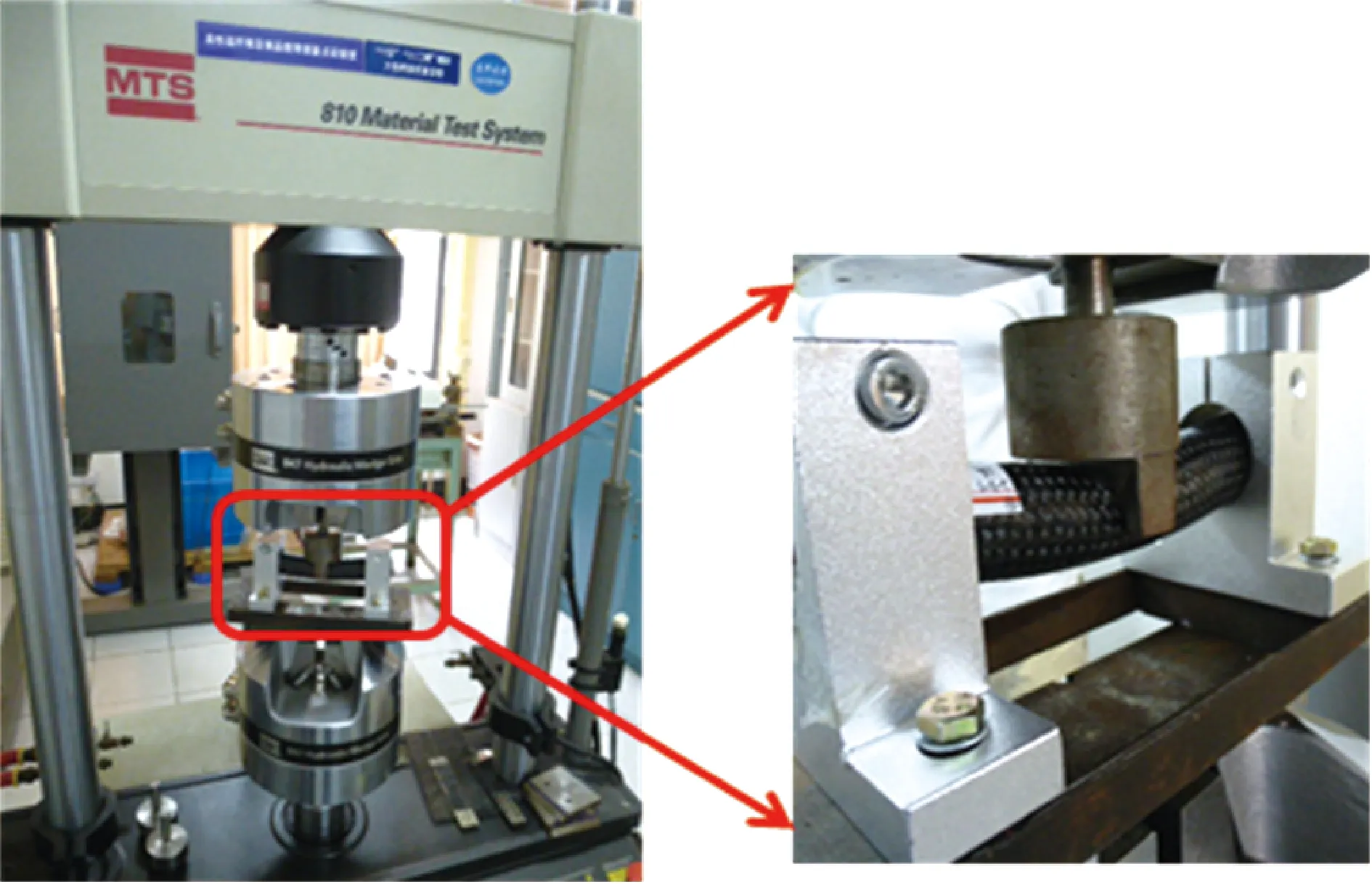
Fig. 3 MTS universal testing machine

Fig. 4 Transverse load-deflection curves for tubes with different braiding angles
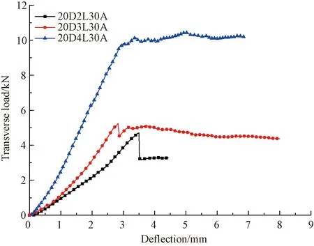
Fig. 5 Transverse load-deflection curves for tubes with different braiding layers

Fig. 6 Transverse load-deflection curves for tubes with different diameters
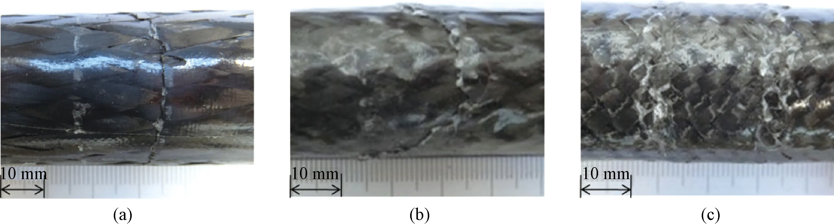
Fig. 7 Damage morphologies of tubes with different braiding angles: (a) 20D3L15A; (b)20D3L30A; (c)20D3L45A
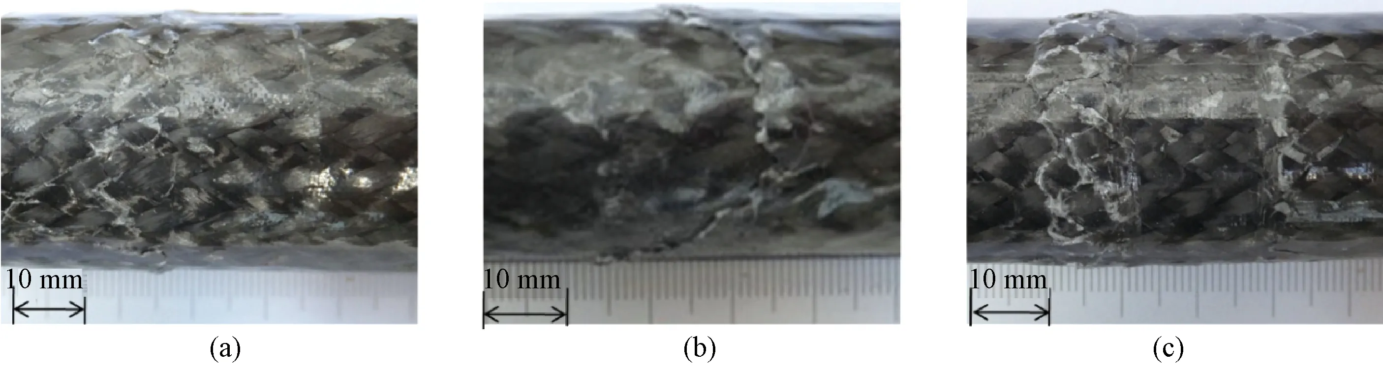
Fig. 8 Damage morphologies of tubes with different braiding layers: (a) 20D2L30A; (b)20D3L30A; (c)20D4L30A
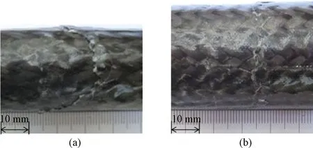
Fig. 9 Damage morphologies of tubes with different diameters: (a) 20D3L30A; (b)25D3L30A
(1)
(2)
whereMis transverse moment,yis the distance between a point and the neutral axis,Iis moment of inertia,Pis the transverse load,Lis the support span,fis the deflection,Dis the external diameter of tubes, anddis the internal diameter of tubes.
2 Results and Discussion
Typical transverse load-deflection curves of 3D circular braided composite tubes under transverse loading test are studied. Linear stages and nonlinear stages are clear in these curves. The linear stage which occurs before the peak load is mainly due to the elastic deformation of the tubes. The transverse load decreases gradually in the nonlinear stage after fiber breakage and the resin cracking. Breaking loads, moduli and strengths of tubes are shown in Table 2. The breaking load increases with the increase of the braiding angle, the wall thickness and the diameter. The modulus increases as the wall thickness and the diameter increase. For different braiding angles, the modulus of specimen with a braiding angle of 30° is the highest. The strength of samples with different braiding angles is similar. As the number of layers increases, the strength decreases first and then increases. The strength increases as the diameter increases.
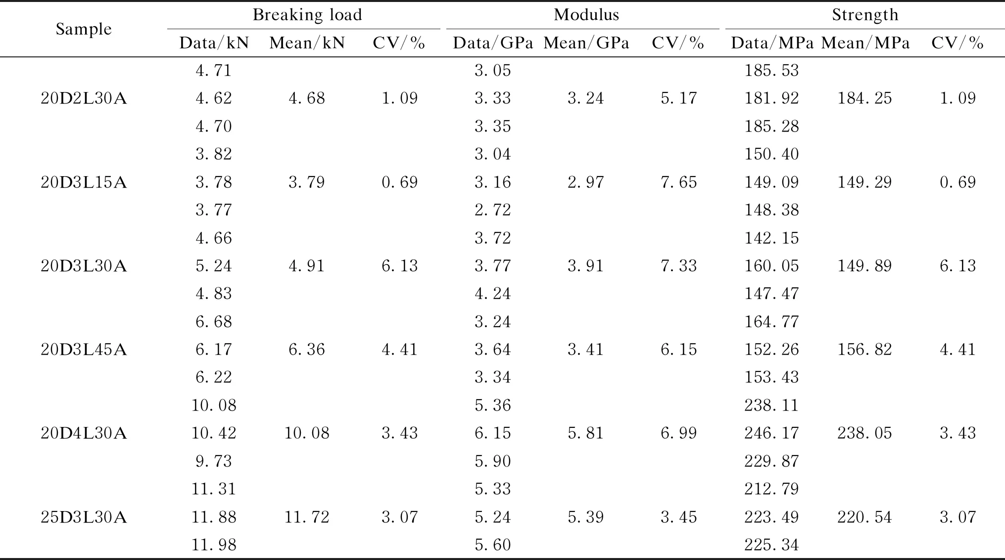
Table 2 Sample braiding parameters and transverse loading properties
2.1 Effect of braiding angle
Figure 4 shows the effects of the braiding angle on the transverse properties of 3D circular braided composite tubes. From the transverse load-defection curves, the bending stiffness and the breaking load increase with the increase in braiding angles. The breaking load of specimen with a braiding angle of 45° is about 1.68 times that of specimen with a braiding angle of 15°. This is mainly because as the braiding angle increases, the yarns are arranged more closely. The increase of local area density increases the ability of anti-deformation and propagation of damage.
2.2 Effect of wall thickness
Figure 5 illustrates the variation in transverse loads of different wall thicknesses with different layers of yarns. It is clear that the bending stiffness and the breaking load increase with the increase of the number of braided layers. The breaking load of specimen with 4 layers of yarns is about 2.15 times that of specimen with 2 layers of yarns. The breaking load of specimen with 4 layers of yarns is about 2.15 times that of specimen with 2 layers of yarns. The increase in bending stiffness indicates that the ability to resist deformation improves with the increase in wall thickness of 3D circular braided composite tubes.
2.3 Effect of diameter
Figure 6 shows the transverse load-deflection curves of tube specimens with different diameters of 20.5 mm and 25.5 mm. The load of the tube with a diameter of 25.5 mm goes up rapidly to the peak load at the linear stage and falls down with a small deflection. Conversely, the load of the tube with a diameter of 20.5 mm goes up gradually before the peak load and falls gradually to a constant value. It is clear that the bending stiffness and the breaking load are higher for the tube with a diameter of 25.5 mm than those for the tube with a diameter of 20.5 mm. The breaking load of the tube with a diameter of 25.5 mm is about 2.39 times that of the tube with a diameter of 20.5 mm. This means that 3D circular braided composite tube with a diameter of 25.5 mm has a superior ability to bear a higher transverse load and resist deformation.
2.4 Failure morphologies
The typical failure morphologies of all specimens are shown in Figs. 7-9. It is clear that the damage concentrates on the contact edges of the semicircle arc head. The main failure modes are indents at the local area in contact with the pressure head, resin crack along the braiding angle, interface debonding and fiber breakage under bending test. 20D3L45A and 20D4L30A with the highest braiding angle and the most layers of yarns respectively, show similar damage morphologies. The area of damage with resin crack and fiber breakage is obviously larger than that of other samples, which means that more fibers carry the load.
3 Conclusions
In this study, the influence of braiding parameters and diameters on the transverse loading behavior of 3D circular braided composite tubes was discussed. The breaking load and the bending stiffness all increase with the increase in the braiding angle, the braiding layers and the diameter. The breaking load of specimen with a braiding angle of 45° is about 1.68 times that of specimen with a braiding angle of 15°. The breaking load of specimen with 4 layers of yarns is about 2.15 times that of specimen with 2 layers of yarns. The breaking load of the tube with a diameter of 25.5 mm is about 2.39 times that of the tube with a diameter of 20.5 mm. The modulus increases as braiding layers and diameters increase. For different braiding angles, the modulus increases from 15° to 30° and decreases from 30° to 45°. The strength of samples with different braiding angles is similar. As the number of layers increases, the strength decreases first and then increases. The strength increases as the diameter increases. The failure points are mainly concentrated on the contact edges of the semicircle arc loading head. The failure modes include local indent, resin crack along the braiding angle, interface debonding and fiber breakage under transverse loading.
 Journal of Donghua University(English Edition)2021年5期
- Journal of Donghua University(English Edition)的其它文章
- Axial Compression Properties of 3D Woven Special-Shaped Square Tubular Composites with Basalt Filament Yarns
- Structural Color Modified Fabrics with Excellent Antibacterial Property
- Parametric Effects on Length of Stable Section of Electrospinning Jet
- Preparation and Performance of Fluorescein Isothiocyanate-Labeled Fluorescent Starch and Polyvinyl Alcohol for Warp Sizing
- Effects of Magnolia denudata Leaf Litter on Growth and Photosynthesis of Microcystis aeruginosa
- Order Allocation in Industrial Internet Platform for Textile and Clothing