
Modeling and character analyzing of multiple fractional-order memcapacitors in parallel connection
2022-01-23 06:37XiangXu徐翔GangquanSi司刚全ZhangGuo郭璋andBabajideOluwatosinOresanya
Chinese Physics B 2022年1期
关键词:徐翔
Xiang Xu(徐翔), Gangquan Si(司刚全), Zhang Guo(郭璋), and Babajide Oluwatosin Oresanya
State Key Laboratory of Electrical Insulation and Power Equipment,Shaanxi Key Laboratory of Smart Grid,
School of Electrical Engineering,Xi’an Jiaotong University,Xi’an 710049,China
Keywords: memcapacitor,fractional calculus,parallel connection,equivalent model
1. Introduction
In 1971, Leon O. Chua postulated a new electrical element called memristor, which described the missing link between the chargeqand the fluxφ.[1]Then the notion of memristor was extended to the memristive system in 1976[2]and generalized to inductive and capacitive elements, named as meminductor and memcapacitor in 2009.[3]As the name implicated, mem-elements have the memory function for the state of history,and their parameter values depend on the polarity, magnitude, and time of the excitation that have been applied. Since a practical memristor device was first realized by HP laboratory in 2008,[4]more researchers began to engage in the related research.[5,6]
At present,many people are working on actual devices or materials[7-10]in the field of the memristor. Although these articles are very creative, the low productivity in laboratories and the different performance of these devices block the advancement of this mem-element. As a forward-looking and instructive work,modeling of memristor can identify some of the potentials of devices that have not yet been applied and guide the research in materials science. Thus, many people have constructed different theoretical models based on the real memory memristors and analyzed the characteristics of their models.[11-14]
Similar to the memristor, memcapacitor is also difficult to manufacture. The modeling of memcapacitor is worth discussing. Up to now, the SPICE circuit of memcapacitor using essential circuit elements is realized.[15]At the same time,the design of memcapacitor emulator based on memristor[16]is proposed because there are constitutive relationships between memory devices. Recently, using the memcapacitor to implement the adaptive neuron is becoming a hot spot.[17,18]There are many related types of research based on the integerorder memcapacitor,[19-21]but few of them are based on the fractional-order memcapacitor.
Fractional calculus[22]is the generalization of integer order calculus, which extends the order of calculus functions from integer to non-integer. Due to the natural objects are generally fractional, it is more accurate than the classical integer methods by using the technique of fractional calculus to describe a real object. Memory effect is another character in fractional calculus. Growing evidence has shown that fractional differential equations can describe many dynamical systems,such as fractional order control,oscillator,chaos systems,and other applications.[23-26]As a result,fractional calculus is used to build an accurate memory device model in this paper.
Fractional-order mem-elements[27,28]are new branches deriving from the above fields. Some researchers have already done the essential work about their characters.[29,30]With the consideration of the memory effect of memory elements, the technique of fractional calculus is used to analyze the characteristics of memcapacitor.The new chaotic system is proposed recently,[31,32]which has been used as a critical component in the fractional-order memcapacitor(denoted as FOMC).Meanwhile,the dynamic characteristics of fractional-order memcapacitor are discussed.[33]Although there are many pieces of related research about FOMC in the neural network[34]and analogue logic circuit,[35]many important areas are still undiscovered.
When there are two or more FOMCs connected in parallel, the dynamic characters are worth considering.[36]Therefore, the model of fractional-order memcapacitors in parallel connection is investigated, and some interesting phenomena are observed in this paper.
This paper is arranged as follows: In Section 2,the basic concept of relations of circuit elements and fractional calculus are recalled. Moreover, a generalized model of the FOMC is introduced. In Section 3, the mathematical model of parallel fractional-order is deduced. In Section 4,a simple form of two FOMCs in parallel is analyzed,and a new way to analyze the FOMCs in parallel connection is proposed. In Section 5, the equivalent memcapacitor of multiple fractional-order memcapacitors in parallel connection is constructed, and the effects ofρandθare analyzed separately. Finally, the conclusions are given in Section 6.
2. Basic concepts
2.1. Relations of circuit elements
There are four fundamental circuit variables, namely,electric currenti, voltagev, chargeq, and magnetic fluxφ,describing the circuit dynamics. The definition of electric currentiis the time derivative of electric chargeq(i= dq/dt).According to the Faraday’s law, voltagevis the time derivative of magnetic fluxφ(v= dφ/dt).
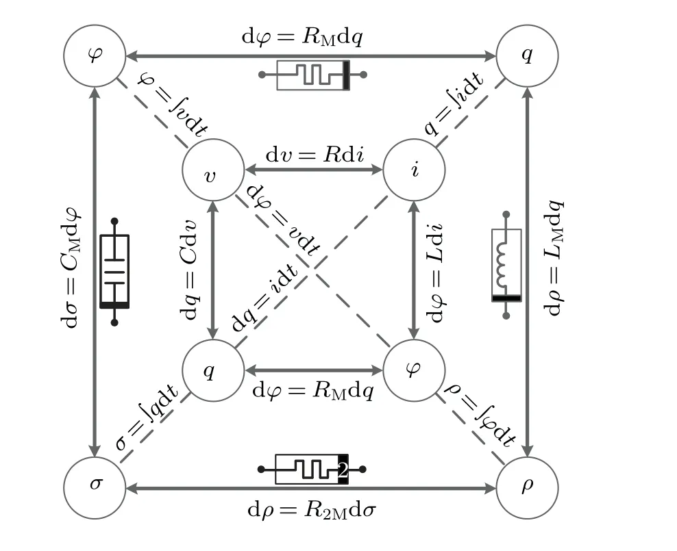
Fig.1. Relations of the fundamental circuit variables.
As mentioned in the other research, Chua noted that another three relations connected pairs of the four fundamental circuit variables and proposed the concepts of memristor,meminductor,and memcapacitor.[1]The memristor is defined by the relationship between the chargeqand the fluxφ:RM=dφ/dq, the meminductor is defined by the relationship between the time integration of flux(ρ=∫φdt)and the chargeq:LM= dρ/dq, and the memcapacitor is defined by the relationship between the time integration of charge(σ=∫qdt)and the flux:CM= dσ/dφas shown in Fig.1.
The memcapacitor is very important in the circuit principle and neural network application research, but the relevant study is far from enough. This paper focuses on the modeling and characteristics of memcapacitor to fulfil imperfections in this part.
2.2. Fractional calculus
Fractional order calculus is the general expansion of the integer order calculus, extending it to an arbitrary order.Growing evidence has shown that fractional differential equations can describe many dynamical systems,for example,fractional order control, DC-DC converters, and other different applications.[13,14]In this section, the fractional-order calculus is introduced in the traditional memcapacitor to make the model more accurate. Thet0Dαtis the fundamental operator used to denoteα-order fractional integral or derivative, defined as
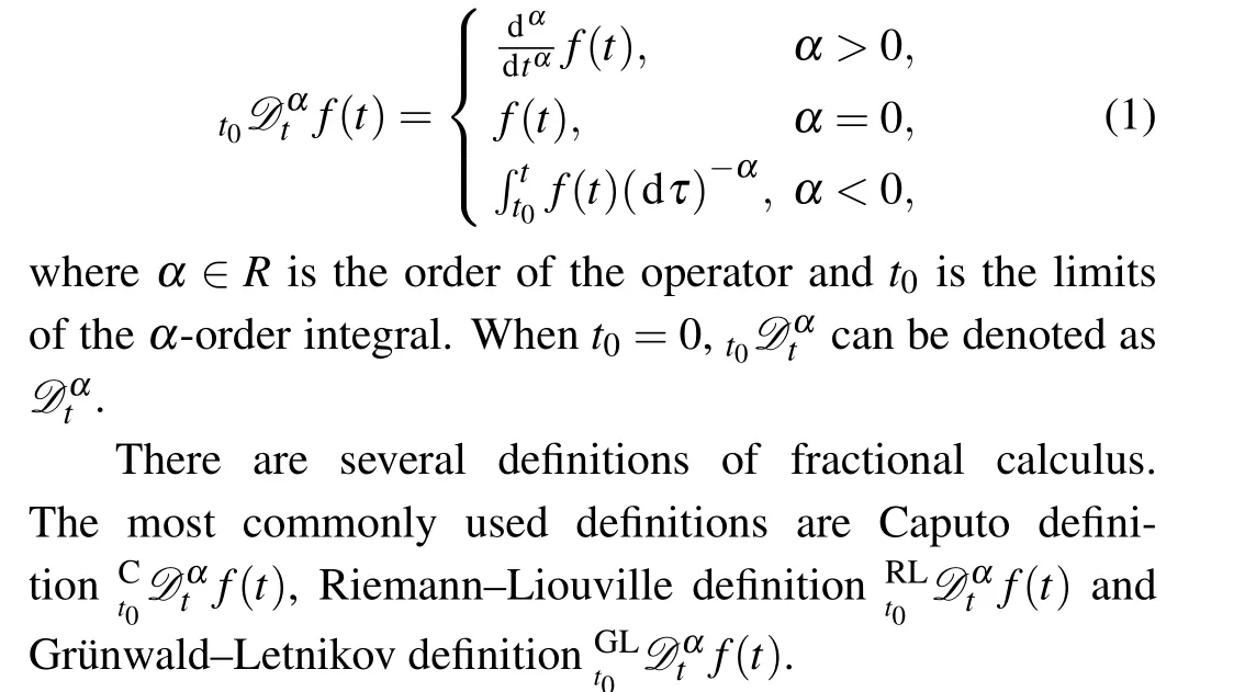
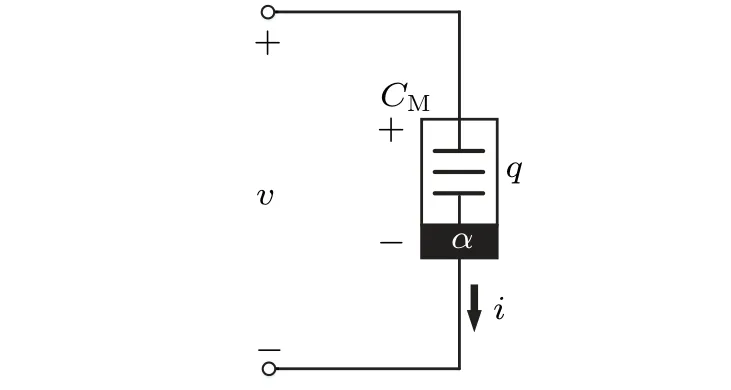
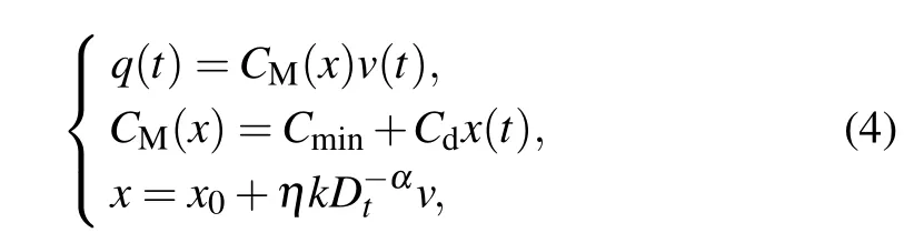
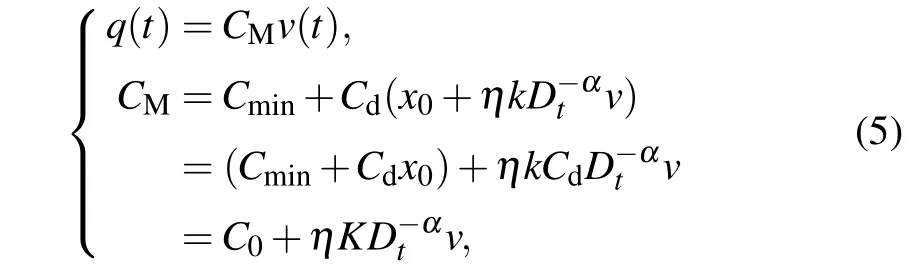
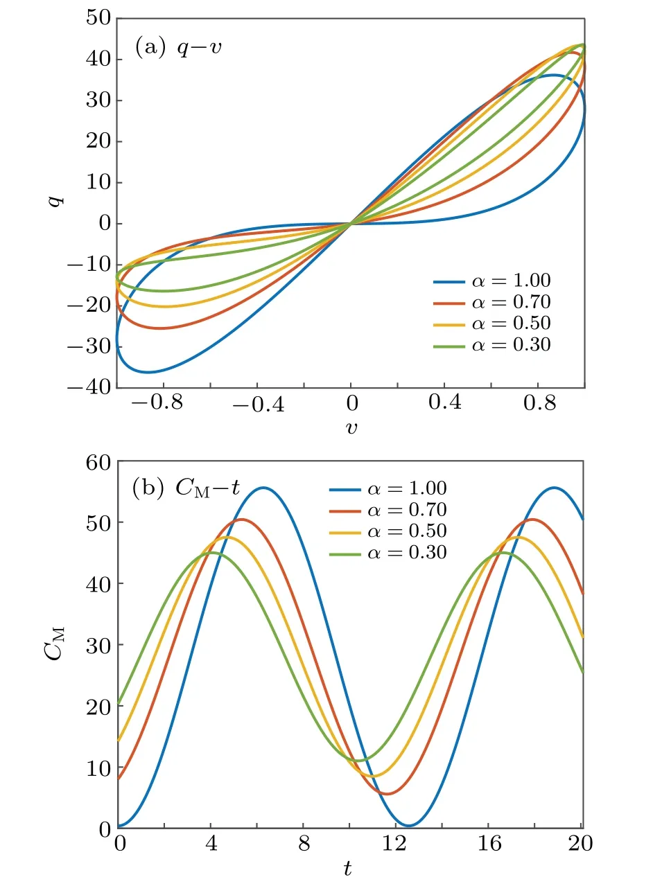
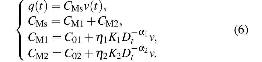
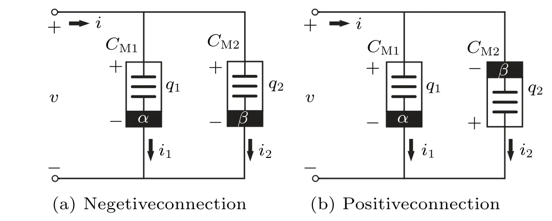
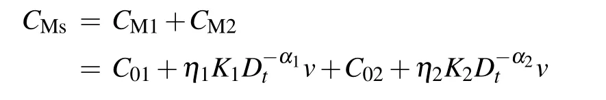
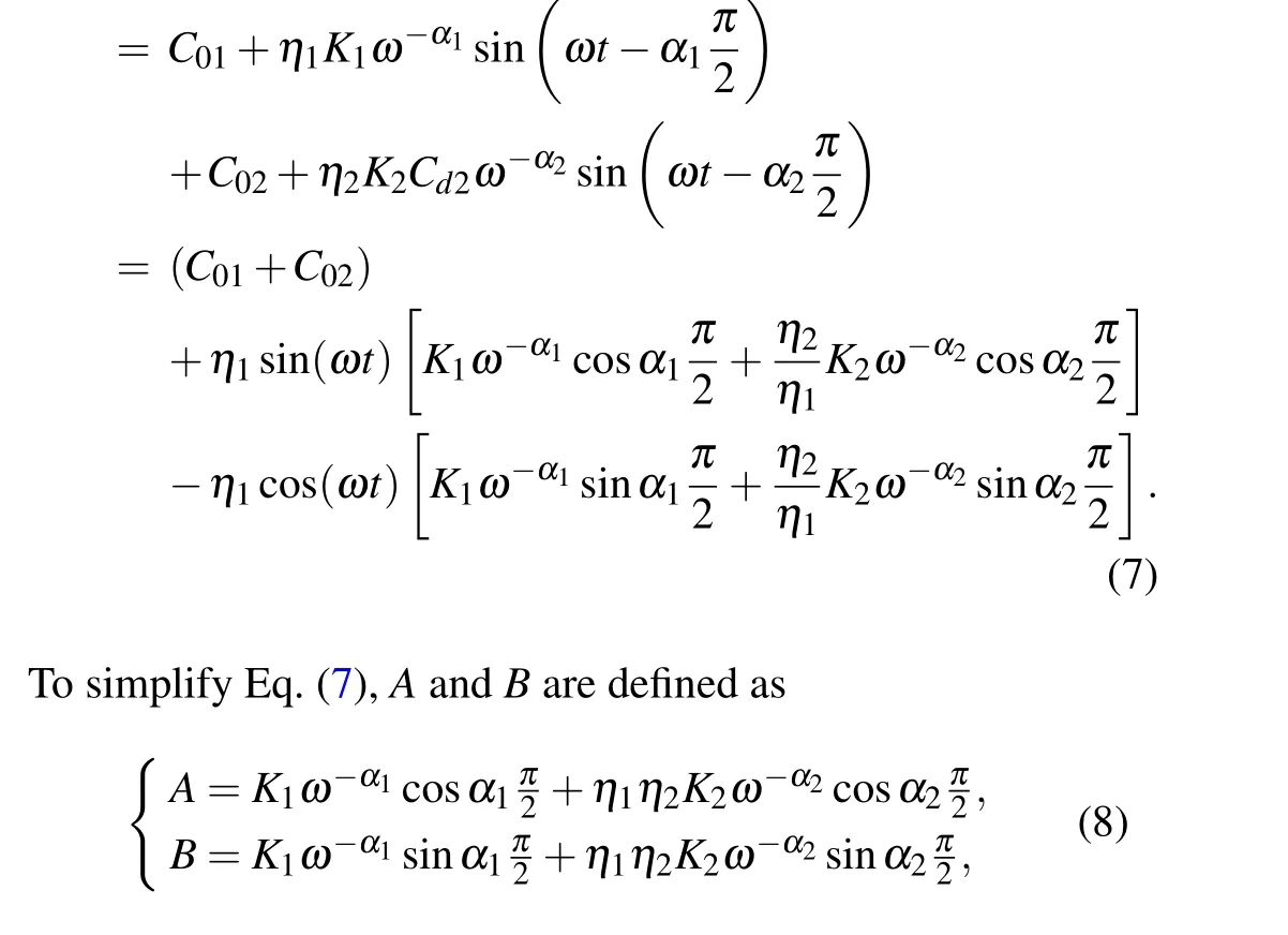
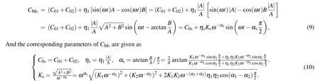
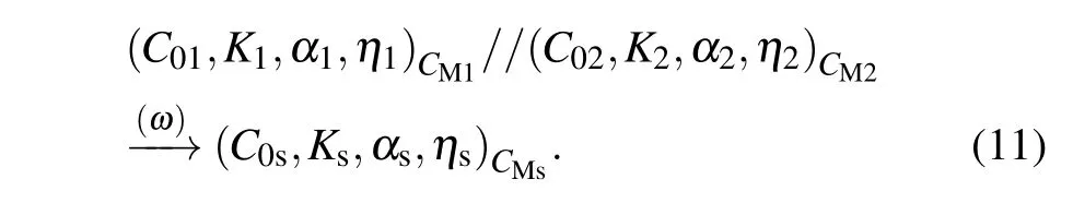
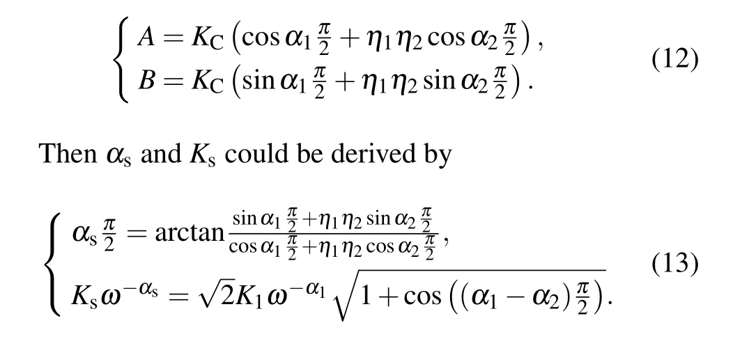
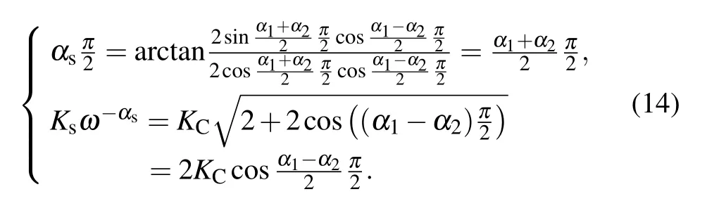
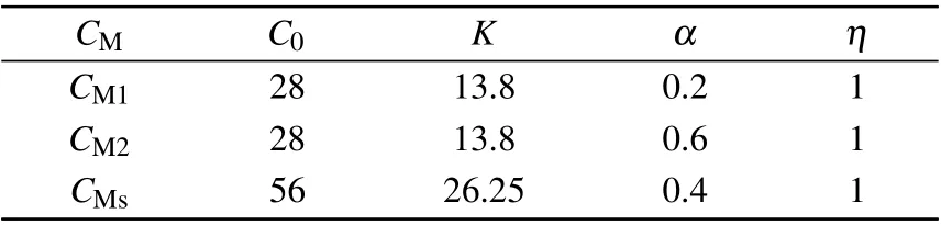
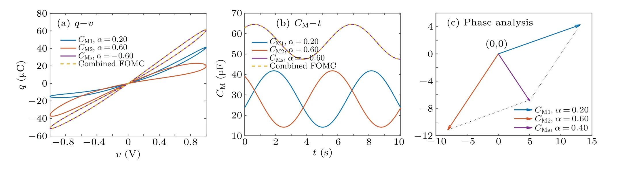
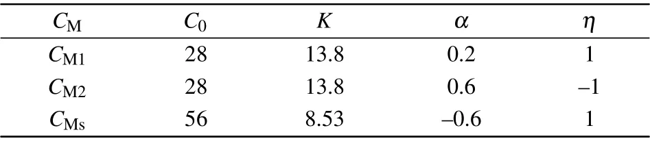
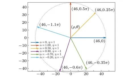
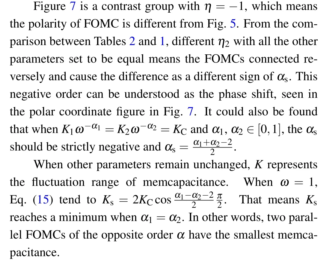
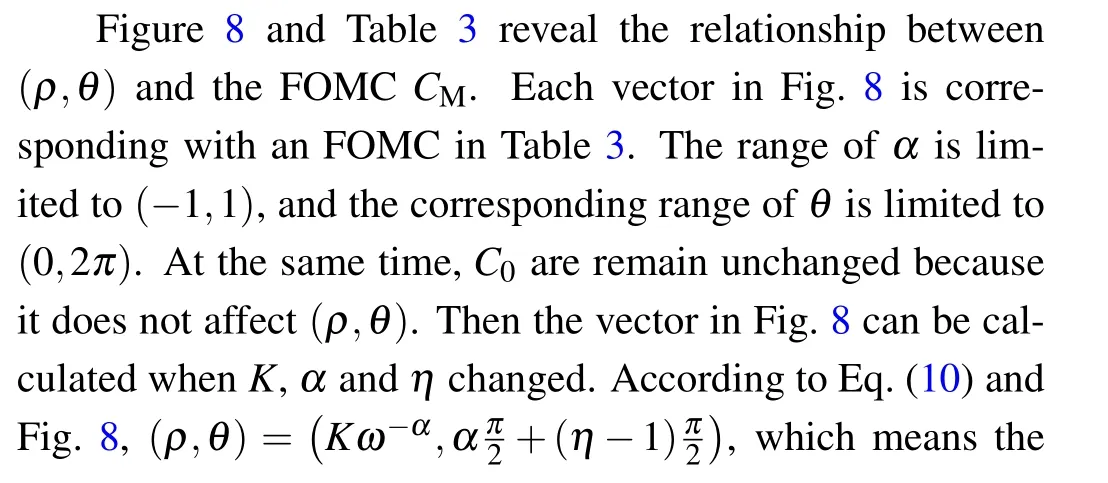
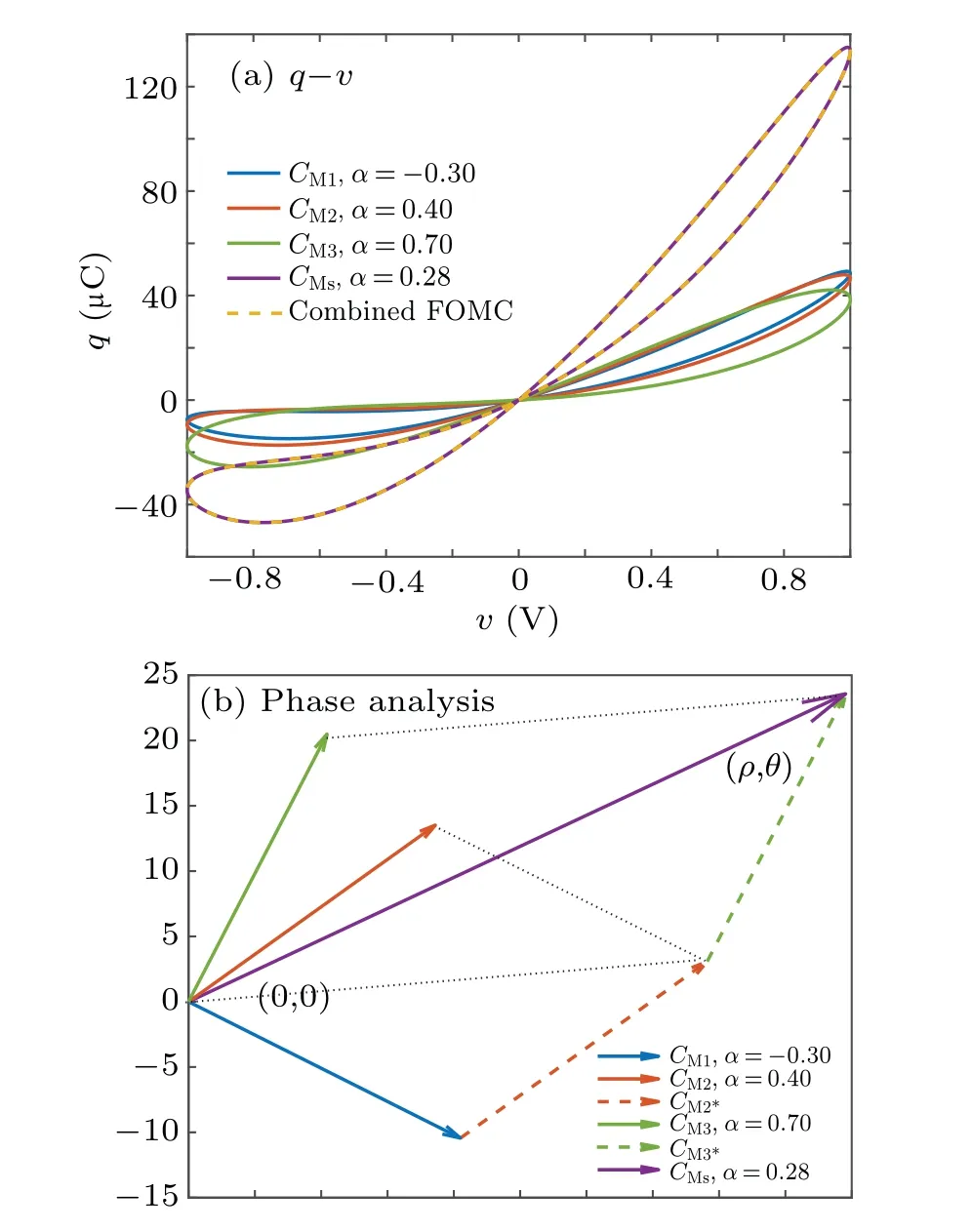
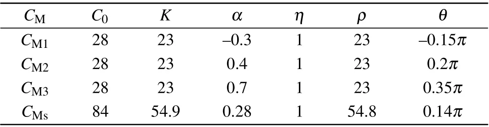
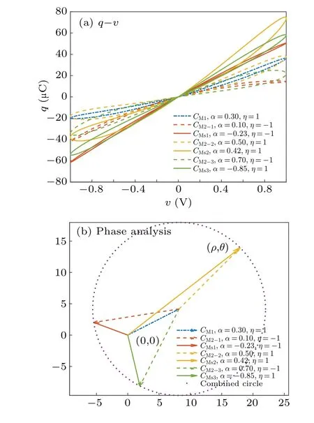
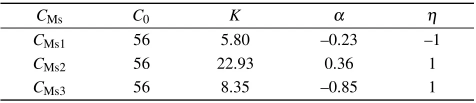
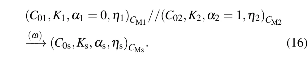
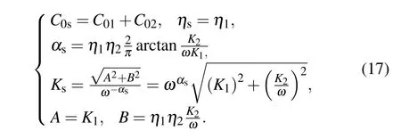
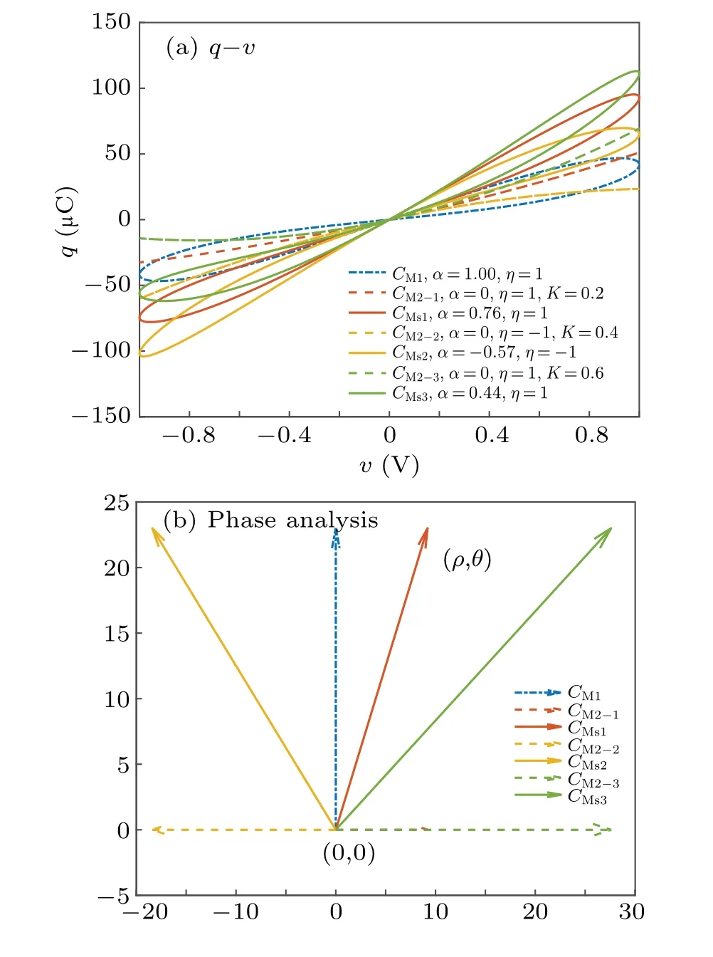
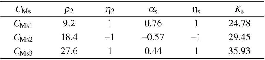
Riemann-Liouville definition and Gr¨unwald-Letnikov definition are equivalent whenf(t) is of classCm, wherem-1≤α The sine function is extremely important for the basic circuit theory,so the sinusoidal resource is mostly used in this paper. By considering the Riemann-Liouville definition and the mathematical method proposed by Radwanet al.in 2013,[38]the fractional-order sine and cosine functions could be calculated as When timettends to infinity, the system is in a stable state,and the sign of approximately equal approaches to the equal. Since the memcapacitor could not be physically implemented with stability and reliability,many emulating methods have been presented to study their dynamic behaviors. In general, mathematical modeling is the most effective method to analyze the circuit based on mem-elements. Figure 2 shows a voltage-controlled FOMC model. Fig.2. A voltage-controlled fractional-order memcapacitor model. According to the generalized model of FOMC proposed in Ref. [28], the state equation of the voltage-controlled FOMC model is given by whereq(t)is the accumulated charge on the memcapacitor at timet, andv(t) is the corresponding voltage.CM(x) is the memcapacitance, which depends on the state of the system,Cd=CMmax-CMmin(CMmaxandCMminare the boundaries of the memcapacitance),x(t)represents the state variable of the memcapacitor withx0=(C0-CMmin)/Cd,whereC0is the initial value of capacitance andx0is the initial value ofx.η=±1 represents the connection way with the applied source. Accordingly,Eq.(4)could also be expressed as whereC0=Cmin+Cdx0,andK=kCd.Thus,the FOMC model could be fully described with four parameters, which can be denoted as(C0,K,α,η)CM. In this paper,the parallel-connected FOMC has been analyzed with sinusoidal excitation,the voltage across the memcapacitor isv(t)=Vmsin(ωt),and theωin this paper is limited to 1 for convenience. Since other model parameters,such as the frequency and amplitude of excitation, have already been discussed in other papers,[29]there will be no more detailed analysis about them in this paper. Fig. 3. Character of fractional-order memcapacitor under sinusoidal signal with different order,α =0.3,0.5,0.7,1. The voltage-controlled memcapacitor model has the characteristic of zero-crossing and hysteresis loop(charge-voltage hysteretic curve) when a sinusoidal voltage is applied, as shown in Fig. 3. The pinch hysteresis loop is an essential characteristic for the memory elements.[37]Figure 3(a)shows the influence of the orderαon the charge-voltage hysteretic curves of the voltage-controlled memcapacitor model. It is found that the curve is bent upward as the parameter orderαdecreases,and the hysteresis curves distorted,which causes it to be asymmetric about the origin. Theηc=1 represents the identical connection,andηc=-1 represents the opposite connection of two FOMCs in parallel. Figure 4 shows the different connections of FOMCs in parallel. The mathematic model of single voltage-controlled FOMC is given by Eq. (3). With the consideration of two FOMCs connected in parallel, the generalized mathematic model can be obtained as Conventionally, the sinusoidal signal is the key in the analysis of any periodic signal. The response of circuit elements is extremely important in many applications. Thus, in this section, the effect of changing the fractional order of the FOMCs will be studied when a single tone voltage is applied and given byv(t)=VMsinωtwithVM=1. Fig.4. Different connections of FOMCs in parallel. Naturally, when two FOMCs are connected in parallel,theCMscan be presented as whereη2/η1=η1η2. Then, the connection of two FOMCs can be rewritten as follows: The memcapacitance of the FOMC is consisted of{C0,K,α,η}. If these FOMCs are denoted as(C0,K,α,η)CM,this equivalent process could be denoted as As a result, the FOMC consisted of two memcapacitors would be a new memcapacitor, whose parameters can all be calculated according to Eq.(10). After discussing the mathematical formula, a proper model is introduced to explain the simplification of multiple FOMCs connected in parallel.This section will describe some basic phenomena based on the theory proposed above. It is assumed that the two devices are identical to make the analysis easier. WhenK1ω-α1=K2ω-α2=KC,we have When connecting in positive and parameterη=η1η2=1,αsandKscan be calculated as The process of parallel connection is shown in Fig.5.Figure 5(a)represents the pinched hysteresis loop of two FOMCs,and Fig.5(b)represents the memcapacitance of them. Fig.5. Two simple FOMCs positive connected in parallel. Table 1. A simple FOMC and its parameters. The purple line is calculated in the normal process, and the dotted line is calculated by the above formula in Figs.5(a)and 5(b). It can be easily seen that the result of the parallel connection matches the formula. More details of the parameters are listed in Table. 1, whereKmeans the rate factors,ηrepresents the different mode of connection andαrepresents the fractional order. But these conclusions cannot be easily seen in Fig.5 and Table 1. At the same time, this description method is not accurate and will bring unintuitive changes due to parameters.There is a new manner of understanding this process, named the polar coordinate method,in which the horizontal and vertical coordinates do not have a special meaning but just a scale of length. The FOMC has four main parameters(C0,K,α,η). The parametersαandKinfluence the equivalent FOMC most whenηis a constant. Their small changes lead to new behaviors and different hysteresis loops. IfKω-αandαπ2 are considered asρandθin polar coordinates, the combination process of (C01,K1,α1,η1)CM1and (C02,K2,α2,η2)CM2could be illustrated as shown in Fig. 6. The equivalent modeling structure could be explained conveniently,and the two parametersρandθcan intuitively show the effect of the combination. Fig.6. Two simple FOMCs positive connected in parallel. From Table 1 and Fig. 6, the parameters of equivalent FOMCs could be easily calculated when two FOMCs with identical polarities andK1ω-α1=K2ω-α2=KC.αsis precisely the mean value ofα1andα2. Meanwhile, the equivalent process could be calculated by equations and illustrated by the polar coordinates form with the fluctuation range and phase changes equivalent toρandθ. When connected in negative, which meansη1η2=-1,αsandKscan be obtained as follows: Then,the parameters are chosen as shown in Table 2,and the correspondingv-qand other curves are shown in Fig.7.stants to make Fig.8 more intuitive in showing the relationship betweenα,η,ρ,andθ. Fig.7. The negative order of FOMC and its components’s order. Table 2. The negative order FOMC(α<0)and its component FOMCs(α >0). Fig.8. Different(α,η)and corresponding polar coordinates. The purple line is calculated in the normal process, and the dotted line is calculated by the above formula in Fig. 7.It can be easily seen that the result of the parallel connection matches the formula. At the same time, whenη=-1, the area of the pinch hysteresis loop is minor thanη=1 in Fig.5 with all the same parameters of others. It means the parallel directions lead to this difference. In other words,two FOMCs connected in parallel in identical polarities produce a superposition effect, and two connected in opposite polarities have a reduction effect. Some interesting phenomena show up during the process of reconstruction. One of the most important phenomena is the equivalent negative order. As shown in Fig.7,two general positive FOMCs connected in parallel can be constituted into an equivalent FOMC with negative order. By using polar coordinates, differentCMcould be illustrated in Fig. 8. The parametersC0andKare set to be con- Parameterθrotates counterclockwise in(0,2π),and the parameterρmeans the length of polar coordinate, which is a constant in Fig. 8. As shown in Figs. 5-7 , parameterρis positively correlated with the fluctuation range of memcapacitance,and the parameterθdepends onαandη. (ρ,θ)are the critical parameters in the calculation of parallel FOMCs. In this section,two FOMCs with their parameters chosen appropriately can constitute a new FOMC whose order is negative. Furthermore,FOMC with negative order could be generally constituted through combining two FOMCs in opposite polarities. Also, all theCMcould be described in the form of polar coordinates, which will make the equivalent process convenient. After analyzing the two typical FOMCs connected in parallel with identical or opposite polarities,the combination process in some complex situations will be discussed in this section. Firstly, multiple FOMCs connected in parallel will be analyzed and illustrated in Subsection 5.1. According to Eq. (10), it is easy to have two FOMCs in parallel together as a new equivalent FOMC, while it is hard to directly combine several FOMCs and get a result for the parameters(C0,K,α,η)ofCMs. Combining with the conclusion that two devices in parallel can be equivalent to the addition of two vectors,it can be easily derived that many FOMCs linked in parallel can be calculated one by one as vectors. Thus, by continuously combing the equivalent FOMC calledCMswith the new FOMC, the multiple FOMCs connected in parallel could also be easily combined as the equivalent FOMC. The parameters of the equivalent FOMC can also be calculated by Eqs.(13)and(15)step by step. The process of combination is shown in Fig. 9, and the corresponding parameters of FOMCs are listed in Table 4 analysis of the fractional-order memcapacitor. The purple line is calculated in the normal process, and the dotted line is calculated by the above formula in Fig.9(a).It can be easily seen that the result of the parallel connection matches the formula.CM1,CM2,andCM3are three initial vectors whose colors are blue,orange and green,respectively.The orange dotted line is the translation of the orange vectorCM1and the green one is vectorCM2. After a simple vector superposition,the combined FOMC namedCMsis shown as the purple vector. The parameters ofCMsare calculated by Eqs.(13)and (15) and shown in Table 4. In this way, the difficult-tocalculate fractional problem is easily converted into vector addition,and the same result is obtained. The polar coordinates diagram intuitively shows the parallel process of the FOMCs comparing with the traditional hysteresis loop diagram. Fig.9. Multi FOMCs connected in parallel. Table 4. Multi FOMCs and their corresponding CMs. As shown in Fig.9(b),the combination process for multi FOMCs is much easier to understand as polar coordinates compared with using Eq. (10). The equivalentCMscould be constituted by connecting polar coordinates form of multi FOMCs one after another. Besides combining two FOMCs,multiple FOMCs could also be constituted into an equivalent form with all parameters reconstructed. When considering the polar coordinates form of FOMCs, there are two crucial parametersρandθ. The impact of each parameter will be discussed separately in Subsections 5.2 and 5.3. The parameters ofCM1remain consistent as (C01=28,K1=9.2,α1=0.3,andη1=1). The differentCM2with distinctiveθare connected withCM1. The corresponding curves are shown in Fig.10(b). TheCM2-1,CM2-2, andCM2-3are obtained by only changingθwhen the other parameters are consistent. The orange,green,and yellow dotted lines in Fig.10 represent these three vectors, respectively.CMsis an equivalent combination ofCM1andCM2. The combination ofCM1andCM2namedCMs1,CMs2,andCMs3are drawn as orange,green,and yellow vectors, respectively. Similarly,CMsis calculated using the method in section 5.1 and shown as Fig.10(b). Figure 10(a) is the intrinsic characteristics of memelements-hysteresis loop,and Fig.10(b)is the polar diagram.When multiple FOMCs are involved in parallel connection,the hysteresis loop is complicated and challenging to feel intuitive. The comparison of Figs. 10(a) and 10(b) shows the simplicity and clarity of the polar coordinates in the parallel connection calculation. Fig.10. FOMCs connected with different θ. Table 5.The different parameters α and η of CMs caused by the change of CM2. When changingθwith other parameters unchanged,vectorCM2will move in a circle whose radius isρ. At the same time,θmeans different parametersαandηinCMsshown in Table 5. The parametersC02=28 andK2=13.8 remain consistent withα2={0.1,0.4,0.7}andη2={-1,1,-1},which meansθofCM2varies. At the same time, the parameters ofCMsvary as Table 5 list. The process of combination are shown in Fig.10(a). When the polar coordinates form ofCM1drawn located in the combined circle, that is,ρ1<ρ2, as shown in Fig. 10(b),the value ofρsorKsvaries between[ρ2-ρ1,ρ2+ρ1]and the value ofθscould range the whole 2πperiod,behaving as differentαsorders andηs,which means the negative order could undoubtedly appear. Whereas whenρ1>ρ2,there have a chance that the sign ofηsandαkeeps unchanged if the parameters ofCM1andCM2are appropriately chosen. It could also be easily found that using the polar coordinates form and drawing the combined circle is a very convenient way to analyze the effect ofθ.As theθ1,2changes,θsandρschange together with the sign ofαsandηs. The use of the polar coordinate method can offer a new angle to understand the fractional-order mem-elements. Since the combination of orderα1,2∈(0,1)is already appeared and analyzed several times in the above paragraphs,the fractional-orderα1andα2are chosen asα1=0 andα2=1 to make sure thatθis unchanged and the impact of differentρwill be discussed here,which means Then according to Eq.(10),the following equation could be derived withα1=0,andα2=1: The parameters ofCM1remain consistent as(C01=41.8,K1=23,α1=1,andη1=1).C02andα2ofCM2also remain asC02=41.8,andα2=0. Other different parameters ofCM2andCMsare shown in Table 6. Then the corresponding curves are shown in Fig.11. Figure 11(a) is still a hysteresis loop diagram, which is more complicated and can explain that devices are memelements. Figure 11(b)is the polar diagram ofCM1,CM2,andCMswhenθare unchanged. In Fig. 11(b), other parameters ofCM1andCM2are unchanged whenρandηare variable. In other words,the fractional-order are chosen asα1=0,α2=1,η1=±1, andη2=±1. According to the fact that any twodimensional vectors can be obtained by two vectors with different directions in this flat.CMscan be FOMC whose parameters are arbitrarily specified. Fig.11. Multi FOMCs connected in parallel. Table 6. Different ρ and corresponding CMs. In Fig.11,the orange,green,and yellow dotted lines representCM2-1,CM2-2,CM2-3, respectively, and the blue one representsCM1. The combination ofCM1andCM2namedCMs1,CMs2,andCMs3are drawn as orange, green, and yellow solid vectors,respectively. It could be easily observed that two integral orders are combined to constitute an equivalent fractional order,that is to say, 0<|αs|<1 being a fractional-order whereas theα1=1 andα2=0 being integral orders. In this case, the equivalent method establishes the relationship between FOMC and general mem-elements. As shown in Fig.11,differentρ2orK2leads differentρsandθs,where the value ofθsis located between theθ1andθ2and closer to the FOMC with the biggerρ. The FOMC with a biggerρmeans it has a more significant weight coefficient in the equivalent parameter. Although several different pairs ofCM1andCM2could combine equivalentCMs,a simple method to constitute a specifiedCMscould be employed according to Eq.(17)and Fig.11.Also, by lettingα1=0 andα2=1, other parameters ofCM1andCM2could be calculated by Eq.(18),which is directly derived from Eq. (17) when the parameters ofCMsare already specified. In Subsection 5.3, it is found that two integral order memcapacitor could be connected in parallel to constitute an FOMC. Therefore it leads to a simple way to constitute an order-specifiedCMswith Eq. (18). Meanwhile, it could be more available since the device of integral order memcapacitor is much easier to be obtained. The parameters’values ofCM1andCM2could be easily calculated, and the process of combination is straightforward with Eq.(18). This paper discussed the generalized model of voltagecontrolled fractional-order memcapacitor and mostly considered the parallel-connected FOMCs. The behavior of parallelconnected FOMCs is explored, and some conclusions are made. Two fractional-order memcapacitors are connected in parallel with identical and opposite polarities, the equivalent model is derived,and the characteristic of the equivalent order is analyzed. For general FOMCs, the fractional-orderα ∈(0,1).FOMCs connected in parallel with identical polarities produce superimposing effect when rate factorKincrease and the amplitude fluctuation range increase withK. FOMCs connected in parallel with opposite polarities produce a cancelation effect when the rate factorKdecreases and the amplitude fluctuation range decreases withK. Additionally, the negative order appears,and the situations when it happens are discussed clearly. This paper proposes a new simplified calculation method based on the new generalized model and the most basic sine wave compared with the previous highly complicated fractional-order calculations of other investigations. This method can solve the problem in a stable system that satisfies the conditions in Subsection 2.2. Then a new understanding manner by using polar coordinates is derived to explain the equivalent modelling structure conveniently. The new polar coordinates method is relatively concise and clear to illustrate the fractional-order change and amplitude fluctuations. Accordingly,multiple fractional-order memcapacitors could be calculated into one composite memcapacitor with its key parameters(C0,α,η)reconstructed by Eqs.(13)and(15).Meanwhile, two integral order memcapacitors could be connected in parallel to constitute an FOMC, which means the fractional orders memcapacitors could be constructed into arbitrary orders by the method referred to in Subsection 5.3.Additionally,in some oscillator circuits,this method of designing FOMC parameters is also advantageous. In future work, this research will be extended to all fractional-order mem-elements and hybrid connection methods. Acknowledgement Project supported by the National Natural Science Foundation of China(Grant No.52077160).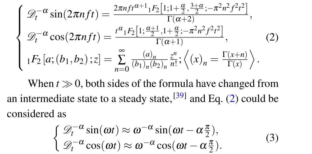
2.3. Modelling of fractional-order memcapacitor
3. Modeling of two FOMCs in parallel
4. Character analyzing of FOMCs in parallel connection
4.1. Two typical FOMCs connected in parallel with identical polarities

4.2. Two typical FOMCs connected in parallel with opposite polarities

5. Equivalent of multi FOMCs in complex situations
5.1. Illustrating of multi FOMCs connected in parallel
5.2. FOMCs connected with different θ
5.3. FOMCs connected with different ρ and the constitution of arbitrary order FOMCs

6. Conclusion
猜你喜欢
中国储运(2022年10期)2022-11-08
中国储运(2022年8期)2022-09-06
中国储运(2022年5期)2022-05-12
中国储运(2022年3期)2022-03-22
———2022货运再出发
中国储运(2022年3期)2022-03-22
中国储运(2019年12期)2019-12-17
中国储运(2017年12期)2017-12-04
中国储运(2017年9期)2017-09-07
故事会(2017年12期)2017-06-22
三联生活周刊(2017年9期)2017-03-03

- Chinese Physics B的其它文章
- Superconductivity in octagraphene
- Soliton molecules and asymmetric solitons of the extended Lax equation via velocity resonance
- Theoretical study of(e,2e)triple differential cross sections of pyrimidine and tetrahydrofurfuryl alcohol molecules using multi-center distorted-wave method
- Protection of entanglement between two V-atoms in a multi-cavity coupling system
- Semi-quantum private comparison protocol of size relation with d-dimensional GHZ states
- Probing the magnetization switching with in-plane magnetic anisotropy through field-modified magnetoresistance measurement