
Bright 547-dimensional Hilbert-space entangled resource in 28-pair modes biphoton frequency comb from a reconfigurable silicon microring resonator
2022-02-24 09:38QilinZheng郑骑林JiachengLiu刘嘉成ChaoWu吴超ShichuanXue薛诗川PingyuZhu朱枰谕YangWang王洋XinyaoYu于馨瑶MiaomiaoYu余苗苗MingtangDeng邓明堂JunjieWu吴俊杰andPingXu徐平
Chinese Physics B 2022年2期
Qilin Zheng(郑骑林), Jiacheng Liu(刘嘉成), Chao Wu(吴超), Shichuan Xue(薛诗川),Pingyu Zhu(朱枰谕), Yang Wang(王洋), Xinyao Yu(于馨瑶), Miaomiao Yu(余苗苗),Mingtang Deng(邓明堂), Junjie Wu(吴俊杰), and Ping Xu(徐平),3,‡
1Institute for Quantum Information and State Key Laboratory of High Performance Computing,College of Computer,National University of Defense Technology,Changsha 410073,China
2College of Advanced Interdisciplinary Studies,National University of Defense Technology,Changsha 410073,China
3National Laboratory of Solid State Microstructures and School of Physics,Nanjing University,Nanjing 210093,China
High-dimensional entanglement provides valuable resources for quantum technologies, including quantum communication, quantum optical coherence tomography, and quantum computing.Obtaining a high brightness and dimensional entanglement source has significant value.Here we utilize a tunable asymmetric Mach–Zehnder interferometer coupled silicon microring resonator with 100 GHz free spectral range to achieve this goal.With the strategy of the tunable coupler, the dynamical and extensive tuning range of quality factors of the microring can be obtained, and then the biphoton pair generation rate can be optimized.By selecting and characterizing 28 pairs from a more than 30-pair modes biphoton frequency comb, we obtain a Schmidt number of at least 23.4 and on-chip pair generation rate of 19.9 MHz/mW2 under a low on-chip pump power,which corresponds to 547 dimensions Hilbert space in frequency freedom.These results will prompt the wide applications of quantum frequency comb and boost the further large density and scalable on-chip quantum information processing.
Keywords: silicon microring resonator,quantum entanglement,biphoton frequency comb
1.Introduction
With the prosperity of the photonic quantum industry,numerous applications with the practical value from quantum computing to quantum communication[1,2]have emerged.Lying at the heart of these quantum technologies, quantum light sources[3]provide available resources and endue them with quantum advantages.High-dimensional entanglement is one of the valuable resources for supporting high capacity quantum communication,[4]quantum optical coherence tomography (QOCT),[5]high-dimensional one-way quantum processing,[6]and error-tolerant quantum computation.[7]However, it is still a challenge to further expand the scale of quantum applications because of the limited quantum resources.One of the solutions can be increasing the physical qudits or the entanglement dimensionality.[8]As a feasible approach to improve entanglement,the biphoton frequency comb (BFC)[9]has been widely studied.As one of the most promising architectures,the quantum photonic chips have the merits of miniaturization, reconfigurability, high integration,high stability,mass production,and so on.[10]For on-chip applications,frequency should be a prominent degree of freedom for scaling the Hilbert space in a single waveguide mode without occupying a large physical space of the chip.Quantum interference and logic gates in frequency space have been successfully demonstrated.[11,12]
The higher dimensionality usually implies the higher ability achieved in quantum tasks; hence a high-dimensional frequency entanglement is a long-time goal in this field.How to further increase the dimensionality is of significant value.Usually, in order to evaluate the entanglement dimension of BFCs,we can measure their joint spectral intensity(JSI),and then calculate the Schmidt number[13]through singular value decomposition to give the entangled dimensionality.To our knowledge, BFCs have been generated from different photonic chip platforms[14]like the third-order nonlinear platform including silicon-on-insulator(SOI)[15–17]and silicon nitride (SiN),[18,19]the second-order nonlinear material,[20,21]and high refractive index glass.[22]The Schmidt numberKin the frequency freedom obtained from the measured JSI is at most 22.0[15]by measuring both the JSI and unheralded second-order correlationg(2).[23]For the BFCs from silicon nitride microring resonator, the gained maximum Schmidt number is 20.[18]In Ref.[19], the authors observed 37 mode correlated pairs from a 42-pair BFC with a pump power larger than 20 mW,while there was no detailed calculation about the Schmidt number.Chang realized a BFC from a second-order nonlinear PPKTP waveguide with a fiber Fabry–Prot cavity as the post-selection,and the Schmidt number was calculated to be 18.3.[20]An earlier version of this BFC source was characterized with no more than 9 frequency modes.[21]Kumar obtainedK=10.6 from a periodic sequence of coupled silicon microresonators chain.[16]In Ref.[22],the authors achieved a quantum system through two entangled qudits of high refractive index glass BFC,and they characterized the limited modes and obtained a Schmidt number of 10.
The dimensionality and brightness of the BFCs are one of the main concerned parameters that guarantee a high-quality BFC generation.[24]In this work, we demonstrate a reconfigurable silicon microring resonator, aiming to generate a high brightness and dimension biphoton frequency comb at a low-power consumption that can be widely adopted for further large density on-chip quantum information processing.For increasing the dimensionality, we design a relatively large circumference to obtain a small free spectral range(FSR), i.e., a 100 GHz frequency spacing between adjacent frequency modes.With recently developed high-speed lithium niobate on insulator (LNOI) electro-optic modulators,[25,26]the 100 GHz spacing frequency comb can be manipulated for quantum information processing.[12]For the brightness, we propose to adopt the asymmetric Mach–Zehnder interferometer (AMZI) as the tunable coupler for the microring to offer a tuning range of quality factors to optimize the brightness or pair generation rate (PGR) of the biphoton frequency comb.Experimentally, we fabricate a CMOS-compatible silicon chip that is an efficient nonlinear platform for lowering the required pump power.An at least 23.4-dimensional frequency entanglement spanning 547 dimensional Hilbert space resource with on-chip pair generation rate of 19.9 MHz/mW2is obtained at a low on-chip power.
2.Theory and experiments
The AMZI-coupled microring resonator was firstly proposed by Barbarossa in Ref.[27], then has been widely used for tunable filtering,[28]sensing,[29]and improving the PGR[30]of photons.Here,we dynamically modulate the quality factorQof the microring with this AMZI as the coupler,then optimize the PGR and characterize the dimensionality of quantum entanglements around this high PGR working point.The AMZI-coupled microring is shown in Fig.1(a).The silicon waveguide covered with SiO2has a width of 500 nm and a height of 220 nm.The two gaps between AMZI and the microring are both 200 nm which guarantee that the microring can be in different coupling status, and the length difference between the two arms of AMZI is 2πR,whereRis the radius of the microring with 112µm that corresponds to the 100 GHz free spectral range (FSR) which is compatible with commercial dense wavelength division multiplexing(DWDM).TheQfactors of the AMZI-coupled microring can be expressed as
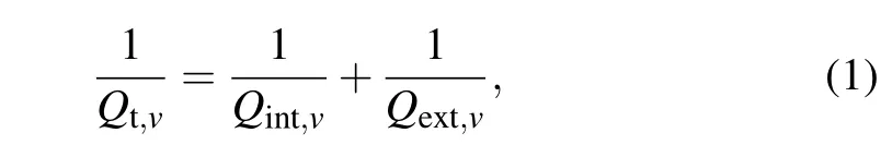
whereQt,QintandQextare the total, intrinsic and extrinsic quality factors, respectively, the subscriptvrepresent pump(p), idler (i) or signal (s).Besides,Qint=ω/(Vgα) is determined by the round-trip loss coefficient α inside the ring.TheQext=2πRω/(Vg|Ke|2) is related to the equivalent coupling coefficientKebetween the microring and waveguide.HereVgis the group velocity of the ring,Ris the microring radius,and ω is the center angular frequency.Combine all-pass microring theory and the AMZI theory,[27]Ke= itk(e−i(βΔL+Ψ)+1),wheretandkare the electric field amplitude coupling coefficient and transmission coefficient of the coupler satisfyingt2+k2=1,β is the propagation constant related to the wavelength, ΔLis the arm length difference, and Ψ is the modulation phase controlled by the voltage applied on the resistive heater of the thermal-optic phase shifter.Figure 1(b) shows the theoretical transmission efficiency and|Ke|2changing with wavelength under two different Ψ.The phase Ψ can modulateKeand then the extrinsic quality factorQextandQint/Qextcan be modulated.According to the different values ofQint/Qext,we can divide the working status of the microring into three regions.Specifically,whenQint/Qext=1,the amplitude in the microring can be maximized, and the transmission efficiency at this point is near 0.We call this state critical-coupling and define the|Ke|2in this point as|Kc|2.WhenQint/Qext>1,that means|Ke|2>|Kc|2,the state turns into over-coupling,and the most over-coupling point refers to the coupling state when the maximum value ofQint/Qextis achieved on the structure we use.While whenQint/Qext<1,that means|Ke|2<|Kc|2,the state becomes under-coupling.Under different coupling situations, we can get different spontaneous four-wave mixing(SFWM)efficiencies.
From the references,[3,31]the PGR of them-th pair spectral modes is closely related to the value ofQint/Qext.Specifically,
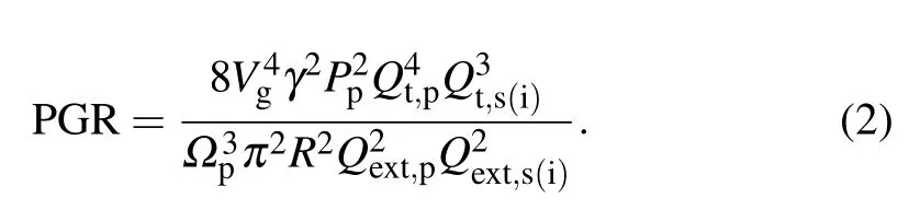
Among them, γ is the nonlinear parameter of χ(3),Ppis the pump power, and Ωpis the resonance frequency of the pump light.Qextis the extrinsic quality factor of them-th entangled frequency photon pair that varies with Ψ,which can be given by the following formula:
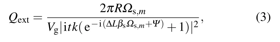
where Ωs,mis the resonate frequency and βsis the propagation constant of them-th mode signal photon.Since ΔL=2πRwill lead to the extrinsic quality factors of all resonance modes including pump,signal,and idler being the same,and therefore the total PGR of all frequency modes can be finally expressed as a function ofQint/Qextwhich is in the same form of them-th frequency pair’s PGR.In fact,when the microring is manufactured with a fixed ΔLand coupling gap, we can change the voltage applied to AMZI, thereby equivalently changing the coefficientKe, and then determiningQand further affecting PGR.
The experimental schematic is shown as Fig.2.A tunable laser is coupled into the silicon chip through the on-chip grating, and the BFC from SFWM inside the microring is generated and coupled out again through an on-chip grating then passes through a filtering system to reach superconductor nanowire single-photon detectors(SNSPD)finally.When the pump laser at 1549.315 nm was coupled to and decoupled from the chip by coupling fiber arrays and the waveguide grating array, the total insertion loss was about 7.68 dB and each facet insertion loss was about 3.84 dB.We define the onchip pump power as the power that is coupled into the chip through one facet coupling for fiber arrays to the waveguide grating array with an insertion loss of 3.84 dB.Before this,the pump power has suffered a transmission loss of 0.47 dB,then passes through the polarization controller and filter with a loss of 1.14 dB.The tunable CW laser has a line width of 0.4 MHz and a wavelength tuning range of 1500 nm to 1630 nm.The adjustment accuracy of the temperature controller (TEC) for the silicon chip is 0.01°C; it is an automatic temperature adjustment system combining a Peltier with a negative feedback module.The tunable filter supports independently tunable center wavelength and bandwidth.It has a 1525 nm to 1610 nm tuning range and 0.08 nm minimum filter bandwidth;when the bandwidth is set to 0.2 nm,the insertion loss is about 6 dB.The digital-to-analog voltage converter(DAC)is an adjustable voltage controller with 8 channels, and each channel has an accuracy of 0.01 V.The timing analyzer (TA) has a 78 ps time bin width.Besides, the dark counts of the two SNSPDs are 150 Hz and 200 Hz,with efficiencies of 74% and 75%,respectively.

Fig.1.(a)The structure of the experimental AMZI-coupled microring,the resistive heater can be powered through the metal pads.The k refers to the electric field amplitude coupling coefficient,and t refers to the electric field amplitude transmission coefficient that satisfies t2+k2=1.(b)The theoretical transmission efficiency and|Ke|2 changing with the wavelength under two different phases.When the phase changes from Ψ =0 to Ψ =0.66π,the transmission efficiency becomes smaller because of the equivalent change of Ke.
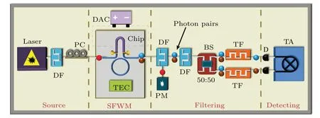
Fig.2.The schematic diagram of our experiments.Here, PC, polarization controller; PM, power meter; BS, beam splitter; D, superconducting nanowire single-photon detector(SNSPD);TEC,temperature controller,it is an automatic temperature adjustment system combining a Peltier with a negative feedback module; DAC,digital-to-analog voltage converter,it is an adjustable voltage controller with 8 channels,and each channel has an accuracy of 0.01 V;DF,DWDM filter;TF,tunable filter;TA,timing analyzer.
Experimentally first we make linear optical tests on the AMZI-coupled microring.We fix the laser wavelength at one of the resonance wavelengths of 1549.315 nm and then change the voltage applied on the AMZI to observe the transmission power.The critical-coupling is experienced twice at 3.0 V and 5.5 V respectively, during the voltage scanning from 0 to 8.5 V.We fix the test range from 4.3 V to 5.7 V, the coupling state changes from over-coupling to critical-coupling to under-coupling.Detailedly when the voltage is in (4.3, 5.7),we measure the transmission dips and calculate to find the coupling state’s different attributes.An extinction ratio (ER)of −32.2 dB is obtained at the critically coupled voltage of 5.5 V.Table 1 shows the relationship between the voltage,Q,Qint/Qext,ER,full width at half maximum(FWHM),and resonance wavelength center (RWC).The third row isQint/Qextunder different voltages, they change from 4.2 to 0.7 when the voltages vary from 4.3 V to 5.7 V, that means we can get different operating status of microring being over-coupling(Qint/Qext∈(1.0,4.2]),critical-coupling(Qint/Qext=1.0)and under-coupling (Qint/Qext∈[0.7,1.0)).Another thing that should be noted is that during the changing of AMZI’s voltage, the resonance wavelength center is shifted a little due to the thermal crosstalk,and we characterized this shift and measured the transmission both at the optimal wavelength.
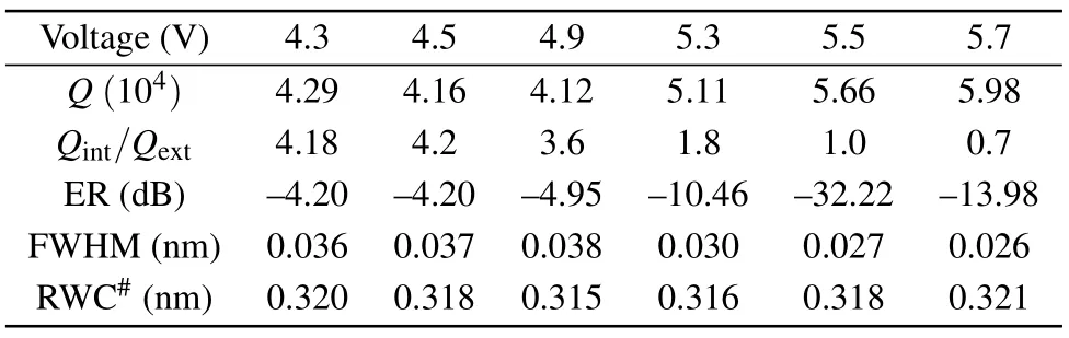
Table 1.The relationship between the voltage, Q, Qint/Qext, ER,FWHM,and RWC(‘#’indicates the results minus 1549).
Then we focus on how to gain large PGR from the microring at a fixed relative low pump power.Figure 3(a)shows the theoretical relationship between the PGR,Qint,p/Qext,pandQint,s(i)/Qs(i)according to Eq.(2).When theQvalue between the pump and the signal(idler)is independent,the maximum conversion efficiency point appears atQint,s(i)/Qext,s(i)=2 andQint,p/Qext,p=1.When theQvalue between the pump and the signal(idler)is the same and correlated,as shown by the black dotted line,the maximum conversion efficiency point appears atQint,s(i)/Qext,s(i)=Qint,p/Qext,p=4/3.TheQvalue between the pump and the signal (idler) of our working point is the same,that meansQint,s(i)/Qext,s(i)=Qint,p/Qext,p.To facilitate comparison with theoretical values,we define the normalized PGR as the measured value divided by the maximum value of all measured values.Fix the on-chip power at a suitable value,we explore the dependence of the normalized PGR of modes 5(1545.299 nm)and −5(1553.363 nm)with an on-chip pump power of 143µW.Figure 3(b)shows the results.It is clear to see that we gain the maximum PGR in the slight over-coupling region whenQint/Qext∈(1.4,1.8).The measured maximum coincidence count of pair(5,−5)is 56 Hz,and the pair generation rate(loss subtracted)is calculated to be 1.50 MHz/mW2.Besides, the black dashed line is the theoretical value whenQint/Qextof the signal, idler and pump are identical, and the maximum point appears whenQint/Qext≈4/3, which indicates that the experimental result is consistent with the theory basically.Therefore the PGR can be improved through the tunable extrinsic quality factor of the AMZI-coupled microring.This improved PGR value reaches a high level when compared to other published works.[32,33]It should be noted that this AMZI-coupled microring can ensure the high PGR by only one-run fabrication.It is of practical use since usually precise coupling efficiency of the microring requires precise control on the coupling gap between the waveguide and microring which needs multiple-run fabrication tests.
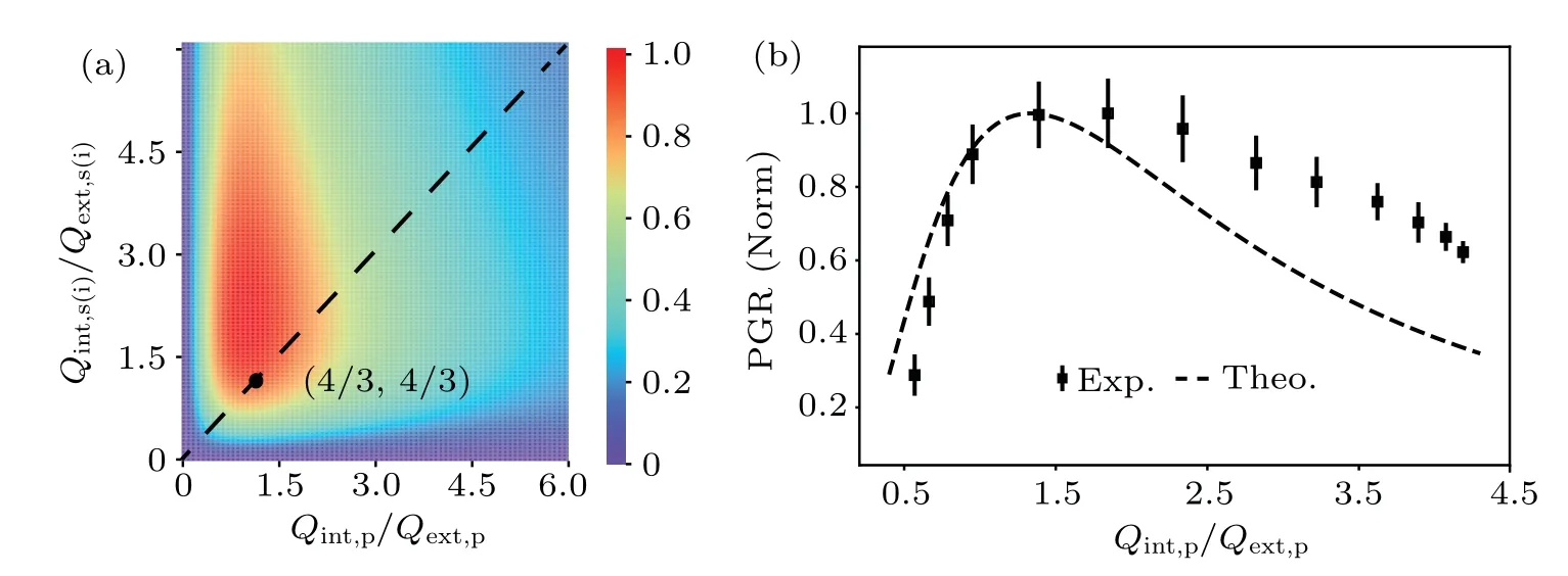
Fig.3.(a) The theoretical normalized PGR (color bar) changing with Qint,p/Qext,p and Qint,s(i)/Qext,s(i).The black dashed line is the result when assuming Qint,v/Qext,v are dependent,where v is signal,idler or pump.The maximum value appears when Qint,v/Qext,v =4/3.(b)The experimental PGR changing with Qint/Qext.The black dashed line is the theoretical curve of the PGR when Qint,v/Qext,v of the pump,signal and idler are identical.
We scan the input frequency from 1517 nm to 1582 nm and gain about 80 modes of the transmission spectrum.The on-chip coupling efficiency η refers to the ratio of the pump power before coupling to the chip through the waveguide grating array and coupling out of the chip.Figure 4(a)shows the normalized grating coupling efficiency when the wavelength changes from 1517 nm to 1582 nm(normalization means that all coupling efficiencies are divided by the maximum of them).The FSR is deduced to be 100 GHz which consists well with the theoretical design.The envelope of this transmission spectrum is mainly determined by the grating coupler which couples the pump laser into the chip.We set the on-chip power at 143µW and measure all the photon pairs of the combined frequency with the mode number varying from 1 to 30.Totally,there are 30×30=900 measurements.Moreover, for each measurement, we utilize 30 seconds to perform coincidences counting(CC),and we need 27000 seconds to measure the JSI.AtQint/Qext=1.8 which corresponds to a high PGR as illustrated in Fig.3(b),the JSI is measured and shown in Fig.4(b).Since the first two pairs of entangled photons close to the pump have a poor signal-to-noise ratio (CAR) which is shown by Fig.4(c),we choose 3(−3)to 30(−30)pairs for the Schmidt number calculation, and the JSI after removing the first two pairs is shown in Fig.4(d).It is clear to see that the diagonal elements dominate the complete coincidences, and this illustrates the good properties of the optical frequency comb we generated.The Schmidt number calculated from this raw data is 22.1.To restore the generation of on-chip photon pairs truly,we need to deduct the facet grating’s coupling efficiency with, where CC is the measuring coincidences counts,ηsand ηiare the coupling efficiencies of the signal photon and idler photon, respectively.The revised Schmidt number is 23.4 which corresponds to 547 dimensions Hilbert space in frequency freedom.The total coincidence count for all frequency pairs is 742 Hz and the pair generation rate(loss subtracted)is 19.9 MHz/mW2by summing up all the frequency pairs.
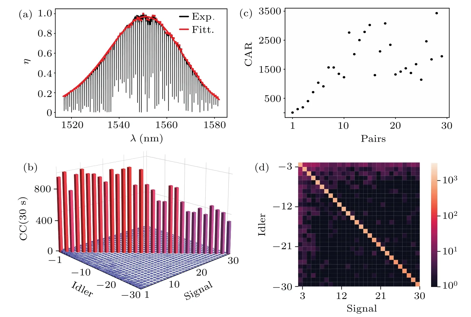
Fig.4.(a)The experimental results of the normalized coupling efficiency when the wavelength varies from 1517 nm to 1582 nm,and the red line is the fitting result of a Gaussian function.(b)The coincidence for 30 pairs of a total of 900 measurements.(c)The CAR of 30 photon pairs.(d)The measured JSI from mode 3(−3)to 30(−30)at the coupling point of Qint/Qext=1.8.The color bar is CC in logarithmic coordinates.
3.Discussion and conclusion
In conclusion, we demonstrated a 100 GHz spacing biphoton frequency comb that matched the ITU frequency grid and obtained at least 23.4-dimension frequency entanglement,which corresponds to 547 dimension available frequency resources in Hilbert space.This high-dimensional frequency entanglement is achieved with a high pair generation rate of 19.9 MHz/mW2at a relatively low on-chip pump power of 143µW,which is ensured through the accurate coupling condition of microring by using AMZI as the coupler.This structure design can also be extended to other materials such as SiN,[18]lithium niobate(LN),[34]etc.Actually, if we replace the grating coupler with an end coupler,move the pump light to a more suitable wavelength range, or design the dispersion of the waveguide,[35]we can measure higher dimension BFC.This type of low-power consumption and high-quality quantum frequency comb can be high-density designed on the quantum photonic chip for further applications of large-scale quantum computation and quantum communications.
Acknowledgements
Project supported by the National Basic Research Program of China (Grant Nos.2019YFA0308700 and 2017YFA0303700),the National Natural Science Foundation of China(Grant Nos.61632021 and 11690031),and the Open Funds from the State Key Laboratory of High Performance Computing of China (HPCL, National University of Defense Technology).
猜你喜欢
科学家(2022年5期)2022-05-13
中国水运(2022年4期)2022-04-27
科学家(2022年3期)2022-04-11
小读者(2021年4期)2021-06-11
海峡姐妹(2019年11期)2019-12-23
作文大王·低年级(2019年2期)2019-01-23
作文大王·低年级(2018年9期)2018-10-24
艺术评论(2017年8期)2017-10-16
金山(2017年9期)2017-09-23
文史春秋(2016年6期)2016-12-01
- Chinese Physics B的其它文章
- High sensitivity plasmonic temperature sensor based on a side-polished photonic crystal fiber
- Digital synthesis of programmable photonic integrated circuits
- Non-Rayleigh photon statistics of superbunching pseudothermal light
- Refractive index sensing of double Fano resonance excited by nano-cube array coupled with multilayer all-dielectric film
- A novel polarization converter based on the band-stop frequency selective surface
- Effects of pulse energy ratios on plasma characteristics of dual-pulse fiber-optic laser-induced breakdown spectroscopy