Calibration of single optical wedge compensation test system error by computer generation hologram
2022-03-08 03:47CAIZhihuaWANGXiaokunHUHaixiangCHENGQiangWANGRuoqiuZHANGHaidong
中国光学 2022年1期
CAI Zhi-hua,WANG Xiao-kun ,HU Hai-xiang ,CHENG Qiang,WANG Ruo-qiu,ZHANG Hai-dong
(1. Changchun Institute of Optics, Fine Mechanics and Physics,Chinese Academy of Sciences, Changchun 130033, China;2. University of Chinese Academy of Sciences, Beijing 100049, China)
Abstract: As a testing method for large convex aspheric surface, the single optical wedge compensation test has good applicability, robustness and flexibility. However, various errors are coupled with one another during the test process and these errors are difficult to decouple. This affects the accuracy and reliability of the tests. To address this, a method is developed to calibrate the system error of single optical wedge test paths using a Computer Generation Hologram (CGH). We first analysed the source of system error in the optical path of a single optical wedge compensation test as well as the feasibility of using CGH for the calibration of an optical wedge compensation test system. In combination with engineering examples, a CGH was designed for optical wedge compensators with a diameter of 150 mm. Based on the analysis results, the calibration accuracy of the CGH was 1.98 nm RMS, and after calibration the test accuracy of single wedge compensation was 3.43 nm RMS, thereby meeting the high-precision test requirements of large convex aspheric mirrors. This shows that CGH can accurately calibrate the pose of single optical wedge compensators and the test system errors of optical paths. Thus we address the problems affecting error decoupling in test optical paths, and improve the accuracy and reliability of the single optical wedge compensation method. Meanwhile, using CGH calibration, the system errors of the test optical paths, Tap#2 and Tap#3, were 0.023 and 0.011 λ RMS, respectively.
Key words: computer generation hologram; optical test; diffraction; optical wedge
1 Introduction
High-precision metrology of large aspheric surfaces, especially large convex aspheric mirrors, has always been a challenge in optical measurement[1-2].A method commonly used for effective testing large convex aspheric mirrors is the non-null test method[3-4]. Compared with traditional non-null compensators, single optical wedges have unique advantages[5-6]. Firstly, an optical wedge can produce astigmatism and coma that can be used to compensate for the main aberrations of the off-axis part of large convex aspheric surfaces. Secondly, optical wedges are simple to manufacture, do not require high-quality glass materials, and do not require coating on their surface. Thirdly, it can be verified that the single optical wedge compensation stitching method has good applicability, robustness and flexibility when testing large convex aspheric mirrors.Moreover, the full-aperture surface test accuracy of this method can reach 3.8 nmRMS, which meets the high-precision test requirements of large convex aspheric surfaces[7].
However, the optical wedge compensation test is difficult to calibrate in practice. This is mainly because the beam is speckled after passing through the optical wedge, complicating the isolation and correction of systematic errors in the optical path using traditional methods. The main difficulty is the decoupling of the main error. Due to this, improving the calibration accuracy of single optical wedge compensation systems is key to improving the test reliability[8].
Computer Generation Hologram (CGH) overcome the difficulty that optical holograms have reference entities. CGH can generate any form of wavefront, so it can be used to simulate the reflected wavefront of an ideal aspheric surface to calibrate the optical wedge compensator pose and eliminate systematic errors[9-10]. CGH-based measurements were proposed in the 1970s and have gradually become a mature, high-precision optical test technology. For example, Burge[11]used CGH to successfully test super-large aspheric surfaces. Zhou et al.[12]divided the error induced by CGH used in the laboratory in two parts, distortion and manufacturing errors.
Zhao et al.[13]combined the work of Zhou et al.to calibrate and separate CGH substrate error. They used this method to increase CGH accuracy to 6 nm.Burge[14]used a reflective CGH to calibrate the compensator to prevent immense economic losses caused by the compensator error. In China, CGH has usually been employed to test the surface of large aspheric optical elements and calibrate null compensators[15-16]. For example, Zhu et al. calibrated a null-lens compensator using a tilted computer holographic plate[17], and Chen et al. calibrated a zero compensator of a Φ850 mm F/2 parabolic primary mirror using CGH[18]. The abovementioned examples show that CGH can be used to calibrate optical wedge compensators.
To solve the calibration problem of optical wedge compensators, a reflective CGH calibration method for an optical wedge compensator is proposed. In Sect.2, we first explains the source of error in single optical wedge compensation test optical path and analyzes the feasibility of using CGH calibration in a single optical wedge test system. In Sect.3, the design scheme of the CGH is introduced in detail, the source of CGH error is analysed, the calibration accuracy of the CGH is provided, and the test accuracy of the full-aperture surface shape after CGH calibration is analysed. In Sect.4, the calibration of the single wedge compensation test system error using the CGH is described.
2 Feasibility analysis of using CGH for calibrating single optical wedge compensation test system
2.1 Error source of the single optical wedge compensation test system
As shown in Fig. 1, the test result obtained by the interferometer is the superposition of the test wavefronts. This can be expressed asW=Wa+WN+wm, whereWNis a non-null error that can be obtained by simulations.Wa=w2−w1=WTS⊕WOW(⊕is the coupling symbol), whereWTSis the system error of the transmission sphere, andWOWis the systematic error introduced by a single optical wedge due to manufacturing and adjustment. When testing the subaperture of the same ring,Wacan be considered as the system error. After calibration,Wacan be eliminated, thereby enabling the realization of error decoupling and obtaining the aspheric surface error,wm=w4−w3=W−Wa−WN.
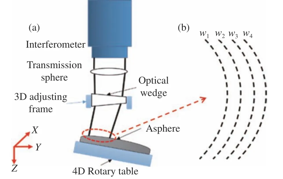
Fig. 1 (a) Single optical wedge test optical path. (b)Schematic of the test wavefront. w1, w2, w3, w4 are theoretical incident wavefront, actual incident wavefront, theoretical aspheric surface and actual aspheric surface, respectively.
Based on engineering examples, a test scheme for single optical wedge compensation stitching is designed for large convex aspheric mirrors with a diameter of 425 mm[7]. The subaperture planning and optical wedge design parameters are listed in Table 1. The optical wedge manufacturing error, the transmission sphere system error, and the non-null error of the test optical path are shown in Fig. 2(Color online). To verify the feasibility of using CGH for calibrating the system error of a single optical wedge test path, a reflective CGH is designed for the single wedge compensator used in Tap#2.

Fig. 2 (a) Surface shape of the optical wedge A. (b) Surface shape of optical wedge B. (c) Transmitted wave aberration.(d) Transmission sphere system error. (e) Tap#1 non-null error. (f) Tap#2 non-null error. (g) Tap#3 non-null error.

Tab. 1 Basic parameters
2.2 CGH calibration of the single optical wedge test path
The CGH calibrated single optical wedge compensation test optical path as shown in Fig. 3. The transmission sphere converts the parallel light emitted by the interferometer into a convergent spherical wave. This spherical wave is then transformed into an aspheric wave when the beam passes through the wedge compensator. The test mirror is replaced with the CGH. The light passing through the compensator illuminates the CGH and is completely reflected, returning to the interferometer along the original path. At this point, the CGH diffraction pattern is completely matched with the aspherical wave, forming a common test optical path, so that the pose and system errors of the optical wedge compensator can be calibrated out.

Fig. 3 Calibration of the single optical wedge test path
2.3 Sensitivity analysis of single optical wedge compensation test adjustment system
Combining the requirements of convex aspheric surface shape accuracy test (greater than 1/50λ RMS), and taking the wavefront change of 0.001λ as an example, the feasibility of CGH calibration of the optical wedge pose is analysed. The results are shown in Table 2. It can be seen that the accuracy of the CGH in calibrating the optical wedge pose is higher than the accuracy required for testing the optical wedge pose in the optical path. Therefore, after the single optical wedge compensator is calibrated,its pose accuracy can meet the measurement requirements.

Tab. 2 Adjustment tolerance analysis of the optical wedge compensator
2.4 CGH fringe contrast analysis
Based on typical CGH diffraction efficiency,the diffraction efficiency of the CGH is analysed.The calculation formula is shown in Eq (1)[19].

WhereT0andT1are the amplitude transmittance of the bright and dark fringes, respectively,ψetchis the phase difference,qdenotes the duty cycle, andmis the diffraction order.T0=0,T1=1,q=1/2,ψetch=0.
For the amplitude in the CGH, the diffracted light intensity is 25% for the 0thorder, 10.132% for the ±1storder, 1.126% for the ±3rdorder and 0.405%for the ±5thorder. For the phase of the CGH, there is theoretically no even diffraction order. The diffracted light intensity for the ±1storder is 40.528%,4.503% for the ±3rdorder and 1.621% for the ±5thorder.
Assuming reference intensityI1=0.04, outgoing light intensity

interference light intensity

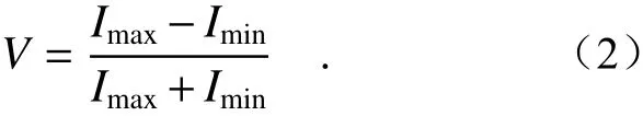
and fringe contrast:
The fringe contrast of each diffraction order of the CGH is obtained. The results are presented in Table 3.
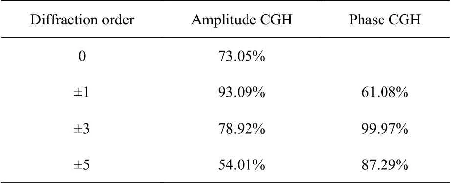
Tab. 3 CGH fringe contrast
It can be seen that both the amplitude and phase CGH design schemes meet the fringe contrast requirements. However, the amplitude CGH has a simpler process, the lowest error among alternatives and a higher accuracy. Therefore, we adopt the amplitude type CGH in this work.
3 CGH design plan
As shown in Fig.3, the CGH is used to replace the test mirror to calibrate the single optical wedge test optical path. Therefore, as shown in Fig. 4(Color online), only the main area and alignment area need to be designed when designing the CGH.

Fig. 4 Structure of the CGH
3.1 Design of the main area
The CGH main area is to calibrate the pose and system error of the optical wedge test system, which uses +1 as the main diffraction order. The design residual is shown in Fig. 5(a). As can be seen, the residual RMS is 1.77×10⁻⁵λ, thereby meeting the design requirements. The diffraction energy level distribution of the multi-configuration is shown in Fig. 5(b). The distance between the +1st and 0th order diffraction spots is greater than 200 μm, meeting the requirement that the main diffraction order must be completely separated from the others. The diffraction pattern and setting parameter are shown in Fig.5(c) and Fig.5(b). The stripe line width is calculated using empirical equation (3):

Fig. 5 Main area of the CGH. (a) Design residual; (b) diffraction order energy level distribution; (c) diffraction pattern; (d)surface phase setting parameters

whereDapertureis the aperture of the CGH′s main area,ncfis equal to the value of the contour format andNrepresents the number of stripes. In this case,Daperture=119.52 mm,ncf=1000,N=19 and the stripe line width of the main arealmain=3 μm. This value meets the requirements of conventional CGH processing technology and can be processed and produced by laser direct writing and ion beam etching.
3.2 Alignment area design
The CGH alignment area is used to align the relative position between the interferometer and the CGH, which used +3 as the main diffraction order.Fig 6 shows that the CGH alignment area appears as the green crescent-shaped structure in Fig. 4 due to the deflection introduced by the optical wedge.

Fig. 6 Schematic of the single optical wedge deflection light path
The design residual is depicted in Fig. 7(a)(Color online). The residual RMS is 8.00×10⁻⁶λ,thereby meeting the design requirements. The diffraction energy level distribution of the multi-configuration is depicted in Fig. 7(b) (Color online).The main diffraction order is completely separated from the other diffraction orders (Fig. 7(c)), eliminating the influence of the remaining diffraction orders on the main one. The width of the stripe line of the alignment area is obtained as 8 μm using Eq. (3).This also satisfies the requirements of conventional CGH processing technology and thus can be processed and produced by laser direct writing and ion beam etching.

Fig. 7 Alignment area. (a) Design residual; (b) diffraction order energy level distribution; (c) diffraction pattern
3.3 CGH error analysis
An amplitude-type CGH is used in this study.When calculating CGH error sources, the main considerations are design residuals, coding errors, substrate errors and characteristic distortion[20]. The CGH design residual is 1.77×10⁻⁵λ, the actual coding error is 9.00×10⁻⁴λ, and the substrate error test result is 3×10⁻³λ, as shown in Fig. 8 (Color online).When creating the CGH, the CGH wavefront error caused by the positioning error of the laser direct writing instrument is the characterization distortion,of 1.57×10⁻⁴λ. As presented in Table 4, the analysis of the abovementioned error resulted in a CGH calibration accuracy of 3.10×10⁻³λRMS (1.98 nm).

Fig. 8 Substrate error
The test accuracy of single optical wedge compensation under CGH calibration is also analysed.The random noise in Table 5 can be obtained by averaging multiple measurements. Fig. 9 (Color online) shows the test results of a convex spherical surface with a diameter of 197 mm using the stitching algorithm in this paper. From Fig. 9(d), the stitching algorithm can be obtained as 0.002λRMS(1.26 nm). As presented in Table 5, the analysis showed that the accuracy of the single optical wedge compensation test after CGH calibration is 3.43 nm RMS, thereby meeting the requirements of calibrating large convex aspheric surfaces. The results showed that CGH can be used to calibrate the pose and system error of a single optical wedge compensator and to improve the accuracy and reliability of the single optical wedge compensation test method.

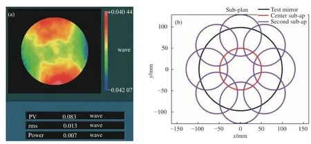
Fig. 9 Convex spherical stitching test result (D = 197 mm) (a) Actual full-aperture surface; (b) sub-plane; (c) stitching test result; (d) the residual difference between the stitching test result and the full-aperture surface result

Tab. 4 CGH error

Tab. 5 Single optical wedge compensation test accuracy after CGH calibration (nm)
4 CGH calibration test system′s error
After analysis, the CGH is used to calibrate the actual single optical wedge compensation test optical path. The test optical path is depicted in Fig. 10. Firstly, the position of CGH on the turntable was determinated. The mark in theXdirection on the CGH was parallel to theXdirection of the turntable, and the mark in theYdirection on the CGH was coincide with theYaxis of the turntable.Then, the CGH along theYaxis was moved to the design position.

Fig. 10 (a) Calibration optical path diagram of optical wedge compensator. (b) CGH and interferometer aligned on the optical path. (c) Insertion of the optical wedge compensator
After the CGH position was determined, the CGH alignment area was used to align the position between the interferometer and CGH, as depicted in Fig. 9(b). The alignment area test results are shown in Fig. 10(a) and Fig. 10(c). Eq(4) is used to calculate the defocusεzbetween the CGH and interferometer on theZ-axis to determine whether the alignment between the interferometer and the CGH is complete. Here,F#=13 and ΔWdefocusrepresent the Peak-to-Valley(PV) in the test result. Taking Fig. 10(a)as an example, the defocusεzbetween the focal point of the CGH and the focal point of the interferometer is obtained asεz=0.056 mm. This distance meets the adjustment requirement of the test mirror;therefore, the alignment between the interferometer and the CGH was complete.

After alignment, we calibrated the single wedge compensator, as shown in Fig. 11 (Color online). The calibration error results of Tap#2 (Fig.11(b)), and Tap#2 (Fig. 11(d)) are 0.023λRMS and 0.011λRMS, respectively. When the single optical wedge stitching is used to test the full-aperture surface, the system error obtained by calibration can be eliminated. Therefore, the accuracy and credibility of the single optical wedge compensation test is improved.

Fig. 11 Calibration results for the test path system error. (a) CGH alignment result by Tap#2. (b) Test path system error by Tap#2. (c) CGH alignment result by Tap#3. (d) Test path system error by Tap#3
5 Conclusion
A method that uses reflective CGH calibration for a single optical wedge error test compensation system is proposed. The method decouples the errors in the test results of single optical wedge compensation. The feasibility of the method is verified through analysis of the CGH principle, fringe contrast, and the sensitivity of the single wedge compensator in testing and adjusting the optical path.
In addition, a reflective CGH calibration experiment is designed for the single optical wedge test optical path to test large convex aspheric mirrors with a diameter of 425 mm. The CGH calibration accuracy is 1.98 nmRMS. After CGH calibration,the test accuracy of the full surface of single wedge compensation is 3.43 nmRMS, thereby meeting the calibration requirements of single optical test optical paths for system errors. We also obtained systematic errors at two Tap of 0.023λ and 0.011λ after CGH calibration.
The analysis and experimental results show that the reflective CGH calibration method can accurately calibrate the single optical wedge compensation test path, including both the system error and pose, thereby improving the test accuracy and credibility of the single optical wedge compensation method.