
An electromagnetic wave attenuation superposition structure for thin-layer plasma
2022-03-10 03:50WenyuanZHANG张文远HaojunXU徐浩军BinbinPEI裴彬彬XiaolongWEI魏小龙PeiFENG冯佩andLinZHANG张琳
Plasma Science and Technology 2022年2期
Wenyuan ZHANG(张文远),Haojun XU(徐浩军),Binbin PEI(裴彬彬),2,Xiaolong WEI(魏小龙),Pei FENG(冯佩) and Lin ZHANG(张琳)
1 Science and Technology on Plasma Dynamics Laboratory,Air Force Engineering University,Xi’an 710038,People’s Republic of China
2 School of Electronic Engineering,Xidian University,Xi’an 710126,People’s Republic of China
Abstract This work proposes a new plasma super-phase gradient metasurfaces(PS-PGMs)structure,owing to the limitations of the thin-layer plasma for electromagnetic wave attenuation.Based on the cross-shaped surface unit configuration,we have designed the X-band absorbing structure through the dispersion control method.By setting up the Drude dispersion model in the computer simulation technology,the designed phase gradient metasurfaces structure is superposed over the plasma,and the PS-PGMs structure is constructed.The electromagnetic scattering characteristics of the new structure have been simulated,and the reflectance measurement has been carried out to verify the absorbing effect.The results demonstrate that the attenuation effect of the new structure is superior to that of the pure plasma structure,which invokes an improved attenuation effect from the thin layer plasma,thus enhancing the feasibility of applying the plasma stealth technology to the local stealth of the strong scattering part of a combat aircraft.
Keywords:electromagnetic wave attenuation,thin-layer plasma,superimposed structure,plasma stealth technology
1.Introduction
Plasma stealth is a novel concept in stealth technology.It has the advantage of real-time adjustment of the absorption band without affecting the aerodynamic performance of the aircraft or the bandwidth of the absorption wave[1-3].At the macro level,when electromagnetic waves interact with the plasma,multiple propagation mechanisms such as reflection,refraction,and attenuation will occur.Whereas,at the micro level,the response of free electrons in the plasma to the electric field component of the electromagnetic wave will alter the propagation characteristics.Owing to the plasma attenuation characteristics of the electromagnetic waves,the application of plasma stealth technology can effectively attenuate the radar cross section of the target.However,the attenuation effect has a strong relationship with the characteristic parameter distribution and the thickness of the plasma.Generally,a more ideal absorption effect is achieved exclusively for the electron density of a certain order of magnitude,for which the thickness of the plasma exceeds 10 cm[4-8].However,excessive thickness will increase the weight and volume of the discharge system,and cannot meet the lightweight requirements of the modern fighter aircrafts.Henceforth,certain scholars have proposed a multilayer composite electromagnetic attenuation structure,to solve the constraint of plasma thickness[9,10].Although the application of the composite structure can reduce the thickness of the plasma,a multilayer composite structure needs to be superimposed to achieve the expected attenuation effect,which results in large overall thickness[11].Furthermore,the attenuation frequency band of the composite structure is a fixed value,and the frequency band parameters are difficult to adjust since the adjustment range is limited[12].Therefore,this structure will fail,while dealing with the plasma stealth for multi-band broadband radars.The multilayer composite electromagnetic attenuation structure is often a longitudinal superposition of several absorbing materials,and the material can only absorb a part of the incident electromagnetic waves,and hence,cannot fundamentally promote and improve the absorption effect of the plasma itself.To address these problems,we propose a new stealth structure of plasma super-phase gradient metasurfaces(PS-PGMs)to remedy the limitation of the thickness of plasma stealth technology.
Phase gradient metasurfaces is a two-dimensional plane of structural units arranged with varying geometric parameters in a certain order,based on the phase mutation and polarization control characteristics of the metamaterial structure.In the applications of stealth technology,by introducing the phase mutation of the wavelength scale and rational arrangement of the unit structure,abnormal reflection and refraction can be generated,thereby attenuating the electromagnetic wave energy to achieve the stealth requirement[13-16].When the phase gradient metasurfaces and the plasma are superimposed,owing to the abnormal reflection effect of the phase gradient metasurfaces on electromagnetic waves,the lateral propagation distance of the electromagnetic waves can be extended.To achieve a better absorbing effect,the propagation distance of the electromagnetic waves in the plasma will increase.Increasing the propagation distance of the electromagnetic waves in the plasma can achieve a better attenuation effect in the thin plasma structure,thereby reducing the thickness of the plasma.Furthermore,it solves the limitation of the thickness of the plasma stealth and the multilayer composite structure stealth.The electromagnetic wave reflection direction is according to the active control characteristics of the phase gradient metasurfaces.This work proposes a new type of attenuation structure for PS-PGMs.Plasma is employed as the attenuation medium for the electromagnetic waves.By adjusting the characteristic parameters of the plasma,the attenuation frequency band of the electromagnetic waves can be altered.Simultaneously,the gradient metasurfaces are utilized to adjust the electromagnetic wave to change the reflection direction of the incident electromagnetic wave,and to increase the propagation distance of the electromagnetic wave in the plasma,thereby remedying the effective attenuation of the electromagnetic wave in the thin-layer plasma structure.
2.Design of phase gradient metasurfaces
In this section,the theory of PGMs design will be introduced,and the PGMs structure obtained will be simulated and experimentally studied,as a prerequisite for the design of the superposition structure.
2.1.The theory of PGMs design
From the above expression,we get the abnormal reflection of electromagnetic waves that can be achieved for a reasonably designed phase gradient of the periodic structure.
2.2.Characteristics of PGMs
The cross-shaped structure has the advantages of a simple structure and easy adjustment of the geometric parameters.It is currently the most extensively used and most well-known basic unit structure of meta-materials[18,19].In this work,the design method in[20]has been employed and adapted to the needs of this work,and PGMs with a cross shape as the basic unit have been designed.The basic unit structure is shown in figure 2(a).Accordingly,the intermediate dielectric plate is FR4(εr=4.3,tanδ=0.025),the thickness ist,the side length isl,and the width of the cross-shaped metal plate isa.
Figure 2(c)shows the structural diagram of the metasurfaces after the unit structure is composed.At 10 GHz,the metasurfaces are designed with the above-mentioned structural geometric parameters such that the phase difference between the adjacent structural units in thex-direction andydirection is Δφ=60°.Therefore,the modulus of the phase gradient is1000π/75 rad m-1.The abnormal reflection angle of the metasurface is 58°,as calculated from equation(9).
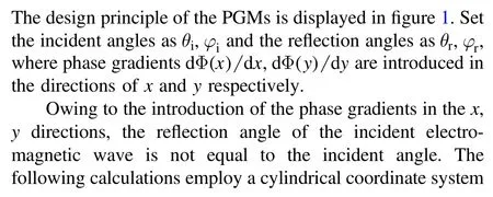
Figure 1.Schematic diagram of PGMs design principle.
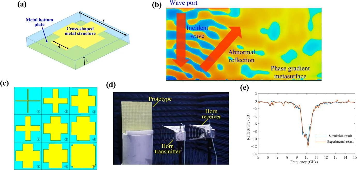
Figure 2.(a)Basic unit structure of the PGMs,(b)energy flow simulation diagram of PGMs,(c)schematic diagram of PGMs,(d)experimental device for reflectance test,(e)experimental results and simulation results of the reflectance test.
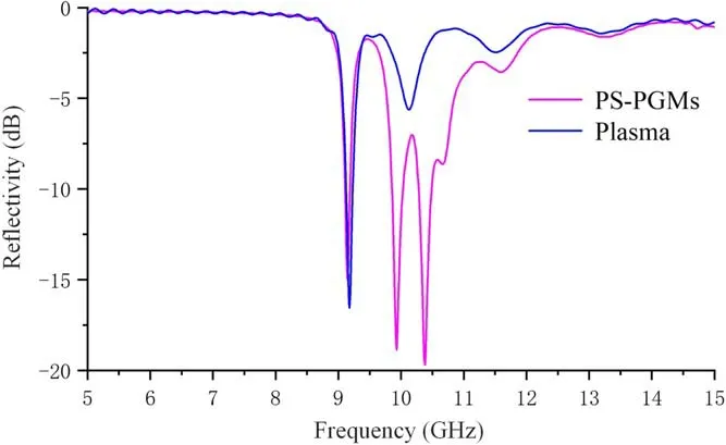
Figure 3.Comparison of the simulation of the reflectivity between PS-PGMs and the plasma structure for a pressure of 10 Pa,thickness of 6 cm,and power of 600 W.
To verify the designed PGMs structure,the frequency domain solver of computer simulation technology(CST)has been employed to solve the reflectance and energy flow diagram of the metasurfaces.Further,the reflectance test experiment has been carried out.The experimental device is shown in figure 2(d).According to figure 2(b),the designed PGMs can produce an abnormal reflection with a reflection angle of about 58° to the perpendicularly incident electromagnetic wave.The experimental and simulation results of the reflectance test are shown in figure 2(e).The experimental test and simulation results are basically consistent.The designed PGMs structure can effectively reduce the reflectivity when the electromagnetic waves are incident perpendicularly.In the vicinity of 10 GHz,the reflectivity can exceed 10 dB.
3.Simulation research
To verify the electromagnetic attenuation characteristics of PS-PGMs,a geometric model of PS-PGMs has been established in the CST simulation platform,and its attenuation characteristics are solved by simulation.The method of setting the characteristic parameters is used to establish a plasma layered model in CST to simulate plasma parameters more accurately.The set electron density is the plasma distribution,for the case of a single peak.In the Drude model in CST,the plasma frequencyωpand collision frequencyνmare substituted.In the control model,the bottom plate is set as a metal plate.
Figure 3 shows the comparison of the simulation of the reflectivity between PS-PGMs and the plasma structure for a pressure of 10 Pa,thickness of 6 cm,and power of 600 W.It can be seen from the figure that the attenuation effect after the superposition of the PGMs structure is superior to that before the superposition.In the X-band,the attenuation effect of PSPGMs is significantly enhanced,and the maximum attenuation value has increased from-15 to-20 dB.Compared with the plasma structure,the attenuation frequency band is wider,and the two effective attenuation frequency bands are added between 10.0 and 10.5 GHz.Hence,the proposed PS-PGMs structure can enhance the electromagnetic wave attenuation effect.
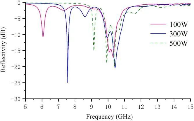
Figure 4.Reflectivity of PS-PGMs under different powers at 10 Pa pressure and 6 cm thickness.
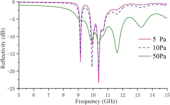
Figure 5.Reflectivity of PS-PGMs under different air pressures at 500 W power and 6 cm thickness.
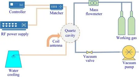
Figure 6.Schematic diagram of electromagnetic scattering characteristics test system.
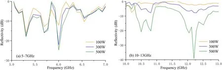
Figure 7.Reflectivity test results when the plasma thickness is 3 cm.
The attenuation characteristics of PS-PGMs under different power at 10 Pa and 6 cm thickness are displayed in figure 4.Accordingly,the working frequency range is below that of the metasurfaces,and the effective attenuation band gradually shifts to the high-frequency direction with the increase of power,thus enhancing the attenuation effect.Thus,the attenuation in this frequency band is primarily produced by the plasma,and the plasma electron density gradually increases with the increasing power.On one hand,the dominant effect of plasma collisional absorption becomes more pronounced due to the increase in electron density.On the other hand,the increase in electron density leads to a consequent increase in plasma frequency and a shift in the plasma resonance absorption frequency towards a higher frequency.As a result of the combined effect of the above two effects,the plasma absorption effect shifts towards a higher frequency with increasing power,and the attenuation effect is significantly enhanced.For a power of 100 W,the first attenuation band is around 6 GHz,and the reflectivity can reach -10 dB.When the power is increased to 300 W,the first attenuation band appears around 7.5 GHz and the reflectivity drops to -25 dB.When the power steadily increases to 500 W,the first attenuation band shifts to 9 GHz,though the attenuation peak is reduced.In the working frequency range of the metasurfaces,as the power increases,the attenuation frequency band remains unchanged and concentrated between 10 and 11 GHz.For a low power,there is only one attenuation frequency band.With the increase of power,the attenuation frequency band increases.When the power is increased to 500 W,there are three effective attenuation frequency bands,and the attenuation peak value is proximate to -20 dB.
The attenuation effect of PS-PGMs under different air pressures at a thickness of 6 cm and power of 500 W,is shown in figure 5.We find from the simulation results that the attenuation effect for the pressure values of 5 Pa and 10 Pa,is basically the same.However,when the air pressure rises,the attenuation frequency bandwidth will gradually increase.When the air pressure rises to 50 Pa,the entire frequency band acquires attenuation characteristics despite the reduction in the attenuation peak.The attenuation bandwidth is markedly widened,particularly under high pressure.It is believed that under the plasma condition,the plasma will appear extremely inhomogeneous at high pressure,and the attenuation effect will be reduced.The attenuation effect of PS-PGMs has been enhanced owing to the following reasons,viz,the high air pressure that leads to an increased plasma inhomogeneity,the abnormal reflection of the electromagnetic waves caused by the PGMs,the significant increase of the propagation distance of the electromagnetic waves in the lateral direction,and the multiple reflections and refractions of the electromagnetic waves.Hence the attenuation effect significantly improves.
4.Experimental results and data analysis
4.1.Experimental study on electromagnetic scattering characteristics of inductively coupled plasma
In this section,the experiment of electromagnetic scattering characteristics of the ICP structure is reported.The schematic diagram of the experimental system is shown in figure 6.The chamber structure employed in the test consists of 3 cm and 6 cm vacuum quartz chambers.
The reflectivity test results for a plasma thickness 3 cm are shown in figure 7.While processing the results,only the test results of the effective attenuation frequency band are given to observe the effective attenuation effect in the attenuation frequency band in detail,and the frequency band without attenuation effect is omitted.Figure 7(a)displays the test results of 5-7 GHz.The attenuation effect in this frequency band increases with the increase of the discharge power,though the increase effect is not marked.When the power is increased from 300 to 500 W,the attenuation effect is almost unchanged.It indicates that the attenuation effect is almost unaffected by power in the low-frequency range.Figure 7(b)shows the test results of 10-13 GHz.Accordingly,the attenuation effect of this frequency band is completely different from that of the low-frequency band.When the discharge power is 100 W,there is negligible attenuation effect in this frequency band.For a power increased up to 300 W,the attenuation effect is unsatisfactory.When the power is increased to 500 W,the attenuation effect is quickly enhanced.The attenuations in both the 10.3-10.9 GHz and 11.6-12.7 GHz bands exceed -10 dB,and the reflectivity at 12.2 GHz reaches -40 dB.This demonstrates that the attenuation frequency of the plasma at high frequency is significantly affected by power.With the increase of power,the attenuation effect at high frequency emerges from nothing,and the attenuation effect is very ideal.
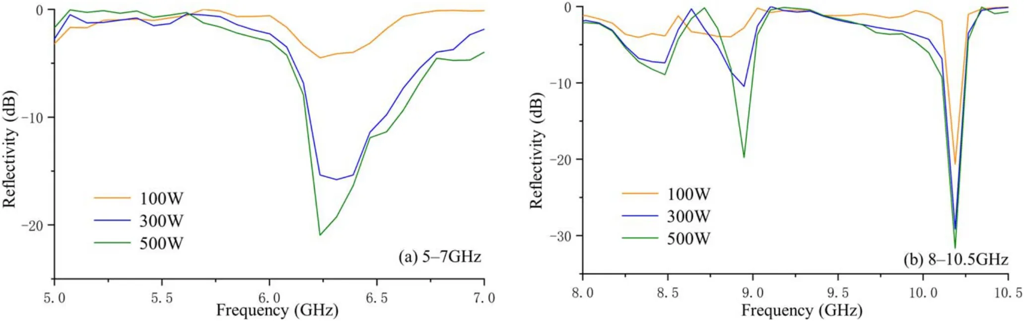
Figure 8.Reflectivity test results when the plasma thickness is 6 cm.
The results of the reflectivity test for a plasma thickness of 6 cm are shown in figure 8.Figure 8(a)shows the test results of 5-7 GHz,and accordingly,the attenuation effect is mainly concentrated between 6 and 7 GHz.The attenuation effect has significantly improved with the increase of the discharge power.When the power exceeds 300 W,the reflectivity goes above -10 dB.By comparing the attenuation effect for the cavity thickness of 3 cm,and for an increase of the thickness of the cavity,the effective attenuation frequency band shifts to high frequency,and the attenuation effect is increasingly affected by the power.Figure 8(b)shows the test results of 8-10.5 GHz.The only one effective attenuation frequency band for a low power,in this frequency range,is concentrated near the 10.2 GHz frequency point,and the attenuation effect at this frequency band does not change much with power.When the power increases,there will be a second effective attenuation band at 8.9 GHz.Further,the reflectivity reaches -20 dB for an increase of power to 500 W.
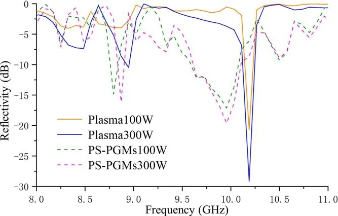
Figure 9.Comparison chart of reflectivity test results between plasma and PS-PGMs for a pressure of 10 Pa,thickness of 6 cm,and powers of 100 W and 300 W.
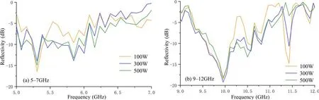
Figure 10.Reflectivity test results of PS-PGMs with the plasma thickness of 3 cm.
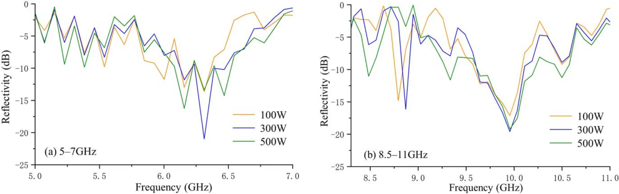
Figure 11.Reflectivity test result of PS-PGMs when the plasma thickness is 6 cm.
Combining the above analysis,we conclude that in a pure plasma structure,the attenuation effect will decrease as the plasma thickness decreases.Therefore,this work proposes the PS-PGMs structure,which utilizes the abnormal reflection characteristics of the PGMs to remedy the insufficiency of the poor electromagnetic attenuation effect of the thin-layer plasma.
4.2.Experimental study on the electromagnetic scattering characteristics of PS-PGMs
To verify the attenuation simulation results of PS-PGMs,the experiment on the electromagnetic scattering characteristics of the PS-PGMs structure is reported in this section.The test device is the same as the reflectance test experiment.In the experiment,the PGMs has been placed at the bottom of the plasma chamber,whereas the PGMs has been replaced by a metal plate in the control experiment.
The results from the measurement for a chamber thickness of 6 cm and air pressure of 10 Pa,are shown in figure 9.The solid line is the test result before superimposing the PGMs.Generally,the attenuation effect has improved with the increase of power.When the discharge power is increased,a new effective attenuation section will appear in the low frequency range.Further,the attenuation peak at high frequencies will increase with the increase of power.However,the attenuation frequency band is narrow overall,and the attenuation effect is still not ideal.When the power is 100 W,compared with the attenuation effect of PS-PGMs,the attenuation effect of the plasma is not ideal for low power.There is hardly any attenuation effect at the low frequency band,and the attenuation band near 10.2 GHz is very narrow.The attenuation effect of PS-PGMs has appreciably improved.An attenuation frequency band appears at the 8.6 GHz frequency point,specifically near the effective frequency of the PGMs,and the reflectivity reaches -17 dB.The attenuation frequency band has attained significant attenuation effect between 9.5 and 10.1 GHz.When the power is increased to 300 W,the attenuation effect of the un-superposed structure reaches -10 dB in the low frequency band and -28 dB at 10.2 GHz respectively,though the attenuation band is narrow and the attenuation effect is not ideal.The reflectivity of PSPGMs in the low frequency range has reached -15 dB,specifically between 9.5 and 10.1 GHz,and the reflectivity has been reduced to -20 dB,besides improving the attenuation effect.Henceforth,for a discharge power,the absorbing effect of the plasma is relatively weak.The decrease in the reflectivity is primarily caused by the abnormal reflection of the PGMs.The attenuation effect is unsatisfactory when there is no superimposed structure.This owes to the plasma generated in the thin-layer chamber having a significant inhomogeneity,and the propagation distance of the reflected wave in the chamber being short,thus resulting in an unsatisfactory attenuation effect.After being superimposed with PGMs,the lateral propagation distance of the reflected electromagnetic wave increases,which improves the absorbing effect to a certain extent.
The results from the measurement of PS-PGMs for an air pressure of 10 Pa and chamber thickness of 3 cm are shown in figure 10.The attenuation effect of PS-PGMs in the range of 5-7 GHz does not vary significantly with the power,since the attenuation effect of this frequency band is mainly produced by plasma.By comparing the attenuation effect diagram for this frequency band of the plasma,we find that the attenuation peak of PS-PGMs has been reduced,though the attenuation frequency band has become wider.For a power of 500 W,the attenuation in the 5-6 GHz band reaches about -10 dB.The attenuation effect of PS-PGMs in the range of 9-12 GHz does not change significantly with power.However,since the operating frequency of the PGMs is 10 GHz,the attenuation effect around 10 GHz is enhanced.Compared with the attenuation effect of pure plasma,the PS-PGMs has a certain attenuation effect in the frequency range of 9.5-10.6 GHz,and the reflectivity is reduced to -18 dB.
The results from the measurement of PS-PGMs,for an air pressure 10 Pa and chamber thickness 6 cm,are shown in figure 11.The attenuation effect of PS-PGMs in the range of 5-7 GHz improves with the increase of power.However,for a steady power increase,the attenuation effect basically does not alter with the increase of power.By comparing the plasma attenuation effect in this frequency band,we find that for a power 100 W,the attenuation effect has been improved to a certain extent.The reflectivity near 6.2 GHz has been reduced from-5 to-10 dB.However,for a steady increase of power,the attenuation effect does not change.In the 8.5-11.0 GHz frequency band,compared with the attenuation results of pure plasma,the attenuation effect in the 9.6-10.2 GHz frequency band exceeds-10 dB,and the peak value reaches-20 dB.In the vicinity of 8.7 GHz,the plasma structure has a better attenuation effect for an increasing power.However,PSPGMs has a good attenuation effect at low power,and the attenuation frequency band will shift when the power increases.
According to the above analysis,the greatest advantage of the attenuation effect of PS-PGMs,when compared with the pure plasma structure,is the formation of ideal attenuation effect near the operating frequency point of the PGMs.Furthermore,from the comparison of the experimental data,we find that the attenuation effect of PS-PGMs is less sensitive to the change of power,and the attenuation effect does not appreciably change for a power increased from 300 to 500 W.Compared with the simulation results,the experiment of the electromagnetic scattering characteristics of the PSPGMs structure,reported in this section,is consistent with the trend of the simulation structure,and the attenuation peak value whereas the absorption frequency band range is slightly different.It may be caused by the approximate treatment of the plasma model in the simulation and the power loss in the test process,though it does not affect the proposed PS-PGMs structure to improve the electromagnetic wave attenuation of the pure plasmonic structure.
5.Conclusion
A novel stealth structure of PS-PGMs has been proposed,which is intended for the application of local stealth in the strong scattering parts of the stealth aircraft.First,based on the cross-shaped basic unit structure,a PGMs structure for the X-band is designed.The theoretical calculation and numerical simulation results show that the PGMs structure can achieve a 58° deflection for a perpendicular incidence of the TE wave.The results from the reflectivity test experiment are consistent with that of the simulations.The reflectivity can be attenuated in excess of -10 dB at 10 GHz,and the abnormal reflection angle and attenuation effect can meet the stealth requirement.Second,a simulation model of PS-PGMs has been established and its attenuation characteristics were studied.By comparing the reflectance measurement results under different conditions of pressure,thickness,and power,it can be confirmed that the PS-PGMs structure has a more effective attenuation effect on the electromagnetic waves than the plasma absorbing structure does.Finally,the results from the reflectance measurement experiment show that the attenuation effect of the pure plasma decreases with the decrease of thickness,and the attenuation effect of the thin-layer plasma cannot meet the stealth requirement.However,the superposition of PGMs structure can effectively address this problem.Furthermore,under the high pressure of the thin layer,the electron density of the plasma will be uneven,specifically in the lateral direction.Hence,the electron density distribution is extremely uneven,and the electromagnetic wave in the pure plasma structure has a short lateral distance through the plasma,and the attenuation effect is poor.However,owing to the abnormal reflection effect of the PGMs,the electromagnetic wave propagation distance in the plasma has increased.Instead,the non-uniformity of the electron density is employed for improving the attenuation effect.Generally,the PS-PGMs structure can increase the reflection angle of the incident electromagnetic waves,and extend the propagation distance of the electromagnetic waves in the plasma,besides improving the attenuation effect of the thin-layer plasma.
Acknowledgments
The work of this research is supported by National Natural Science Foundation of China(No.12075319)and in part by National Natural Science Foundation of China(No.11805277).Thanks to Han Xinmin,Chang Yipeng and Xu Wenfeng for their help in the experiments.
猜你喜欢
考试与评价·七年级版(2021年5期)2021-08-14
儿童绘本(2020年1期)2020-02-17
作文大王·低年级(2019年12期)2019-12-26
美与时代·美术学刊(2018年8期)2018-11-23
美与时代·美术学刊(2018年7期)2018-11-10
黄河之声(2018年21期)2018-10-21
小天使·四年级语数英综合(2016年6期)2016-06-24
新高考·高三数学(2016年1期)2016-03-05
诗选刊(2015年4期)2015-10-26
小天使·一年级语数英综合(2014年9期)2014-09-12
 Plasma Science and Technology2022年2期
- Plasma Science and Technology的其它文章
- Investigation of short-channel design on performance optimization effect of Hall thruster with large height-radius ratio
- Multi-layer structure formation of relativistic electron beams in plasmas
- Mode structure symmetry breaking of reversed shear Alfvén eigenmodes and its impact on the generation of parallel velocity asymmetries in energetic particle distribution
- Interaction between energetic-ions and internal kink modes in a weak shear tokamak plasma
- Investigation of the compact torus plasma motion in the KTX-CTI device based on circuit analyses
- Anomalous transport driven by ion temperature gradient instability in an anisotropic deuterium-tritium plasma