
A brief review: effects of resonant magnetic perturbation on classical and neoclassical tearing modes in tokamaks
2022-04-15 05:12ZhengxiongWANG王正汹WeikangTANG汤炜康andLaiWEI魏来
Plasma Science and Technology 2022年3期
Zhengxiong WANG (王正汹), Weikang TANG (汤炜康)and Lai WEI (魏来)
Key Laboratory of Materials Modification by Beams of the Ministry of Education, School of Physics,Dalian University of Technology, Dalian 116024, People’s Republic of China
Abstract This paper reviews the effects of resonant magnetic perturbation (RMP) on classical tearing modes (TMs) and neoclassical tearing modes (NTMs) from the theory, experimental discovery and numerical results with a focus on four major aspects: (i) mode mitigation, where the TM/NTM is totally suppressed or partly mitigated by the use of RMP; (ii) mode penetration, which means a linearly stable TM/NTM triggered by the externally applied RMP; (iii) mode locking,namely an existing rotating magnetic island braked and finally stopped by the RMP; (iv) mode unlocking, as the name suggests, it is the reverse of the mode locking process.The key mechanism and physical picture of above phenomena are revealed and summarized.
Keywords: neoclassical tearing modes, resonant magnetic perturbation, mode locking
1.Introduction
For decades, the neoclassical tearing mode (NTM) instability in tokamak has attracted extensive research interests [1–7].The NTM has been found to result in a great degradation of confinement, by generating large magnetic islands at the resonant surfaces [8–11].It generally originates in a small magnetic island seeded by other types of instabilities or residual error field due to the asymmetry of the tokamak device[12–15].As the size of the seed island is large enough to lead to the flattening of the pressure inside the separatrix of the island, the local reduction of the bootstrap current, which is proportional to the pressure gradient,can further destabilize and trigger the NTM [16, 17].Thus, the NTM is linearly stable, but can be nonlinearly destabilized by the change of pressure gradient,which is different from the classical tearing mode (TM) driven by the equilibrium radial current density gradient.To describe the physics of NTM more specifically,it is best to use the modified Rutherford equation,including the influence of bootstrap current, the Glasser effect (GGJ), the ion polarization current and other current drive effects [18]
Considering theβp,poloidal plasma beta, effect in the modified Rutherford equation, there is a criticalβpvalue conventionally written asβp,marg, below which the NTM is always stable.Above this value, two characteristic island widths exist,i.e.wcritandwsat.The former is the critical island width to trigger the NTM,and the latter is the saturated island width.On this regard, a higherβpcould result in a smaller seed island width for the NTM growth.Since the bootstrap current fraction—critical for the long-time self-sustaining operation of tokamak—is proportional toβp,maintaining a highβpis particularly significant to achieve the controlled nuclear fusion.However, the excitation of NTM is nearly inevitable.Actually, experimental evidence shows that NTM is still the leading root cause responsible for tokamak major disruption[19–21].The mitigation or suppression of NTM in highβpplasmas, therefore, is of vital importance in the way of realizing magnetically confined fusion.
To control the TM/NTM, externally applied resonant magnetic perturbation (RMP) is a widely-used tool [22–25].RMPs were first used to study their effects on TMs and disruptions [26–28].Later on, RMP was found to bring about additional effects on magnetic islands in tokamak plasmas.For example,with a sufficiently large static RMP,the existing rotating magnetic islands could be decelerated and then stopped by the electromagnetic torque imposed by the RMP.This process is called locked mode (LM) [29–32].As the magnetic island is in phase with the RMP, the magnetic islands could be continuously driven unstable by the external magnetic perturbation, leading to the rapid growth of the magnetic island.For a rotating RMP, the LM could be utilized to modify the rotation frequency of the magnetic island and maintain a stable toroidal and poloidal rotation[33].Even if the plasma is originally stable to the TM/NTM, the RMP can drive the magnetic reconnection and generate the magnetic island at the resonant surface, called mode penetration[34–39].Typically, a very small magnetic perturbation at the order ofδBr/Bt~10-5-10-4is adequate to trigger the mode penetration[40].In addition to the destabilizing effects,the moderate m/n=2/1 static RMP has been found to mitigate the 2/1 TM [41–45].Moreover, the mode penetration at the pedestal region can contribute to the density pumpout, which is pivotal in the suppression of edge localized modes [46–48].
In order to get a comprehensive view of the TM/NTM and RMP interaction, this paper reviews the effects of RMP on TM and NTM with a focus on four major aspects, i.e.mode mitigation, mode locking, mode unlocking, and mode penetration.Among them, the corresponding physical mechanism and some mainstream numerical method/codes are introduced as well.Finally, open questions about the current situation and future prospects in this area are presented, followed by a brief summary of this paper.
2.Mode mitigation
It is well received that the RMP can drive stabilizing effects on magnetic islands through the electromagnetic interaction.The static RMP is applied in the experiments to study the interaction between RMP and TM first.Later on,considerable investigations on the rotating RMP are carried out in the early 20th century.Recently, the modulated RMP and synergetic effects of RMP and ECCD are explored as emerging and promising ways of NTM control.In this section, the mitigation effects of RMP on NTM are reviewed from the perspective of four above scenarios.
2.1.Static RMP
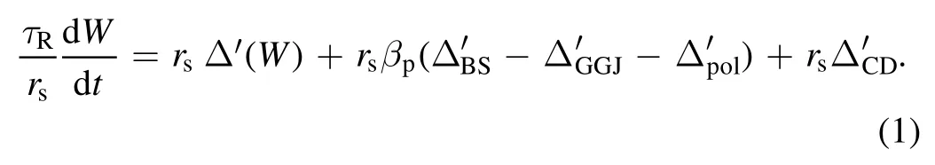
The first observation of TM mitigation by static RMP dates back to the 1970s[26–28].In 1992,Hender et al conducted a series of RMP experiments on COMPASS-C tokamak with the main concentration on the m/n=2/1 harmonics [49].The COMPASS-C is a medium-sized tokamak with the major radius R=0.557 m, minor radius a=0.2 m and toroidal field Bt=1.75 T.It is found that, in low density discharges shots, upon the static RMP turning on, the natural rotating TM with mode number m/n=2/1 decays into noise level quickly.As illustrated in figure 1, the mode amplitudes and the frequencies of TM for different flat-top current values are shown.Interestingly, this mode stabilization always happens accompanied by the downward shift of mode frequency.Two major effects of the static RMP on the natural rotating magnetic islands should be considered.First, the rotation frequency of the island is reduced by the RMP, which can directly affect the velocity shear, leading to the mode stabilizing.Second, the non-uniformity of the island rotation can cause that the magnetic island spends slightly more time staying in the regime where the static RMP is stabilizing,than where it is destabilizing.The mode stabilizing by the static RMP could be explained by the following MHD model [49].The RMP induced frequency differenceΔfcontributes to an additional term in the Rutherford equation as
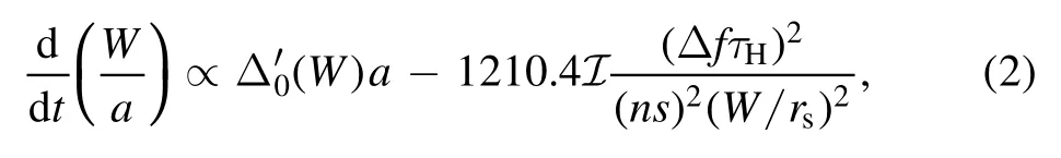
whereWis the island width, a is the minor radius,is the local hydromagnetic time-scale,rsis the radial location of the resonant surface,s=(rq′/q)rsis the magnetic shear at resonant surface and

According to equation(2),it can be easily obtained that there is a critical frequency shiftΔfcbeyond which TM is stabilized
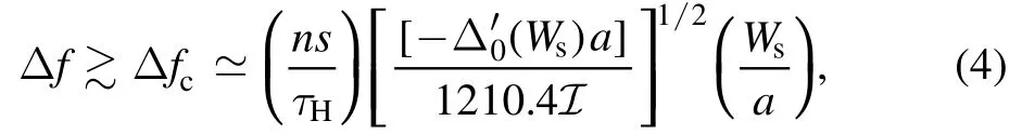
whereWsis the saturated island width.ConsideringΔf being unlikely to beyond the natural mode frequency fs,the TM can be stabilized on condition that the saturated island width bellows a threshold as

To conclude, if the saturated island width is smaller than the threshold, the TM is firstly stabilized and eventually locked by the applied static RMP as the RMP amplitude increasing.As for a large magnetic island above the threshold, the externally applied RMP can no longer be stabilizing.This mechanism is verified by many numerical and experimental results later on.
As for the static RMPs with high harmonics, they were found to change the local current density by nonlinear mode coupling and then to drive stabilizing or destabilizing effects on NTMs, even at small amplitudes below the penetration threshold[50].In the visco-resistive regime,the modification to the local current density gradient by RMPs is approximately

In the inertia dominated regime, the change of local current density gradient can be estimated by

kpand‖k are respectively the wave vectors in the poloidal and parallel direction.ω is the angular frequency of plasma rotation, τRis the resistive diffusion time, andS is the Lundquist number.In addition to the change of the local current density, the total equilibrium magnetic field becomes a weakly three-dimensional one, in the presence of static high harmonics RMPs.For instance, after applying a small 4/2 RMP,the linear growth of the 2/1 plasma vorticity is given by
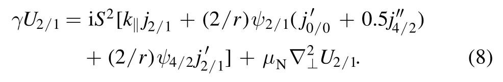
γ is the linear growth rate andμNis the plasma viscosity.Then the effect of the 4/2 RMP on the 2/1 mode stability can be estimated by the ratio of0.5j4′/2/j0′/0.One can easily find that

whereωe⊥N=(ωE0+ω*e0)τRis the normalized bi-normal fluid rotation frequency.δ is the width of the linear tearing layer.Numerical results show a good consistency with the theory introduced above.As shown in figure 2,the 2/1 NTM can be suppressed by the 4/2 RMPs with moderate amplitudes, if the bi-normal fluid rotation frequency is in the ion diamagnetic drift direction or sufficiently large.
2.2.Rotating RMP
Up until the early 2000s, considerable experiments concerning the dynamic rotating RMP are conducted on the TEXTOR tokamak [51, 52].The TEXTOR is upgraded and equipped with the dynamic ergodic divertor (DED) consisting of two tangential neutral beam injectors and a set of helical perturbation coils, which allows the production of the static or rotating RMP up to 10 kHz.In experiments [52], the equilibrium toroidal plasma rotation Ωφ,0is maintained by the carefully tuning NBI system.The static or rotating RMP is applied depending on the DC (direct current) or AC (alternating current)in DED coils.Experimental results show that,there is a threshold of current in DED coils IDEDfor the excitation of m/n=2/1 TM, illustrated in figure 3.Moreover,the value of this threshold depends strongly on the Ωφ,0at the resonant surface.There is a minimum of the threshold whenΩφ,0=2π(fDED+fe* ),where fDEDcorresponds to the frequency of the helical filed and fe* is the electron diamagnetic drift frequency.This result can be easily understood as follows.Since the magnetic field is frozen in the electron fluid,the rotation frequency of the TM in the lab frame can be expressed by the sum of the toroidal rotation and the electron diamagnetic drift frequency as

Therefore,whenfMHD=fDED,there is a minimum excitation threshold.Another interesting result is discovered [52].Keeping thefDED= -1kHz, evolution of Ωφwith the increasing IDEDis shown in figure 4 for different Ωφ,0.It is observed that, no matter what the direction and magnitude Ωφ,0is, the initial change of Ωφis always in the co-direction.Up until a sufficiently large IDEDis reached, the TM is locked to the DED field.This phenomenon can be understood by the following model.Assume the perturbed magnetic fulxψ1~exp [i (- ωt +mθ+nφ)],whereω is the frequency of RMP,m and n are the poloidal and toroidal mode number,respectively.In the generalized Ohm’s law, one can find the perturbed current density in the lowest order at the resonant surface is [53]

TheωEis the frequency due to electric drift flow,ω*eis the frequency due to the diamagnetic drift flow andη is the resistivity.The perturbed current density and the radial magnetic field will contribute to a poloidal electromagnetic torque with m/n=0/0

If the externally applied helical field is a static one,then we have ω = 0.One can find

In the MHD frame,ω*eis zero.Thus, this torque is always opposite to the direction of the plasma rotation, dragging down the plasma.On the other hand, if the diamagnetic drift is taken into consideration, the term(1+ ω*e/ωE)will determine the direction of the torque.For(1+ω *e/ωE)<0,i.e.the plasma rotates in the ion diamagnetic drift direction with a frequency smaller than the electron diamagnetic frequency,the torque is in the rotation direction.For(1+ω*e/ωE)>0,the torque is against the rotation direction.
These experimental results are then verified by numerical simulation conducted by Yu et al in 2008,using the two-fluid model[54].In figure 5,it is clearly observed that for the same RMP amplitude, the TM can be excited when the rotation frequency is close to the frequency of RMP,but screened for other rotation value,indicating that there is a minimum of the mode excitation forω = ωf.
2.3.Modulated RMP
According to the theory,it is known that the phase difference between the RMP and the magnetic island plays an important role in affecting the mode amplitude and frequency.The RMP has a stabilizing effect in the regime where the phase difference is 0.5π–1.5π, but has a driving effect when the phase difference is 0–0.5π or 1.5π–2π, as illustrated in figure 6(a)[33].The effects on the mode frequency are similar.If the phase difference is in the regime of 0–π, the RMP will decelerate the magnetic island.On the contrary,it accelerates the magnetic island while out of this regime.
Referring to this rationale, if the RMP is turned on only in the stabilizing regime, then the magnetic island can be always stabilized by this modulated RMP configuration.Based on this principle,numerical investigation is carried out by Hu et al.By applying the RMP with configuration of figure 6(b) after the saturation of NTM, the magnetic island can be almost totally suppressed.In figure 7 [33], the suppression process is plotted.In each single period, when the RMP is turned on in the stabilizing regime, the island width reduces.Even though the island width recovers a bit after the RMP is switched off,a net stabilizing effect is still maintained in one period.Period by period adding up,the magnetic island is suppressed.It should be pointed out that, this feedback control method needs a very high definition of diagnostic and control system in the experimental set-up,as it needs to know the real-time phase information of the island and the response of the modulated RMP should be very fast.Thus, the feasibility in experiments should be further verified.
2.4.Synergetic effects of RMP and ECCD
In very recent investigation, the utilization of RMP and electron cyclotron current drive (ECCD) simultaneously has been found to be an effective and promising method for NTM control.One desirable method is applying a static RMP to lock the magnetic island first, and then launching an ECCD deposited at the O-point of the island.This approach is numerically modelled in [55], and then proven to be feasible for the first time by experiments in 2015[56].Figure 8 shows the capability of stabilization of the large LM.The black curves indicate the shot with ECCD, and the red curves are for shot without ECCD.Applying a continuous ECCD after the mode is locked can effectively suppress the NTM to noise level.At the same time, the density of electron recovers and the disruption is avoided.However, there are still some side effects of this method to further prolong the energy confinement time.One main reason is that the static RMP stops the rotation of the plasma, and hinders the achievement of H-mode and better confinement.
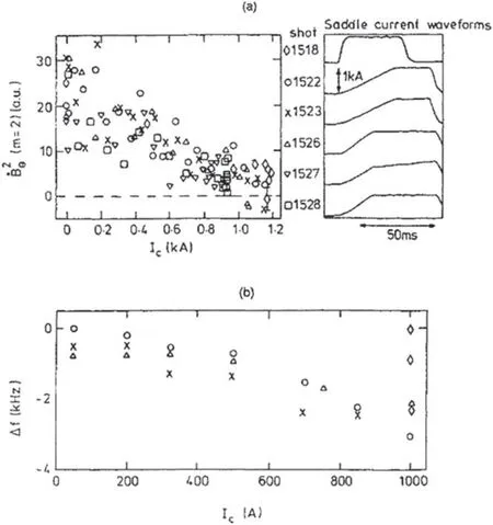
Figure 1.(a) Reduction of the m=2 coherent mode amplitude(),and(b)mode frequency shift(relative to that before the RMP is applied), with increasing (2,1) saddle current, illustrating typical‘low density’ RMP mode stabilization.Reproduced from [49].©IOP Publishing Ltd.All rights reserved.
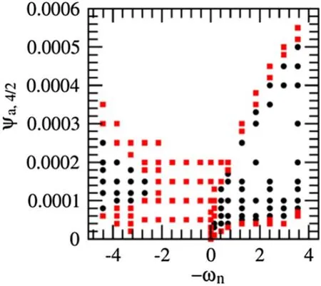
Figure 2.Stability of 2/1 NTM obtained from the four-field equations for low resistivity.The black circles(red squares)mark the cases in which the 2/1 island growth is (not) stabilized by the 4/2 RMP.Reproduced courtesy of IAEA.Figure from [50].Copyright(2021) IAEA.
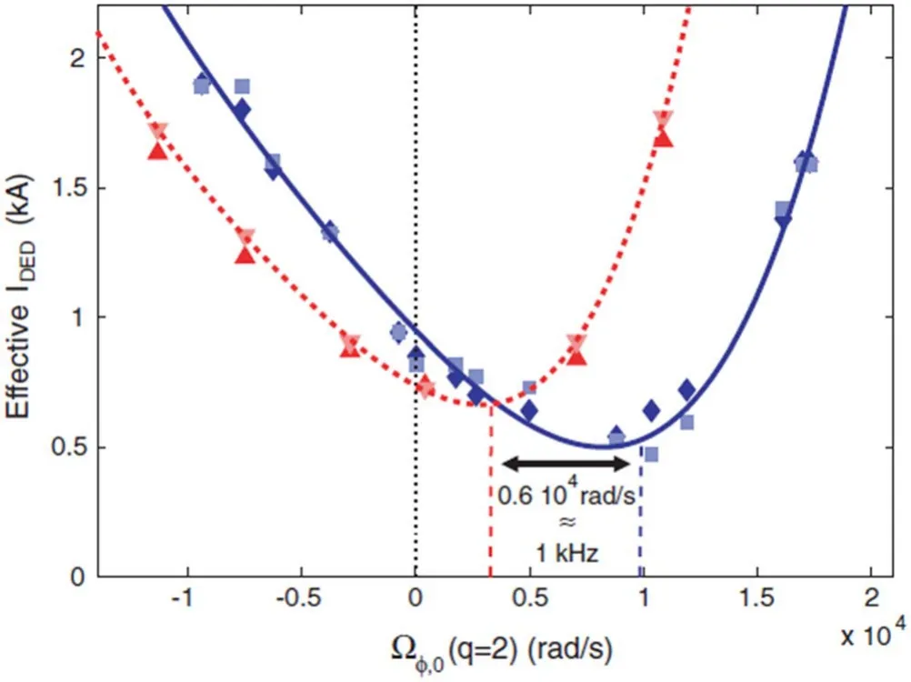
Figure 3.Threshold for mode excitation is plotted against the rotation at q=2 before the DED is applied.The density(1.5×10¹⁹ m-3)and the power input(1.5 MW)were kept constant.The data for DC DED operation(solid line,diamonds and squares)is shifted 1 kHz with respect to the data for AC+DED (dashed line and red triangles).Also, the slope of the threshold curve left and right of the minimum differs.For an initial rotation velocity right of the minimum (at the co-side) a higher DED current is needed to excite the mode than for an initial rotation velocity at an equal distance left of the minimum (at the counter-side).Reproduced courtesy of IAEA.Figure from [52].Copyright (2008) IAEA.
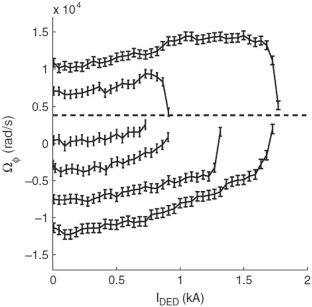
Figure 4.Ωφ, up to the moment of mode excitation, is given as a function of ID ED, for a set of discharges with a different Ωφ,0 and AC+DED operation.One observes that for low IDED the change in Ωφ is positive, i.e.in the co-direction.For plasmas with Ωφ,0 <3×10³ rad s-1 indicated by the dashed line—the change in Ωφ remains positive until Ωφ = 3×10³ rad s-1 is reached.For plasmas with Ωφ,0 >3×10³ rad s-1, the initial increase in Ωφ is followed by a decrease towards Ωφ = 3×10³ rad s-1, so the final change in Ωφ is negative or in the counter-direction.Reproduced courtesy of IAEA.Figure from [52].Copyright(2008) IAEA.
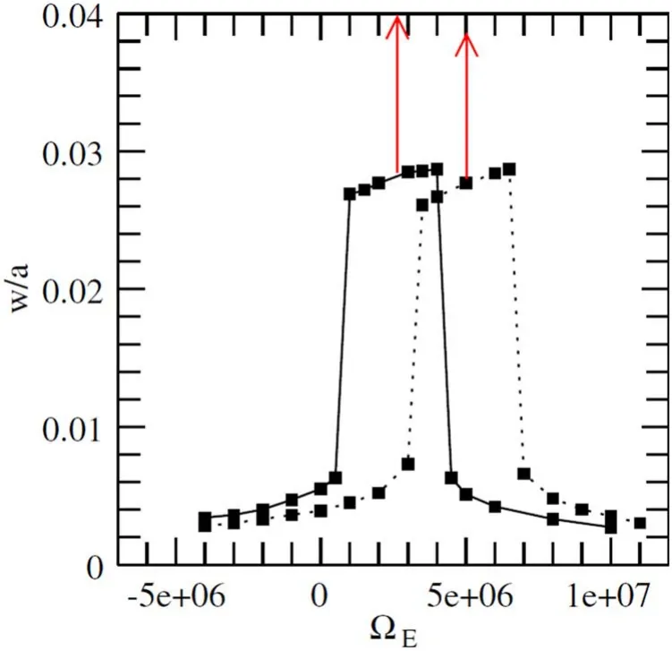
Figure 5.The island width versus ΩE for ω f= -2.2 ×10⁵ (solid)and ω f= 0(dotted), withψa =10- 5aB0t .The two vertical arrows show the ΩE value at which ω = ωf .Reproduced courtesy of IAEA.Figure from [54].Copyright (2008) IAEA.

Figure 6.(a) Diagram of the effects of RMP on TM.RMP is applied in phase region of (b) Case 1: π<Φ<1.5π, and (c) Case 2:π<Φ<2π.T is the island rotation period.Reproduced courtesy of IAEA.Figure from [33].Copyright (2016) IAEA.
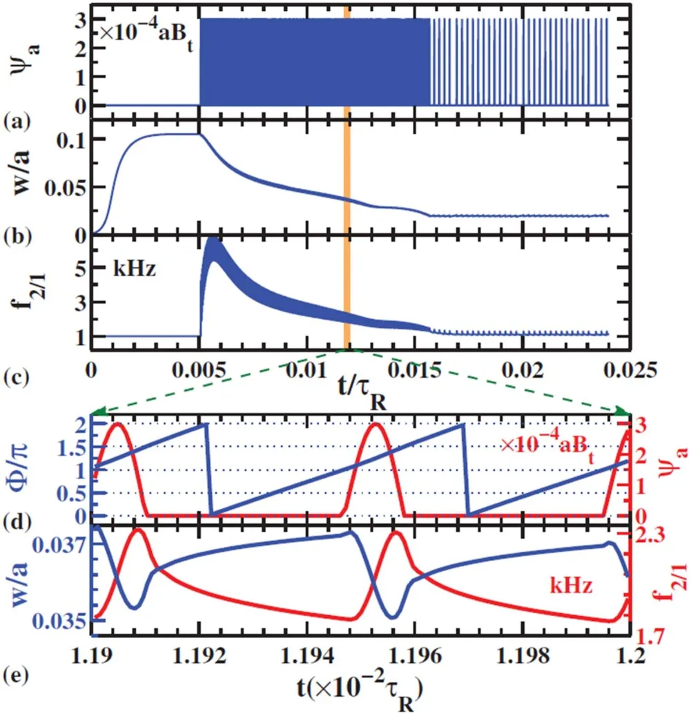
Figure 7.Case 1:time evolution of(a)RMP amplitude ψa,(b)island width w/a, and (c) mode frequency f2/1.Detailed evolution of (d)phase difference Φ(blue curve)and ψa(red curve)and(e)w/a(blue curve) and f2/1 (red curve) in the time interval of 1.19×10⁻² τR≤t≤1.2×10⁻² τR.The maximum strength of RMP is ψa=3×10⁻⁴ aBt.Reproduced courtesy of IAEA.Figure from[33].Copyright (2016) IAEA.
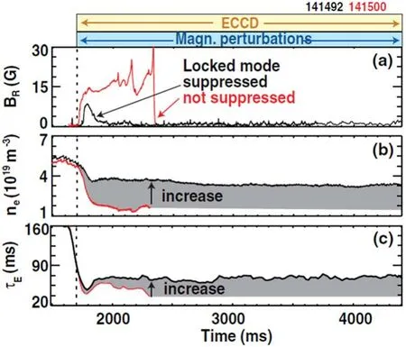
Figure 8.Increase of confinement.Suppressing the n=1 locked mode[(a),black]improves particle and energy confinement over the unsuppressed case(red),as evident for example from the electron density(b)and energy confinement time(c).Reprinted(figure)with permission from[56].Copyright(2015)by the American Physical Society.
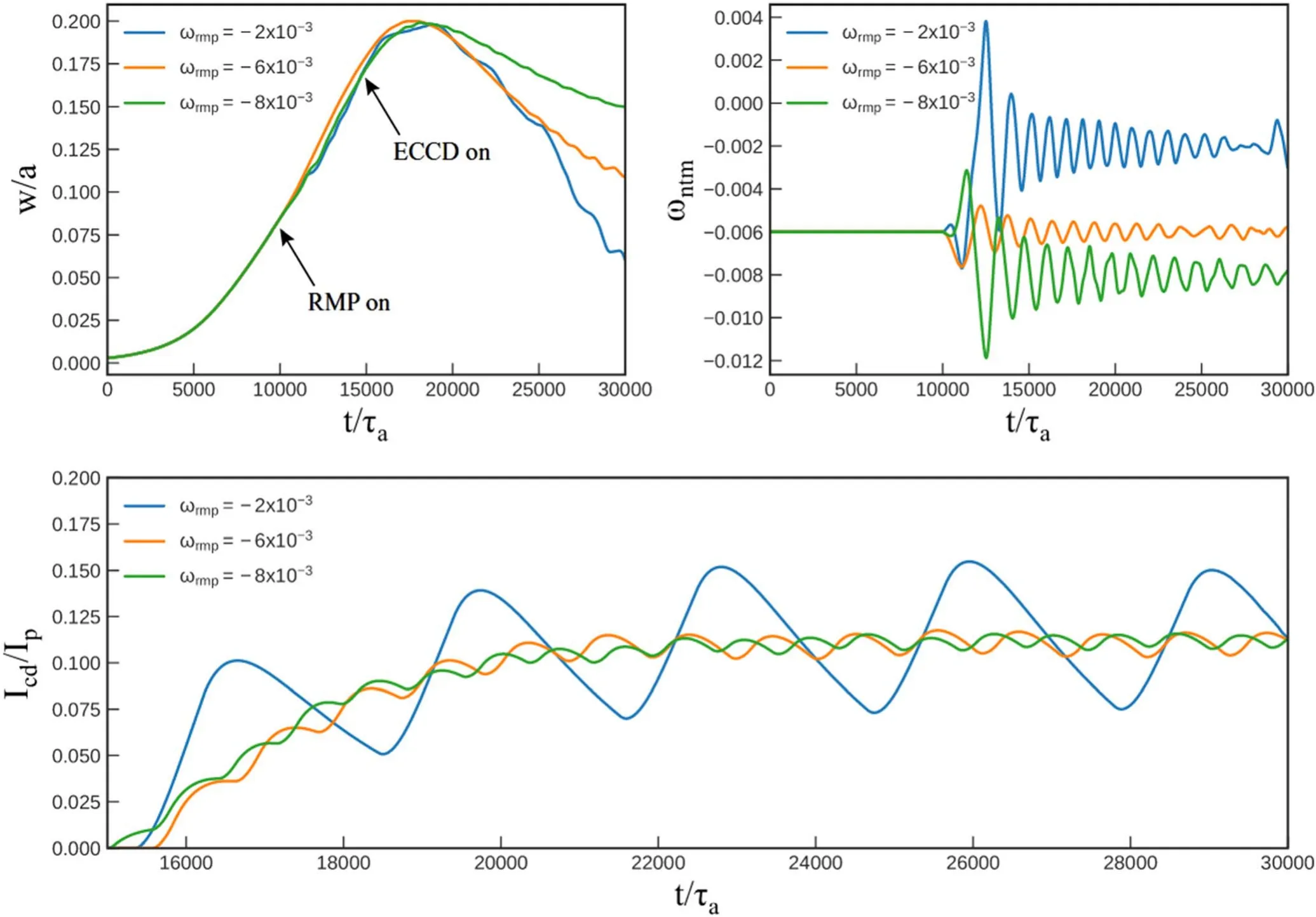
Figure 9.Evolution of island width (upper left) and mode frequency (upper right) versus time for different RMP frequencies and the corresponding driven current fraction Icd/Ip versus time(lower).The RMP is turned on at t=10 000 and ECCD is switched on at t=15 000 after the islands are totally locked by rotating RMP.Other parameters are set as ν1=2.5×10⁻³, ν2=5×10⁻⁴, r0=0.603, χ0=0.5,Δrd=0.05 and Δχ=0.20.Reproduced from [23].© IAEA.Published by IOP Publishing Ltd.CC BY 3.0.
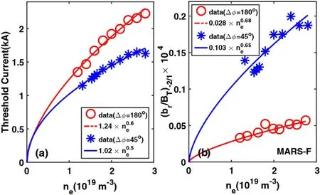
Figure 10.Density scaling with penetration thresholds represented by(a)RMP current,(b)MARS-F calculated response field.The symbols are experiment measured penetration thresholds,and the lines are fitted curves.Reproduced courtesy of IAEA.Figure from[57].Copyright(2018) IAEA.
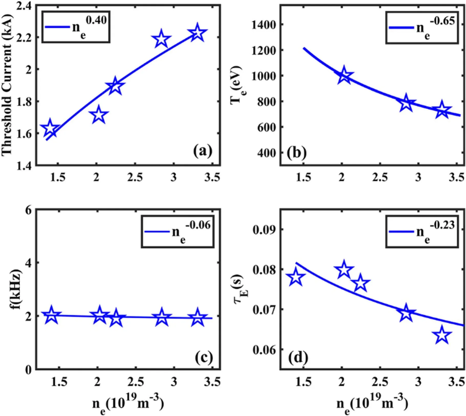
Figure 11.Observed density dependence of (a) RMP current threshold for field penetration and the solid line is the fitted curve, (b) the electron temperature at q=2 surface,(c)the mode frequency and(d)the energy confinement time.The solid lines are corresponding fitted ones.Reproduced courtesy of IAEA.Figure from [58].Copyright (2021) IAEA.
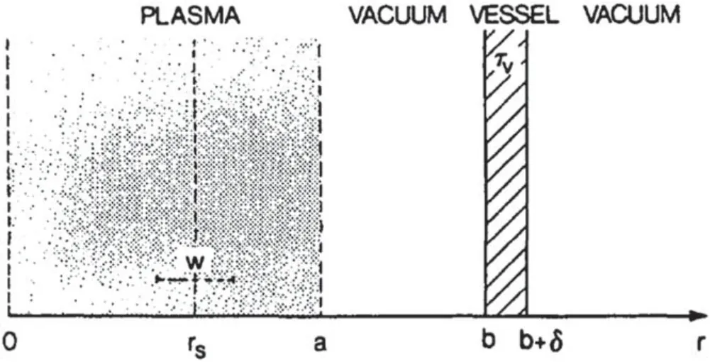
Figure 12.Geometry of the problem.Reproduced from [59].©IOP Publishing Ltd.All rights reserved.
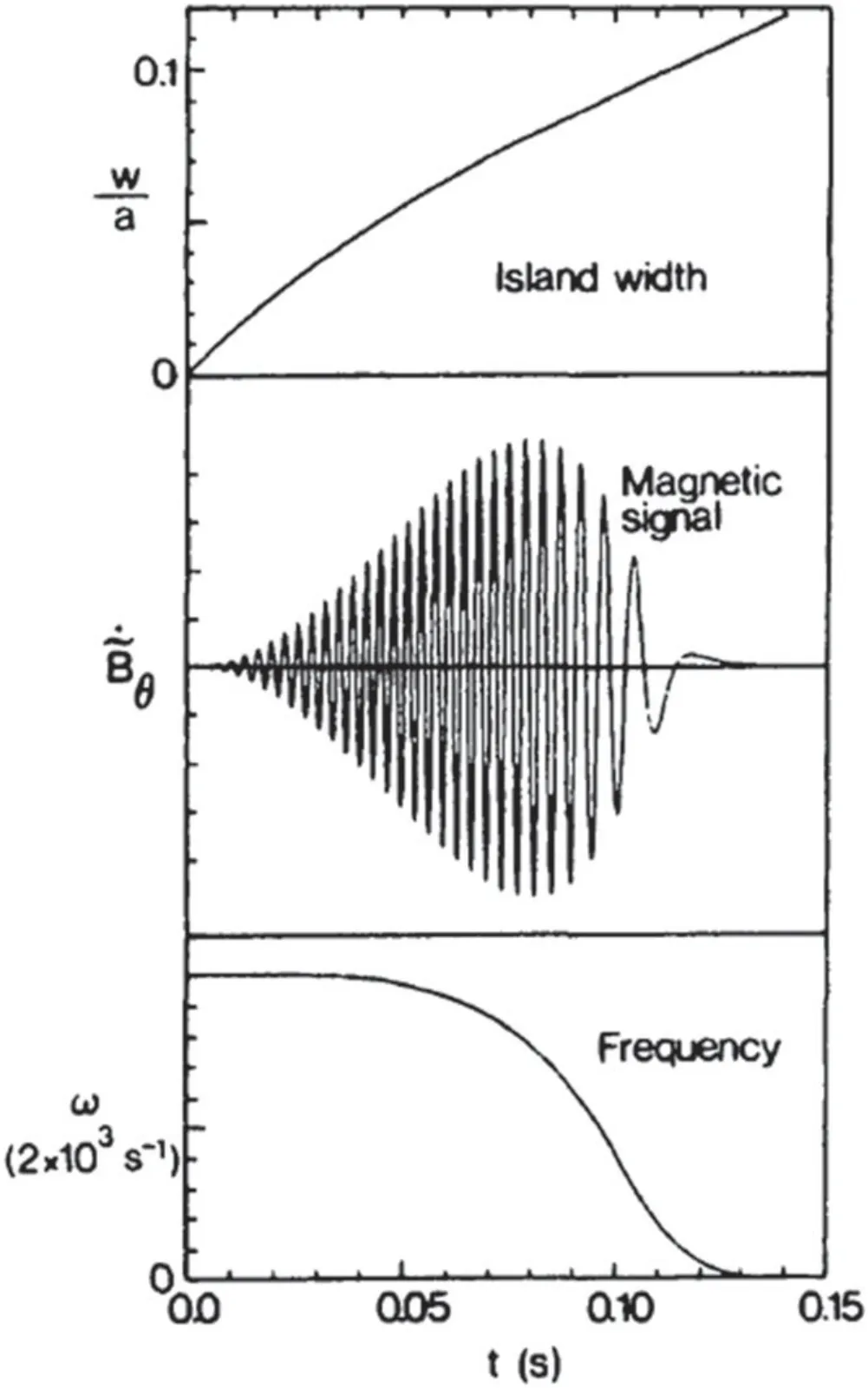
Figure 13.General behavior during mode locking.The graphs show the time development of the island width w, the magnetic signal ˙˜B and the frequency ω.Reproduced from [59].© IOP Publishing Ltd.All rights reserved.
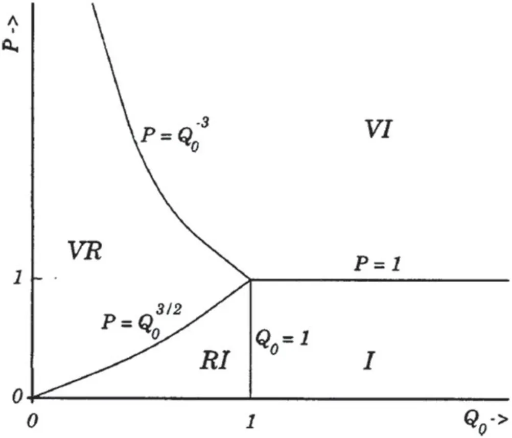
Figure 14.A schematic diagram showing the extent of the four linear response regimes in normalized viscosity, P, versus normalized plasma frequency,Q0,space.The four regimes are the visco-resistive regime (VR), the resistive inertial regime (RI), the visco-inertial regime(VI),and the inertial regime(I).Reprinted from[40],with the permission of AIP Publishing.
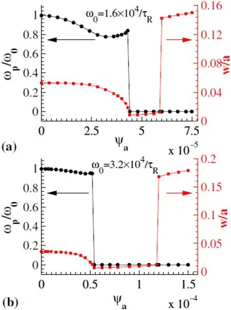
Figure 15.Normalized mode angular frequency ωp/ω0 and island width w/a at nonlinear saturation versus ψa for (a)ω0=1.6×10⁴τR and (b) ω0=3.2×10⁴τR.Reproduced courtesy of IAEA.Figure from [29].Copyright (2012) IAEA.
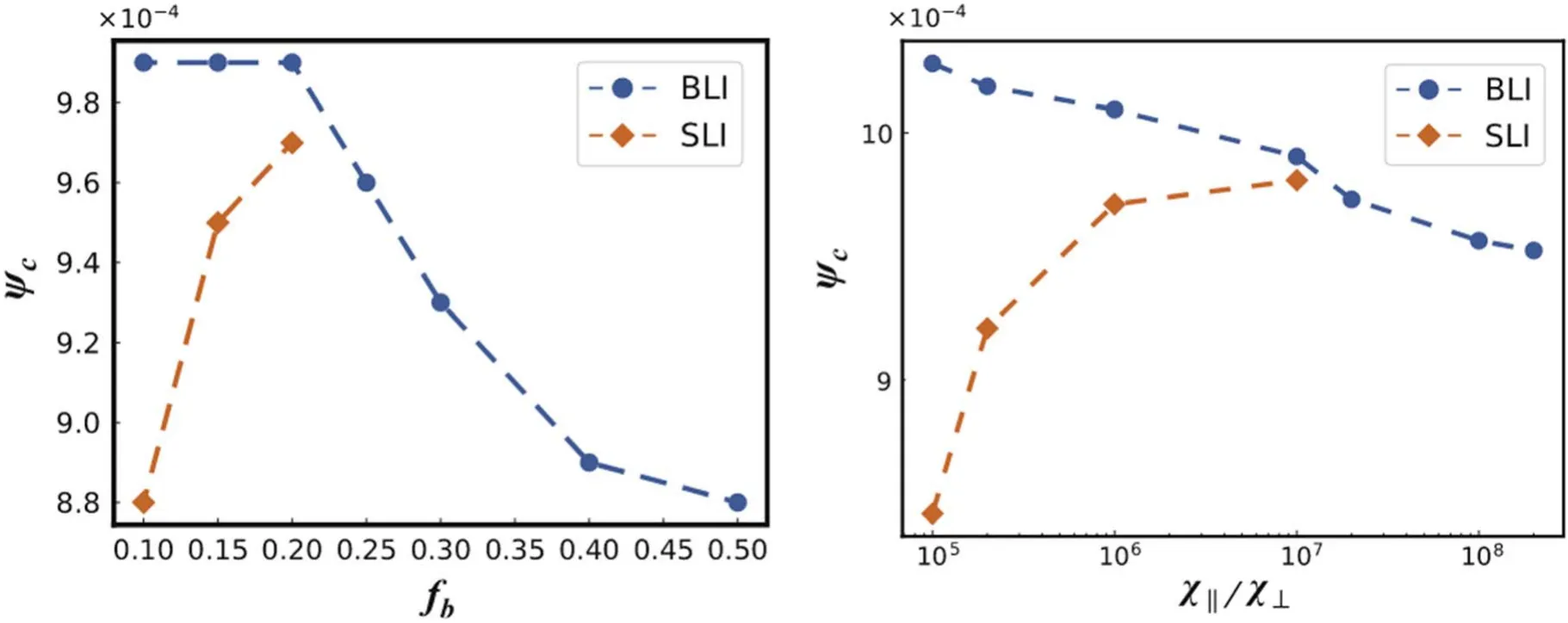
Figure 16.(left) The critical value of locked mode ψc versus the bootstrap current fraction fb.(right) The critical value of locked mode ψc versus the ratio of the parallel to perpendicular transport coefficient.Reproduced from [25].©2019 Hefei Institutes of Physical Science,Chinese Academy of Sciences and IOP Publishing Ltd.All rights reserved.

Figure 17.Red(blue)triangle indicates the case where the magnetic island evolves into the locked(oscillated)state for the external RMP amplitude and variation of the initial island rotation frequency .Solid (dashed) horizontal line represents the mode locking(unlocking) threshold.Two vertical lines with arrows are shown to clarify the hysteresis in the locking-unlocking process.Reprinted with permission from [63].Copyright (2016), AIP Publishing LLC.
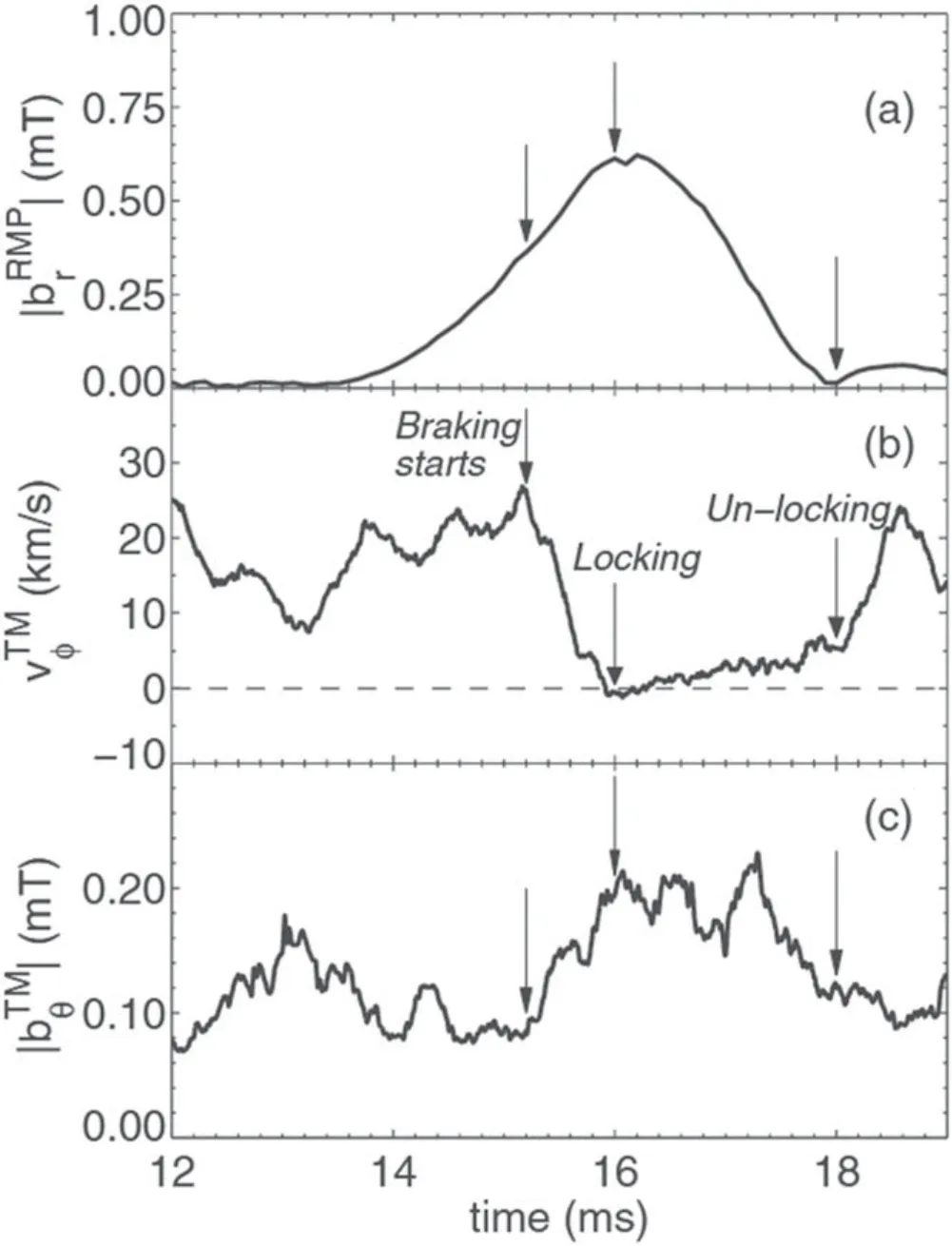
Figure 18.Time evolution for shot 25089 of (a) the applied RMP amplitude, (b) velocity of the tearing mode, (c) amplitude of the tearing mode.Reproduced with permission from [66].© 2015 EURATOM.
A possible solution to this problem is utilizing the rotating RMP.The rotating RMP could be launched first to keep a stable rotation.After the mode is locked to the rotating RMP, it is capable to use a modulated ECCD to suppress the NTM,as the real-time phase of the RMP is already known, as well as the magneticisland.ThismethodisnumericallystudiedbyTangetal for theNTM control in the reversed magnetic shear configuration[23].It is found that,for a relatively low frequency of the rotating RMP applied,the stabilizing effect is better.The mechanism can be understood through figure 9.In figure 9,the effectiveness for different frequencies of rotating RMP is compared.The blue,yellow and green traces are for the rotation frequency of RMP equal to-2×10⁻³,-6×10⁻³and-8×10⁻³,respectively.The negative sign indicates the direction of the rotation only,so only the absolute value counts.The lower panel shows the evolutionofthedrivencurrentfractionIcd/Ipversustime afterthe modulated ECCD is turned on.The on-duty ratio of the modulatedECCDissettobe50%,whichmeanstheECCDisturnedon at 50% of time in a rotation period.One can find that, for a relativelylowrotationfrequency,Icd/Iphasadequatetimetoraise or fall,in response to the magnetic island approaching and going away from the deposit location of ECCD.As a result, a better stabilizing effect is gained.Another advantage for a slow rotating RMP is that,it can lower the required modulated frequency of ECCD,since achieving a very high frequency modulated ECCD can face the technical bottleneck.
3.Mode penetration
For an intrinsic tearing stable plasma, the external RMP can penetrate through and induce magnetic islands at the resonant surface, known as the mode penetration.Mode penetration is different from mode locking by that the latter needs an already existing rotating magnetic island.Mode locking is termed to describe the process that a rotating magnetic island is stopped by the RMP and turned into a locked state.However, mode penetration is the transition from a suppressed (but locked) island state to a fully reconnected (but locked)state accompanied by the locking of the tearing frame.The frequency of the tearing frame is the frequency where the response of the tearing layer to the external RMP is maximal,called tearing frequency.For a nonlinear magnetic island,the rotation frequency of the magnetic island is identical to the tearing frequency, known as the ‘no-slip’ condition.On the other hand,in the linear state,the tearing frequency is to some extent different from the rotation frequency, allowing a suppressed island with the order smaller than the linear tearing layer.This frequency difference is called the slipping frequency.In the presence of the external helical magnetic structure, the slowing down of the plasma rotation can be described by the following equation
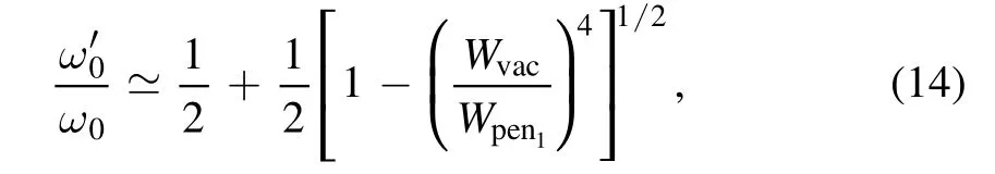
whereω0is the natural frequency,ω′0is the tearing frequency,Wvacis the vacuum island width andWpen1is a critical island width.As the external RMP amplitude increases, the slip frequency gradually decreases.Once it decreases to half of its original value, the linear system quickly transits into the nonlinear island state with the abrupt growth of the island width.
The threshold of mode penetration is pivotal in experiments,since it is used to measure the maximum endurance of the error filed.Considerable scaling on error field penetration is carried out in EAST tokamak, concerning the dependency on density, toroidal field,q95, etc.Density scaling on n=1 error field penetration of TM on EAST tokamak is investigated by Wang et al [57].During the Ohmic heating discharges,it is found that the scaling of penetration threshold on the vacuum resonant RMP isbr∝ne0.6,wherebrandneare the radial perturbed magnetic field and the line averaged electron density, respectively.For the vacuum non-resonant RMP,the scaling law isbr∝ne0.5, as shown in figure 10.On more realistic regards, it is impossible to vary the electron density while keeping other parameters unchanged.A more accurate way of obtaining the scaling law on penetration threshold is to estimate all the parameters based on the experiment data [58], e.g.the viscosity diffusion time can be estimated by the energy confinement time, asτν∝τE.By analyzing, the results agree well with the previous analytical prediction(br∝ne0.54in low density regime andbr∝ne0.40in higher density regime), providing a robust method for the scaling on error field penetration in tokamak experiments.
Later,the density scaling of n=1 error field penetration of TM in the RF-dominate heated tokamak plasmas is studied by Ye et al[58].It is found that the scaling law(br∝ne0.4)is slightly weaker than that in the Ohmic heating tokamak, as shown in figure 11.It can be understood by that the heating efficiency of the low hybrid current drive (LHCD) is closely related to the electron density.Due to the strong negative correlation between the electron density and temperature, the lower penetration threshold dependency on the electron density is obtained.These results are further verified by the MHD code MDC [58].
4.Mode locking
The earliest mode locking theory is established by Nave et al in 1990 [59], considering the interaction of the magnetic island with a resistive conducting wall.The rotating magnetic islands induce a perturbed magnetic field outside the plasma.To the conductor, this magnetic perturbation rotates with a high frequency in the order of kHz.As a result, an electric field is formed inside the conducting wall to produce a fluctuating current.The perturbed magnetic field and fluctuating current exert an electromagnetic torque j× B on the resistive wall.In the same vein, a j× B torque exists in the plasma,causing the transfer of momentum from the plasma to the resistive wall.Eventually,the magnetic island is locked to the wall.The geometry of this problem is given in figure 12[59].In the large-aspect ratio approximate, the magnetic perturbation caused the TM can be expressed as

where r is the radial location, m and n are the poloidal and toroidal mode number,ψis the magnetic flux,j is the toroidal plasma current density andθBis the poloidal magnetic field.
The boundary condition of this equation is obtained by solving the magnetic flux in vacuum and in the vessel.For the case in the vacuum, the governing equation is
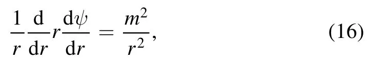
and in the vessel, the equation becomes

whereωis the rotation frequency andσis the conductivity.Through rigorous mathematical derivation, one can find
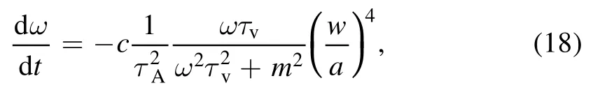
whereτvis the characteristic resistive time,τAis the Alfvén time and c is a constant.The solution to this equation is
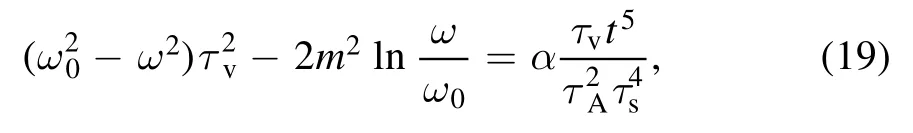
where

This is the equation showing the basic feature for mode locking.Numerical results based on this equation are given in figure 13 [59].A relatively low frequency is set to be 2000 rad s-1, with b=a andqa=4.As the magnetic island grows, the frequency starts to decrease and finally goes to zero.In 1998, Fitzpatrick established a general theory on the interaction of the magnetic island with the applied error field including linear and nonlinear response [40].The response is determined by three key parameters, the normalized plasma viscosity,P, the normalized plasma rotation,Q0and the normalized resistivity,R.The theory describes the plasma as two bifurcated states,i.e.the‘unreconnected state’,where the plasma rotates and the RMP is screened, and the ‘fully reconnected’ state, where the plasma is locked by the error field and driven more unstable.The transition from the‘unreconnected state’ to the ‘fully reconnected’ is called downward bifurcation, whereas the inverse of this process is called upward bifurcation.In the linear analysis, only the downward bifurcation exists, corresponding to the mode penetration.The bifurcation process is distinguished for four regimes,as shown in figure 14[40].The four regimes are the visco-resistive regime(VR),the resistive inertial regime(RI),the visco-inertial regime (VI), and the inertial regime (I).On the other hand, for nonlinear analysis the situation is more complicated.The nonlinear response can be divided into seven regimes, i.e.the visco-resistive regime (VR), the Rutherford regime (R), the transition regime (T), the Waelbroeck regime(W),the inertial regime(I),the high-resistivity visco-inertial regime (VI1), and the low-resistivity viscoinertial regime (VI2), see figures 3 and 4 in [52].Take the visco-resistive regime, where the present day’s conventional tokamak parameters lie in, for example, the critical RMP amplitude to trigger the downward bifurcation is given by

Experimental and numerical investigations on mode locking of TM are carried out on J-TEXT tokamak by Hu et al in recent years [29, 60].The results show a good consistence with the previous theory.
In addition to the conventional mode locking, a small locked island (SLI) regime is discovered.In figure 15, it can be seen that there is a regime where the mode frequency is locked to zero but the island width keeps in a very low magnitude, which is different from the conventional understanding on mode locking [29].It is found that two factors contribute to this SLI phenomenon.First,there exists a strong shielding current near the resonant surface cancelling the effects of external RMP.Second, the magnetic island is locked in the regime where the phase difference between the RMP and the magnetic island is 1.5π–2π, leading to a stabilizing effect on the magnetic island.
Taking the bootstrap current into account,Tang et al[25]extend this result including the neoclassical effects.It is discovered that the threshold for the SLI has the contrary tendency with the threshold for the conventional LM, as shown in figure 16.In the simulation, the SLI tends to appear in the regime where the TM is more stable, e.g.the ratio of parallel transport coefficient to perpendicular transport coefficientχ‖/χ⊥and bootstrap current fractionfbare smaller.Moreover,the island width for the SLI is almost the same.Therefore, if there is a critical island width assumed below which the SLI can be induced, the contrary tendency can be explained.According to the theory, as the amplitude of static RMP increases, the magnetic island is first slightly stabilized and then locked.For a larger bootstrap current fractionfband parallel toperpendiculartransportcoefficientχ‖/χ⊥, the saturated magnetic island is larger.To enter in the SLI regime, a larger amplitude of the static RMP is needed to suppress the island to a lower magnitude.However, if the RMP amplitude is sufficiently strong to trigger the downward bifurcation before the island is small enough for entering the SLI regime, the LM onsets and a fully reconnected magnetic island forms.In Fitzpatrick’s linear theory,the transition from the linear suppressed island to the nonlinear island state is irreversible.However, the SLI is a phenomenon that a nonlinear magnetic island returns to the linear state where the island is suppressed.Thus,perhaps the branch of this kind of solution is missed in the previous theory.
5.Mode unlocking
The mode locking of TM can lead to great degradation of plasma confinement and even major disruptions.Thus, the understanding of the unlocking process can be very significant for improving the plasma performance.From a theoretical point of view, the error field model shows a locking-unlocking mechanism [61, 62].According to the error field model developed by Fitzpatrick including the torque balance equation, island evolution equation and no-slip condition, the locking threshold can be obtained as follows[63]

whereWcis the amplitude of the external RMP,Wis the width of the magnetic island and Ω0sis the natural island rotation frequency.ΔlandΔnlare linear driving and nonlinear saturation effects, respectively.rsEscrepresents the RMP effect.
Assuming the amplitude of the RMPWcbeing a function of the island widthW, then the critical RMP amplitudeWctis the minimum value ofWcand satisfiesdWcdW=0.Substituting it into equation (22), one can get the unlocking threshold

and
Above equations give the relationship of the unlocking thresholdWctwith the corresponding island width of LMWt.
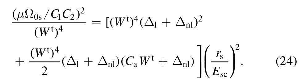
If ignoring the evolution of the magnetic island, and the island widthWis assumed to be equal to the saturated island width without applied RMPWs, the unlocking threshold can be simplified as follows [64]

It should be noted that the scaling law in simplified mode is only suitable for lower plasma parameterP, whereP= (μΩ0s(R0rs)2(m n)2) (VAWsa)2.For a broaderP,the scaling law in equations (23) and (24) is accurate, since the island evolution plays a significant role [63].
Some simulation results can show the unlocking solution more directly [63].By scanning the initial toroidal rotation frequency and the external RMP amplitude,the interaction of the RMP and the magnetic island can be classified as three regimes,namely,the locking regime,the intermediate regime and the unlocking regime.It is divided by two thresholds,locking and unlocking thresholds, as shown in figure 17.It can be seen that the unlocking threshold is lower than the locking threshold.When the RMP amplitude is larger than the locking threshold, LM would occur with arbitrary initial conditions.Lower than the unlocking threshold,the magnetic island would always enter into an oscillated state [63].However, when the RMP amplitude is between the two thresholds, the final state depends on the initial perturbed velocity, i.e.static island (δΩs∣t=0= -Ω0s) evolves into a locked state,the rotating island(δΩs∣t=0=0)would develop into an oscillated state.More interestingly, when the RMP amplitude increases from below the unlocking threshold, the natural rotating island(δΩs∣t=0=0)always keeps oscillation state until the amplitude is greater than the locking threshold.When the amplitude of the RMP decreases from above the locking threshold,the static island(δΩs∣t=0= -Ω0s)remains locked state unless lower than the unlocking threshold.
The above mentioned two kinds of behaviors in the intermediate regime can give a good explanation for the observed hysteresis phenomenon in experiments[38,64–66].For example, in figure 18, a typical shot 25089 in EXTRAP T2R [66], magnetic island starts braking att≈ 15.2 ms with RMP amplitudebrRMP≈0.4mT and LM happens att≈16.0 ms (brRMP≈0.6mT).Thereafter, the RMP amplitude ramps down to a very lower amplitudebrRMP≈0.05mT,untilt≈ 18.0 ms, the mode unlocking just occurs.In the process, when the RMP amplitude is ramped up, the electromagnetic and the viscous torque increase until locking mode occurs, where the plasma velocity reduction peaks at the resonant surface and then leads a drop of viscous torque in the core plasma,which is responsible for the hysteresis in the locking and unlocking process.
6.Summary and discussion
In summary, this paper reviews the effects of RMP on TM and NTM from the theory, experimental discovery and numerical results with a focus on four major aspects, i.e.mode mitigation, mode penetration, mode locking and mode unlocking.The main points can be summarized as follows.
For the first time mode mitigation found in experiments is by the static RMP.The externally applied static RMP is found to drive stabilizing effects on the TMs with the downward shift of mode frequency.The velocity shear and non-uniform rotation are the two main causes of the stabilizing effects.By applying a simple analytical model, it is found that the effect of a relatively small static RMP is always stabilizing, before it exceeds the threshold for mode locking.The static RMPs with high harmonics are also found to drive stabilizing effects on NTM by affecting the local current density gradient.
During the early 2000s, considerable research efforts have been dedicated to the rotating RMP.It is found that there is a minimum RMP threshold for the excitation of TM,when the frequency difference between the RMP and the plasma is zero, which means for a high frequency rotating RMP, it can be utilized to prevent the mode excitation and keep the sustainable rotation.Considering two-fluid effects, this plasma frequency should additionally include the electron diamagnetic frequency.
In recent years,some emerging RMP related methods are explored to stabilize the NTM, e.g.modulated RMP and synergetic effects of RMP and ECCD.According to the theory,The RMP has a stabilizing effect in the regime where the phase difference is 0.5π–1.5π, but has a driving effect when the phase difference is 0–0.5π or 1.5π–2π.The modulated RMP is came up based on this rationale.If the RMP is only applied in the stabilizing regime, the destabilizing effects of RMP would be eliminated and the mode locking could be prevented.However, this method needs a very high definition and fast feedback control system to locate the real-time phase of the magnetic island.Therefore, further experiments need to be carried out to verify the feasibility of this method.
Experiments of another approach, synergetic effects of RMP and ECCD, are conducted on DIIID tokamak very recently.RMP can work as an auxiliary method to lock the island.Once the island is locked to the static RMP,the ECCD can deposit at the O-point of the island continuously.The experiments have been a great success, but the energy confinement time is still hard to be further prolonged.The main reason is that the utilization of a static RMP hinders the natural rotation of the plasma, while the plasma rotation is crucial for achieving a steady-state H mode confinement.Modification of this method could be made, by replacing the static RMP by a rotating RMP.When the plasma is locked to the rotating RMP, the modulated ECCD can be launched to eliminate the magnetic island, as the phase of the RMP and the island have been already known.In this way,the NTM is controlled and the H-mode recovers.
Mode penetration is distinguished from mode locking by the absence of any rotating island before the formation of the nonlinear locked island.Mode penetration is actually a linear response of a suppressed island to the external RMP,accompanied with the transition from the linearly stable island to a nonlinear locked island and the locking of the tearing frame.However, mode locking is exactly a nonlinear response of the nonlinear rotating magnetic island to the RMP, accompanied with the locking of the already existing magnetic island.
The mode locking theory is initially established by considering the interaction between the magnetic island and a resistive conducting wall.Later on,Fitzpatrick summed up all the previous theories turning into a more general one.In the presence of a static RMP, the plasma in the vicinity of the resonant surface has two bifurcated states, i.e.the ‘unreconnected’state, where the plasma rotates and RMP is screened,and the ‘fully reconnected’ state, where the plasma is locked by the RMP and large magnetic islands are formed.The transition from the ‘unreconnected’ state to the ‘fully reconnected’state is called downward bifurcation.On the contrary,the transition from the ‘fully reconnected’ state to the‘unreconnected’ state is called upward bifurcation.In the linear response, the downward bifurcation refers to the mode penetration.For the non-inear response, the downward bifurcation corresponds to the mode locking, while the upward bifurcation corresponds to the mode unlocking.The critical amplitude of RMP to trigger these bifurcations is given analytically,by dividing the response into different regimes.The later numerical and experimental results show a good consistency with the theory established by Fitzpatrick, except that a small locked island(SLI)regime is discovered.SLI is a phenomenon that a nonlinear magnetic island returns to the linear state where the island is suppressed.Therefore, perhaps the branch of this kind of solution is missed in the previous theory.It should be pointed out that,almost all the previous theories and simulation results are based on the cylindrical geometry.The toroidal effects and the shaping effects could,to what extent,modify the results, remaining to be further addressed.
Acknowledgments
This work is supported by National Natural Science Foundation of China (No.11925501) and the Fundamental Research Funds for the Central Universities (Nos.DUT21GJ204 and DUT21LK28).
ORCID iDs
 Plasma Science and Technology2022年3期
- Plasma Science and Technology的其它文章
- A classical relativistic hydrodynamical model for strong EM wave-spin plasma interaction
- Analysis of inverse synthetic aperture radar imaging in the presence of time-varying plasma sheath
- Analysis of the influence of sheath positions,flight parameters and incident wave parameters on the wave propagation in plasma sheath
- Transmission characteristics of terahertz Bessel vortex beams through a multi-layered anisotropic magnetized plasma slab
- Measurement and analysis of species distribution in laser-induced ablation plasma of an aluminum–magnesium alloy
- Free-boundary plasma equilibria with toroidal plasma flows