
Effect of shock wave formation on propellant ignition in capillary discharge
2022-07-13 00:37JiangboZHANG张江波HongxuGAO高红旭FeiXIAO肖飞WeiLIU刘威TaixinLIANG梁泰鑫ZhongliangMA马中亮andJianWU吴坚
Plasma Science and Technology 2022年6期
关键词:江波
Jiangbo ZHANG (张江波),Hongxu GAO (高红旭),Fei XIAO (肖飞),Wei LIU (刘威),Taixin LIANG (梁泰鑫),Zhongliang MA (马中亮),∗and Jian WU (吴坚)
1 School of Environmental and Safety Engineering,North University of China,Taiyuan 030051,People’s Republic of China
2 Xi’an Modern Chemistry Research Institute,Xi’an 710065,People’s Republic of China
3 School of Electrical Engineering,Xi’an Jiaotong University,Xi’an 710049,People’s Republic of China
Abstract In order to study the effect of shock wave formation on propellant ignition in capillary discharge,the shock wave formation process was analyzed using experimental and theoretical methods;the plasma jet temperature was measured,and closed bomb and 30 mm gun experiments were carried out.The results show that the first shock wave has a smaller value and larger range of influence,while the second shock wave has a larger value and smaller range of influence.A plasma jet can generate a shock wave at the nozzle according to the calculated plasma pressure and velocity,which is well confirmed by experiments and calculations.The plasma jet temperature is high during the formation of a shock wave and then decreases sharply.Plasma ignition can increase the burning rate of a propellant by about 30% by increasing the burning surface area of the propellant.Compared to conventional ignition,the average maximum chamber pressure and average muzzle velocity of plasma ignition are increased by 9.1 MPa and 29.3 m·s-1(~3%),respectively,in a 30 mm gun.Plasma ignition has strong ignition ability and short ignition delay time due to the generation of a shock wave.By increasing the burning rate of the propellant,the muzzle velocity can be greatly improved when the maximum chamber pressure increases a little.The characteristics of the shock wave can be applied in the application of the capillary discharge plasma.For example,it can be applied in fusion,launching and combustion.
Keywords: shock wave,plasma,propellant,ignition,capillary discharge
1.Introduction
Shock waves are of interest in diverse disciplines in physics and technology,such as in astrophysics,high-energy density physics,inertial confinement fusion,aerospace technology,capillary discharge plasma and microshock channels [1-9].Capillary discharge plasma has been widely applied in fusion,propulsion,launching and combustion [10-12].
The shock waves of laser-irradiated plasma have been extensively investigated.For example,the shock waves of individual laser-irradiated nanoplasmas were studied in experiments and simulations[13].Collisionless plasma shock waves were observed in [14,15].The generation and characteristics of high-density,homogeneous plasma by capillary discharge have been studied [16-18].However,the generation and evolution of shock waves in capillary discharge plasma have not been studied.
In terms of the effect of capillary discharge plasma on a propellant,Winfrey et al[19-21]proposed a novel concept in which the ablation mechanism is forced inside of the open capillary with a propellant liner.The generation of the electrothermal plasma results from radiant heat and Joule heating transport to the liner.The discharge initiates erosive burning of the propellant,and the gasification of mixed plasma-propellant produces high-enthalpy energetic flow.Alimi et al[22,23] presented a physical and mathematical model to describe the effect of plasma jet on the burning rate of a solid propellant.The plasma induces the generation of an internal burning front that increases the burning rate of the propellant,due to the presence of reactive energetic particles in the matrix.Hang et al [24] studied the pitting effects during the pre-ignition plasma-propellant interaction process.The results show that the growth of pits increases the effective ablation area of the propellant,and thus the burning rate of the propellant is higher.Kappen et al [25] investigated the plasma radiation to the propellant and proposed that the observed structural damage of translucent JA2 (triple-base gun propellant) samples is due to radiation only.Xiao et al [26]proposed that plasma ignition presents a significantly shorter ignition delay and lower ignition energy.There is a stronger ablation and impact interaction of plasma flow with the surface of the propellant.Wang et al [27] suggested that the temperature of the plasma jet is a key factor for the enhanced burning rate of a propellant.Plasma ignition promotes the decomposition of energetic materials that are not easy to decompose by increasing the average surface temperature of the propellant,in order to improve the burning rate.Although many studies have been carried out on the interaction between plasma and propellant,the effect of a shock wave in a plasma jet on a propellant has not been considered.
In this work,a test system is established,the forming process of the shock wave is analyzed using experimental and theoretical methods; the plasma jet temperature is measured,and sealed projectile and 30 mm gun experiments are carried out.
This paper is arranged as follows.Section 2 presents the experimental setup and loading conditions.Section 3 describes the results of the experiments and simulations.Finally,section 4 presents our conclusions.
Table 1.The propellant component.
2.Experimental setup
2.1.Experimental setup in air
Figure 1 shows the schematic diagram of the experimental system.Four pressure sensors are adopted in the testing system,one of which is located in the center of the retainer plate,facing the direction of the plasma jet,at a distance of 40 mm from the nozzle.Other pressure sensors (P2,P3,P4)are installed at a position 20 mm away from the center (P1),with an interval of 20 mm from each other,and are marked as P1,P2,P3 and P4,respectively.The propellant grains(compositions are listed in table 1)are placed next to pressure sensors P1 and P4,respectively.The type specification of the pressure sensor is Kistler 6121.
Figure 1.Schematic diagram of the multipoint pressure testing system.
Figure 2.Plasma ignition test system for 30 mm gun.
The plasma generator is made of polyethylene,with an inner diameter of 3.2 mm and a length of 66 mm.A copper wire,200 μm in diameter and ~100 mm in length,connects the anode and cathode.The pulse power source has a total capacitance(C)of 750 μF and an inductance(L)of 40 μH in the equivalent circuit,R is the load plasma arc resistance and D is the diode.A high-speed camera is used to record the surface morphology of the plasma jet,using a 20 μs exposure and 50 000 fps frequency.
The temperature of the plasma jet is investigated using a spatially-resolved blazed grating spectrometer (Andor,SR-750)with a zoom lens.The entrance slit of the spectrometer is located 40 mm downstream of the nozzle and is set to 15 μm for a sufficiently high spectral resolution (0.04 nm).The signals are transmitted to the data acquisition instrument(DEWE-2600,2 MHz) and stored.
The surface conditions of the propellant after the experiments are studied using a scanning electron microscope(SEM,Keyence VE9800S).
2.2.Closed bomb experimental setup
The closed bomb volume is 100 ml.The nitrocellulose cartridge used for conventional ignition is 1.1 g and the charging voltage for plasma ignition is 8 kV.In both tests,the propellant charge is 12 g and the loading density is 0.12 g·cm-3.
2.3.30 mm gun experimental setup
Figure 2 shows the 30 mm gun experimental system.The chamber volume of the 30 mm gun is 335 ml,the run-length of projectile motion is 1660 mm and the mass of the projectile is 200 g.Conventional ignition adopts an electric primer and the charging voltage of the plasma ignition is 8 kV.Under the same loading conditions,a group of three repeated experiments are carried out to ensure the accuracy of the experiment.
Figure 3.Measured voltage and current in the experiment.
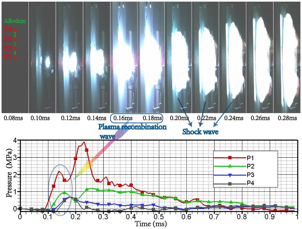
Figure 4.Characteristics of the plasma jet in the experiment.Top:high-speed camera image at different times.Bottom: measured curves of multipoint pressure,and are marked as P1,P2,P3 and P4,respectively.
3.Results and discussion
3.1.Shock wave formation
3.1.1.Shock wave experiment.The testing is carried out under a charging voltage of 8 kV,and the measured currents and voltages are presented in figure 3.The discharge duration is 0.9 ms,the peak voltage is 4.8 kV and the peak current is 18 kA.Within about 0.1 ms,the metal wire explodes electrically to form a plasma discharge channel.Then,the plasma ablates the capillary wall to form mixed steam,and the plasma discharge process is transformed into a discharge process controlled by the wall ablation.The conductivity of the mixed steam plays an important role in the plasma discharge process.
The characteristics of the plasma jet are presented at the top of figure 4.The evolution of a shock wave can be explained by the recorded plasma jet surface morphology and measured plasma jet pressure.When the time increases from 0.1 to 0.28 ms,the volume of the plasma jet increases,as can be seen from the plasma jet image taken by a high-speed camera in figure 4.However,at 0.16 and 0.18 ms,the shock front of the shock wave is significantly greater than that at 0.2 ms.This shows that there is a first peak with high intensity in the evolution of the shock wave,which we call the first shock wave.Furthermore,the image of the shock wave was also observed in [1].
The measured curves of multipoint pressure are shown at the bottom of figure 4.The first pressure peaks of P1 and P2 curves appear at 0.14 and 0.16 ms,which are 2.2 and 0.9 MPa,respectively.The only pressure peaks of P3 and P4 curves appear at 0.18 ms,which is 0.7 MPa.In addition,the occurrence time of these peak pressures is consistent with that of the first shock wave.After 0.18 ms,the pressure of P3 and P4 curves decreases and the pressure of P1 and P2 curves increases.When the time is about 0.23 ms,the second shock wave is generated,and the pressures of P1 and P2 curves reach the maximum values,which are 3.9 and 1.2 MPa,respectively.However,the pressures of P3 and P4 curves are smaller,and they are 0.4 and 0.1 MPa,respectively.That is,at positions P3 and P4,the pressure of the second shock wave is less than that of the first.Therefore,the first shock wave has a smaller value and a larger range of influence,while the second shock wave has a larger value and a smaller range of influence.
A possible reason is that plasma contains a large number of positive ions and electrons.The plasma volume expands rapidly and the temperature decreases sharply,resulting in the first shock wave.At this time,the rapid recombination of positive ions and electrons in the plasma leads to a reduction in particle numbers and interparticle forces.These factors reduce the pressure of the shock wave,which seems to be a reasonable explanation for the experimental phenomenon.
Consequently,enough attention should be paid to the first shock wave in the application of the capillary discharge plasma.For example,in electrothermal-chemical guns,the first shock wave can be used to enhance ignition under suitable propellant charging conditions.
3.1.2.Calculation of the shock wave.To study the generating process of the shock wave in the capillary,the model has been discussed in detail in our previous work [28].In accordance with the experimental conditions in this work,a half-peak current (9 kA) is used in the simulation.
Figure 5 shows the pressure of the shock waves in the capillary.Obviously,the pressure of the plasma gradually decreases from the bottom to the nozzle in the capillary.However,the pressure of the plasma is unstable at the nozzle and its value increases from 2.2 to 4 MPa.The partially enlarged map shows the wave front,which presents layer by layer,is continuously compressed and reaches the maximum at the nozzle.Then,the shock waves are generated.In addition,the plasma velocity is lower at the bottom of the capillary,as shown in figure 6.Therefore,the shock waves are concentrated at the nozzle instead of at the bottom.
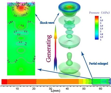
Figure 5.Pressure of the shock waves in the capillary(top left:a 2D contour map; top right: a 3D contour map).
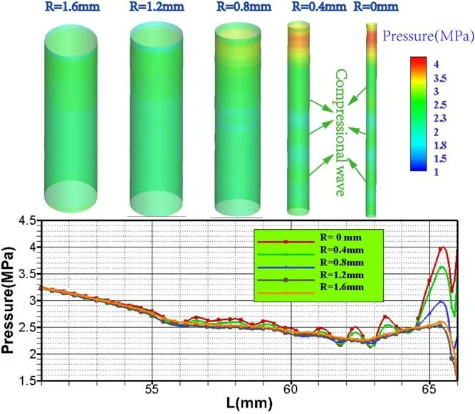
Figure 6.Pressure of the shock waves with different radial distances near the nozzle (top: slice maps).
Figure 6 shows the pressure of the shock waves with different radial distances near the nozzle,and axial length from 50-66 mm.Obviously,the pressure gradually decreases from the center to the outside with different radial positions (R=0 mm,R=0.4 mm,R=0.8 mm,R=1.2 mm,R=1.6 mm) at the nozzle,although its fluctuation is larger.The slice maps show the generated expansion and compression waves,which is very obvious near the center region(when R≤0.8 mm).Furthermore,the compression waves are further developing,and then the spherical shock waves are generated near the nozzle,as shown in figure 5.The distribution range of the plasma density is large before the axial direction of 54 mm,and narrowed at the nozzle,which corresponds to the shock waves,according to [28].
In addition,the calculated pressure curves are similar to the measured multipoint pressure curves,which shows that the theoretical calculation results are in good agreement with the experimental results.
Figure 7 shows the velocity of plasma in the capillary.Obviously,the plasma velocity is higher near the nozzle,lower in other areas,and increases sharply at the nozzle.In the 3D contour map,the plasma velocity distribution is layer by layer,high in the center and low in the outer region.In the 2D contour map,the flood presents the pressure of plasma(as shown in figure 5) and the contour line presents the plasma velocity.The plasma velocity is stagnant in the center of the shock waves,and it varies from 5000-3500 m·s-1.Furthermore,this leads to an increase in plasma pressure in the local region,resulting in the formation of shock waves.
Figure 8 shows the velocity of plasma with the different radial distances near the nozzle and the axial length from 50-66 mm.The plasma velocity increases gradually along the axial direction,ranging from 50-64 mm,then decreases rapidly until it reaches the lowest point,with an axial length of 65.5 mm,and then increases until it reaches the nozzle.The slice maps show that the plasma velocity is higher when R=0.4 mm and R=0.8 mm.
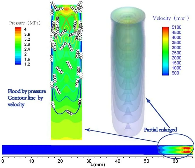
Figure 7.Velocity of plasma in the capillary (top left: 2D contour map; top right: 3D contour map).
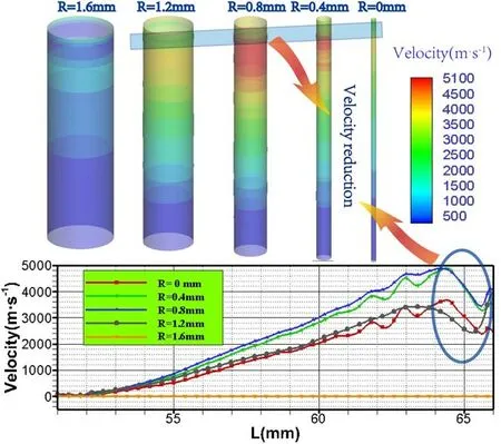
Figure 8.Velocity of plasma with the different radial distances near the nozzle (top: slice maps).
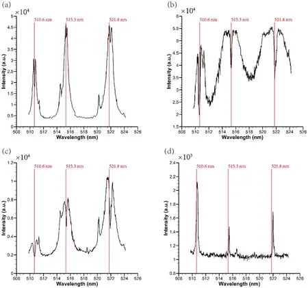
Figure 9.Spectral lines on the plasma jet axis at a position 40 mm downstream of the nozzle at different times:(a)0.14 ms,(b)0.18 ms,(c)0.22 ms,(d) 0.26 ms.
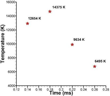
Figure 10.Estimated plasma jet temperature based on measured spectral lines.
In capillary discharge,a plasma jet can generate a shock wave at the nozzle according to the calculation results.When the shock wave is generated,the pressure of the plasma jet increases,which is well confirmed by experiments and calculations.
3.2.Plasma jet temperature
According to the principle of linear spectral radiation,the electron temperature of plasma can be obtained by combining the equations of two or more spectral lines of the same element with different high-energy excited states[29].The measured spectrum lines Cu I 510.55 nm,Cu I 515.32 nm and Cu I 521.8 nm are used to estimate the electron temperature of the plasma jet.When the plasma is in partial local thermodynamic equilibrium(LTE),the Boltzmann plot method can be used to calculate the electron temperature of the plasma [30],from:
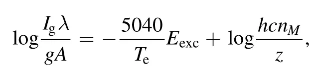
whereIgis the emission intensity of the spectral line,λis the wavelength of the spectral line,his the Planck constant,g is the statistical weight for the upper energy level of the atom,Eexcis the excitation energy of the atomic high-energy state,A is the spontaneous emission coefficient of the atom,c is the speed of light in vacuum,nMis the atomic density and z is the temperature-dependent partition function.When a particle is given,the second term on the right side of the equation is a constant.The values ofλ,g and A can be obtained from the NIST website database.Therefore,the value ofTecan be calculated.
The capillary discharge plasma ejected from the nozzle has a certain volume,which makes the distribution of electron temperature and particle density uneven in each part of the plasma.With the progress of the discharge process,the peripheral particles are gradually heated and the thickness of the peripheral low-temperature layer becomes thinner,which basically satisfies the LTE assumption.Now,the plasma temperature can be calculated by the Boltzmann plot method.The spectrum lines Cu I 510.55 nm,Cu I 515.32 nm and Cu I 521.8 nm at different times are measured,as shown in figure 9.The spectral evolution process of a plasma jet is that the linear radiation intensity increases gradually and then weakens rapidly,and the maximum value appears at 0.18 ms,as shown in figure 9(b).The plasma jet temperature is estimated according to the measured spectral lines,as shown in figure 10.The plasma jet temperature is 12654 K at 0.14 ms,14375 K at 0.18 ms,9634 K at 0.22 ms and 6495 K at 0.26 ms,respectively,which is consistent with the spectral evolution.
It can be seen from figures 4 and 10 that the plasma jet temperature is high during the formation of the shock wave and then decreases sharply.In other words,when the shock wave is generated,the plasma jet temperature is higher.
3.3.Propellant surface ablation in air
The SEM images of propellant surface ablation placed at different positions under the action of the plasma jet are shown in figure 11.In figure 11(a),the propellant is about 7 cm from the nozzle,there are more pits on the surface of the propellant,with exposed RDX particles,and the surface is generally relatively flat.More RDX particles are exposed on the propellant surface and cracks are formed,and the propellant is about 4 cm from the nozzle,as shown in figure 11(b).The shock wave has a high pressure at the P1 position (the maximum value ~3.9 MPa,as shown in figure 4 and has a strong effect on the propellant,which leads to serious surface ablation and crack formation of the propellant.At the P4 position,the shock wave has a low pressure(the maximum value ~0.6 MPa)and has a weak effect on the propellant.
The shock wave formed by the plasma jet can intensify the ablation of the propellant,resulting in the formation of surface cracks of the propellant,which will increase the combustion surface area of the propellant and enhance ignition ability.
3.4.Plasma ignition in the closed bomb
The pressure curves measured by different ignition modes in the closed bomb are shown in figure 12.In plasma ignition,the burning duration of the propellant is about 5 ms,and the maximum pressure is about 150 MPa.In conventional ignition,the burning duration of the propellant is about 7 ms,and the maximum pressure is about 165 MPa.The formed pits and cracks increase the initial surface area of the propellant,and the propellant can be ignited almost at the same time due to the high temperature of the plasma (as shown in figure 10).Therefore,the combustion time of the propellant in plasma ignition is short.In traditional ignition,nitrocellulose combustion can generate large pressure,so that the combustion pressure of nitrocellulose and the propellant is superimposed,resulting in a higher total pressure.
Figure 13 shows the burning rate curves corresponding to different ignition modes.In plasma ignition,the burning rate curve of the propellant is relatively high,and the corresponding burning rate is about 120 mm·s-1at 100 MPa.In traditional ignition,the burning rate curve of the propellant is low,and the corresponding burning rate is about 90 mm·s-1at 100 MPa.It is shown that plasma ignition can increase the burning rate of the propellant by about 30%by increasing the burning surface area of the propellant.

Figure 11.SEM images of propellant surface ablation by plasma jet.(a) Placed next to P4,(b) placed next to P1.
Figure 12.The p-t curves measured in the closed bomb.
Figure 13.The u-p curves of different ignition modes.
Figure 14.The p-t curves measured in the 30 mm gun.
Figure 15.The p-t curves of initial ignition in the 30 mm gun.
3.5.Plasma ignition in the 30 mm gun
The experimental results of a 30 mm gun with different ignition modes are shown in table 2.In conventional ignition,the fluctuation in the maximum chamber pressure is 2 MPa,and the average maximum chamber pressure is 129.5 MPa.The fluctuation in muzzle velocity is 2 m·s-1and the average muzzle velocity is 890.6 m·s-1,which indicates that the test results have good repeatability.In plasma ignition,the fluctuation in the maximum chamber pressure is 3 MPa,the average maximum chamber pressure is 138.6 MPa,the fluctuation in muzzle velocity is 0.9 m·s-1and the average muzzle velocity is 919.9 m·s-1.The results indicate that the repeatability of the experimental results is good.Compared to conventional ignition,the average maximum chamber pressure and average muzzle velocity of plasma ignition are increased by 9.1 MPa and 29.3 m·s-1(~3%),respectively.It is shown that plasma ignition can greatly increase muzzle velocity under the condition of an appropriate increase in the chamber pressure.Since plasma ignition can directly ablate and heat the propellant and its combustion gas,the pressure in the chamber increases.
The pressure curves measured by different ignition modes in the 30 mm gun are shown in figure 14.The delay time in plasma ignition is about 2 ms.Before pressure of 30 MPa,there is a rising section with a large slope on the curve,which is the enhanced combustion stage of the propellant under plasma ignition.The delay time of conventional ignition is about 7 ms,and the pressure rise is relatively gentle.Under the two ignition modes,the pressure curves of the propellant in the chamber are smooth during the whole combustion process,and the time difference when reaching the maximum pressure is 5 ms,which is consistent with the time difference at the beginning of ignition.Since the motion of a projectile makes the combustion process of the propellant in the chamber complicated,plasma ignition has little influence on the late combustion of the propellant.
The p-t curves of the initial ignition corresponding to figure 14 are shown in figure 15.The p-t curve of plasma ignition fluctuates greatly,which is caused by the shock wave generated by the plasma,and the pressure in the chamber reaches 10 MPa in 1.5 ms,which quickly ignites the propellant.Conventional ignition generates a pressure peak during ignition,followed by a slow decrease in pressure that gradually ignites the propellant.
Plasma ignition has a strong ignition ability and short ignition delay time due to the generation of a shock wave.By increasing the burning rate of the propellant,the muzzle velocity can be greatly improved when the maximum chamber pressure increases a little,which is of great significance for a high chamber pressure tank gun.
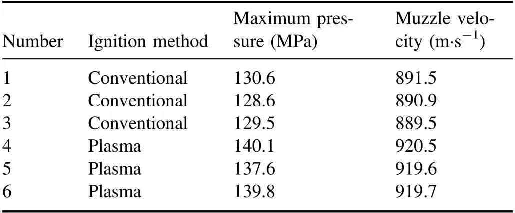
Table 2.Experimental results of the 30 mm gun.
4.Conclusion
In this work,in order to study the effect of shock wave formation on propellant ignition in capillary discharge,the formation process of a shock wave was analyzed by experimental and theoretical methods;the plasma jet temperature was measured,and closed bomb and 30 mm gun experiments were carried out.
A plasma jet can generate a shock wave at the nozzle according to the calculated plasma pressure and velocity,which is well confirmed by experiments and calculations.The first shock wave has a smaller value and larger range of influence,while the second shock wave has a larger value and smaller range of influence.The propellant near the nozzle is greatly affected by the shock wave.
The spectral evolution process of a plasma jet is that the linear radiation intensity increases gradually and then weakens rapidly,and the maximum value appears at 0.18 ms.The maximum plasma jet temperature is 14375 K at 0.18 ms,which is consistent with the spectral evolution.The plasma jet temperature is high during the formation of a shock wave and then decreases sharply.Higher plasma jet temperature is conducive to the decomposition and combustion of the propellant.
Plasma ignition can increase the burning rate of the propellant by about 30% by increasing the burning surface area of the propellant.Compared to conventional ignition,the average maximum chamber pressure and average muzzle velocity of plasma ignition are increased by 9.1 MPa and 29.3 m·s-1(~3%),respectively,in a 30 mm gun.Since the motion of a projectile makes the combustion process of the propellant in the chamber complicated,plasma ignition has little influence on the late combustion of the propellant.
Plasma ignition has a strong ignition ability and short ignition delay time due to the generation of a shock wave.The characteristics of a shock wave can be applied in the application of the capillary discharge plasma.For example,in electrothermal-chemical guns,the shock wave can be used to enhance ignition under suitable propellant charging conditions.
猜你喜欢
青春期健康(2022年21期)2022-11-30
民族高等教育研究(2022年1期)2022-04-19
东坡赤壁诗词(2022年2期)2022-04-15
科学导报(2022年18期)2022-04-10
安徽文学(2020年8期)2020-08-11
东坡赤壁诗词(2020年2期)2020-06-04
莫愁(2016年34期)2017-01-12
莫愁·智慧女性(2016年12期)2016-12-21
蓝盾(2014年2期)2014-03-06
海外英语(2013年8期)2013-11-22
 Plasma Science and Technology2022年6期
- Plasma Science and Technology的其它文章
- Recent progress on the J-TEXT three-wave polarimeter-interferometer
- Design of the stripping unit and the electromagnetic analysis unit for the E//B NPA on HL-2A/2M tokamak
- Space-resolved vacuum-ultraviolet spectroscopy for measuring impurity emission from divertor region of EAST tokamak
- Development of a combined interferometer using millimeter wave solid state source and a far infrared laser on ENN’s XuanLong-50(EXL-50)
- Bench test of interferometer measurement for the Keda Reconnection eXperiment device (KRX)
- Neutron yield measurement system of HL-2A tokamak