
An experimental study on the degradation of the C12A7 hollow cathode
2022-08-01 11:34ZhiweiHUA华志伟PingyangWANG王平阳ZhuangLUO骆壮XinZHANG张忻andLeichaoTIAN田雷超
Plasma Science and Technology 2022年7期
关键词:平阳
Zhiwei HUA(华志伟),Pingyang WANG(王平阳),∗,Zhuang LUO(骆壮),Xin ZHANG(张忻) and Leichao TIAN(田雷超)
1 School of Mechanical Engineering,Shanghai Jiao Tong University,Shanghai 200240,People’s Republic of China
2 College of Materials Science and Engineering,Beijing University of Technology,Key Laboratory of Functional Materials,Beijing 100124,People’s Republic of China
3 Shanghai Institute of Space Propulsion,Shanghai 201112,People’s Republic of China
4 Shanghai Space Engine Engineering and Technology Research Center,Shanghai 201112,People’s Republic of China
Abstract Emitter overheating is by far the greatest problem limiting the performance of novel C12A7 hollow cathodes.To explore the failure operating point and degradation mechanism of the C12A7 hollow cathode,microscopic analyses of a degraded electride emitter after 10 h of thermal electron emission are presented in this paper.The morphology and composition variation of overheated electride emitters by scanning electron microscopy,energy-dispersive spectroscopy and X-ray diffraction indicate the melting and decomposition of electride of the surface layer.The monitored temperature of the electride emitter during the C12A7 hollow cathode operation shows that to avoid overheating the electride emitter,the average current density allowed should be about 64 mA mm-2 for the C12A7 hollow cathode in its current configuration.Experimental results of the heaterless C12A7 hollow cathode demonstrate that xenon(Xe)ion bombardment can remove the insulating layer and restore the thermionic emission capability for less degraded emitters.Based on experimental results and microscopic characterization,the depletion and degradation mechanisms of electride emitters during the hollow cathode operation are discussed.
Keywords:C12A7 electride,degradation,micro characterization,hollow cathode
1.Introduction
The C12A7 electride(C12A7:e-)has attracted wide attention due to its low work function and chemical stability,despite the fact that the effective work function is demonstrated to be much higher than theoretical prediction[1–3].In 2011,Rand first applied the C12A7 electride to hollow cathode emitter materials[4].The C12A7 hollow cathode was ignited successfully and operated for several tens of minutes,while instability and frequent extinguishment of discharge existed[5].Through the joint efforts of Rand,McDonald and Drobnyet al,the stability and long duration of C12A7 hollow cathodes were achieved with modified cathode configurations and emitter shapes[6–9].The joint operations of the C12A7 hollow cathode and the Hall effect thruster(HET)have shown great potential applications in electrical propulsion[6,7,9].
From the existing literature,it is clear that the C12A7 electride is quite different to other emitter materials,such as LaB6and BaO-W[10].It has been reported to have some unique features,including a lower operating temperature,good chemical stability and reported iodine compatibility,as well as some specific failure modes[11,12].Rand,McDonald and Drobnyet alreported the overheating and melting of electride emitters during hollow cathode operation[6,11,13].Kottkeet alcompared the thermionic emission properties of LaB6and C12A7.Due to problems with the surface effect and the electrical contact of the electride,the maximum emission current was measured as 1.3 mA,which was much lower than that of LaB6[10].The degradation of the electride was also noted during work function tests.Randet alat Colorado State University developed an experimental apparatus for measuring the work function of a C12A7:e-sample.The results showed that the work function increased as the number of tests increased until no current was detected.They hypothesized that the development of a layer on the C12A7:e-surface after discharge might cause a decrease and the eventual cessation of electron emission[4].McDonaldet alreported degradation of a low-current C12A7 hollow cathode ignited with an external heater.The main characteristic was an increase in anode voltage from 140 to 180 V after 4–5 h,suggesting an increase in emitter temperature[8,11].Randet alalso reported instabilities and higher anode voltages of the heaterless C12A7 hollow cathode due to surface contamination[11,14].
In general,the C12A7 electride hollow cathode is still immature compared to conventional LaB6and BaO-W hollow cathodes due to reproducibility problems and reported failure cases.Due to inadequate understanding of the C12A7:ematerial,as well as the microscopic mechanisms of electride electron emission,the failure mechanisms of C12A7 hollow cathodes are rarely investigated.Researchers work on improving the hollow cathode configuration to enhance the performance of the C12A7 hollow cathode,including specific configurations,cathode materials and electrical setups.The microscopic changes in electride emitters before and after discharge,which might provide a theoretical basis to avoid degradation or failure are seldom studied[7].
In the previous experiment,the external heating C12A7 hollow cathode achieved stable discharge and joint operation with a low-power HET for hours.Degradation trends of the hollow cathode were observed,mainly in the form of increased ignition temperature[15].The degraded C12A7 hollow cathode could not be ignited after 20 ignition cycles.The electride emitter of degradation was removed and investigated using scanning electron microscopy(SEM),energy-dispersive spectroscopy(EDS)and x-ray diffraction(XRD)to study the microstructure,morphology and components of the electride emitters before and after discharge.Variations in the composition and morphology of the emitting surface are discussed to provide some explanation for emitter failure and degradation.Differential thermal analysis(DTA)and the thermogravimetric(TG)method are used to investigate the melting temperature of the electride material applied in the C12A7 hollow cathode experiments.To find the exact operating point of emitter overheating,the emitter temperature of C12A7 hollow cathodes is monitored and recorded at the stage of ignition and self-sustained discharge.To verify whether the degraded electride emitter can be restored by plasma bombardment,heaterless C12A7 hollow cathode experiments are also carried out simultaneously.
2.Experimental section
2.1.C12A7:e- emitter
[Ca24Al28O64]4+(e-)4(C12A7:e-)is an electride material that is stable in the atmosphere up to 300°C due to its unique framework built by 12 sub-nanometer-sized cages with~0.4 nm diameter inner free space,as can be seen in figure 1(a).The rigid structure of the lattice framework with Ca–O and Al–O bonds prevents the anionic electrons in the cages from being attacked by O2and/or H2O in the external environment,as shown in figure 1(b).Meanwhile,the anionic electrons are weakly trapped in these cages so that they can easily be transferred to the adsorbate at the surface by quantum tunneling[1].
The tested C12A7:e-emitters were provided by Zhanget alat Beijing University of Technology[16–18].Benefitting from their efforts in the processability of the C12A7 electride,the cylinder electride was successfully fabricated into a hollow cylinder using cutting tools,as shown in figure 2.The fabricated tubular C12A7:e-emitter has a solid black appearance before discharge.
2.2.Hollow cathodedesign
A C12A7 hollow cathode equipped with a heater was developed and tested in Shanghai Jiao Tong University,as shown in figure 3.Compared to traditional hollow cathodes,the configuration of the C12A7 hollow cathode looks short and thick for rapidly transferring heat from the emitter to the flange.In the configuration of the C12A7 hollow cathode that encountered the degradation problem,the orifice diameters of the keeper and cathode tubes,made of molybdenum,are 2 and 1 mm,respectively,and the length of the two orifices is 1 mm,while the gap between them is 2 mm.In the temperature measurement experiments,the orifices of the keeper and cathode are both enlarged to expose the emitter so that the electride temperature during hollow cathode operation can be directly measured by an infrared double-wave temperature indicator.
2.3.Experimental facility and test instruments
The C12A7 hollow cathodes were operated in a vacuum chamber that was 0.4 m in diameter and 1.2 m in length.High vacuum pumping was provided by two molecular pumps with a capacity of 2000 l s-1.The background pressure in the vacuum chamber can reach 2×10⁻⁵Pa.The Xe propellant has a purity of 99.9995%.The backpressure of the individual operation of C12A7 hollow cathodes varied from 5×10⁻³to 5×10⁻²Pa.Due to the compact size of the vacuum chamber,the background pressure in the chamber may sometimes reach 1×10⁻¹Pa in the joint operation with a Hall thruster.Excessive background pressure can have an impact on the performance of the hollow cathode and electride emitter,which will be further investigated in the future.The electrical setup of hollow cathode experiments is shown in figure 4[15].
The constituents of the electride emitters were analyzed using an X-ray diffractometer(DMAX-IIIB,Cu Kα radiation,k=1.5418 Å).The microscopic morphology of the sample internal/external surface and cross-section was characterized with the help of an FEI NANOSEM 200 model high-resolution SEM.
3.Results and discussion
3.1.External heating hollow cathode
As in a previous study,an external heater was developed to heat the emitter to its operating temperature to avoid uncontrolled discharges at the ignition stage,which could cause emitter overheating.With the external heater,the electride hollow cathode was successfully ignited and operated quite stably,as shown in figure 5.The C12A7 hollow cathode was operated for a total of 10 h,including three exposures to the atmosphere,as well as a joint operation with a HET at 200 W for 3 h.It worked at 1 A most of the time,while the maximum current reached 4 A[15].As the number of ignitions increased,there was a tendency for the ignition of the C12A7 hollow cathode to become slow and difficult,although the discharge looked quite stable once it was successfully ignited.The C12A7 hollow cathode needs to be ignited at a slightly higher heating current and higher mass flow rate.The Xe mass flow rate also increased from 5 to 10 sccm.The keeper voltage varied from 350 to 750 V.The required heating current was increased from 5.8 to 6.1 A when the emitter temperature exceeded 1200 °C.It was demonstrated that the C12A7 hollow cathode could not be ignited with the external heater after 20 ignition cycles,regardless of the heater power,mass flow rate and keeper voltage.
To verify that the degradation of the hollow cathode was caused by the electride emitter itself(instead of the heater or other components),the degraded emitter was reloaded into another hollow cathode.It has the same key component dimensions as the previous one,but the overall size is smaller and more compact.The hollow cathode could still not be ignited with the heater,even if the temperature was already high.Other emitters in this batch of electrides also underwent degradation during the experiments of external heating of C12A7 hollow cathodes.
It is noted that the resistance of C12A7 electride is higher than that of LaB6of the same size.Measurement of the resistance of a cylindrical emitter using a multimeter shows that the resistance of the C12A7 electride emitter is tens to hundreds of ohms,much higher than the 0.6 Ω of LaB6.The high surface resistance of the C12A7 electride emitter is caused by the presence of the surface electron-deficient layer[19].
The resistance of the electride emitter increased to thousands of ohms or nearly insulated after discharge of the C12A7 hollow cathode.Changes in the surface resistance of this material may be the cause of the ignition failure of the C12A7 hollow cathode.This indicates that the C12A7 electride material has undergone some kind of change during electron emission and needs to be studied using microscopic analysis.
3.2.Micro characterization of electride
3.2.1.SEM-EDS characterization.To investigate the degradation mechanism of C12A7 hollow cathodes,the degraded electride emitter before and after discharge was dissected for visual inspection and subsequent microscopic examination using an SEM to examine the microfeatures of the emitters.Straightforward images of the emitter’s internal surface and images of the interior of the emitters after crosssectioning were acquired.The electride emitter degradation after discharge is shown in figure 6.The degraded emitter had a 5 mm outer diameter,2 mm inner diameter and 10 mm length.After 10 h of discharge,the exterior surface of the emitter became porous and rough,as well as having slight shifts in color.
Figure 7(a)shows an SEM image of the end surface and internal surface of the C12A7 electride cylinder emitter before discharge.There is a clear boundary between the two surfaces.The end surface of the electride is compact,commonly crystalline,and rarely contains spaces between grains.The internal surface was quite smooth where the machining marks made by cutting tools were easily observed.
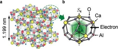
Figure 1.(a)Schematic illustration of the[Ca24Al28O64]4+(e-)4(C12A7:e-)crystal.(b)Magnification of a cage with S4 symmetry axes passing through two axial Ca ions and the cage center that can trap an electron(green-shaded region).

Figure 2.Tubular C12A7 electride emitter(after fabrication).

Figure 3.Section view of the C12A7 hollow cathode with a heater.

Figure 4.Electrical schematic of the cathode test setup.

Figure 5.Discharge of the C12A7 hollow cathode and its joint operation with a 200 W HET(Vkeeper=350 V, Ianode=1–4 A,2–5 sccm Xe).

Figure 6.Degraded C12A7:e- emitter after discharge.

Figure 7.SEM images of the end surface of the electride emitters.(a)Fabricated electride emitter before discharge.(b)Degraded electride emitter after discharge.
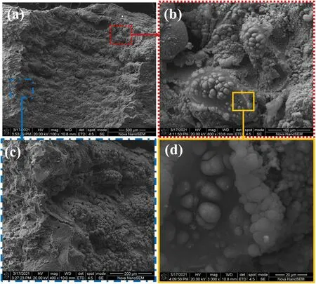
Figure 8.SEM images of different resolutions on the emission surface of the degraded electride emitter.(a)Cross-section of the degraded emitter,magnification 100.(b)Bubbles and melts in the red region,magnification 800.(c)Comparison of the inner core area and surface morphology in the blue region;magnification 400.(d)Magnified display of bubbles in the yellow region;magnification 3000.
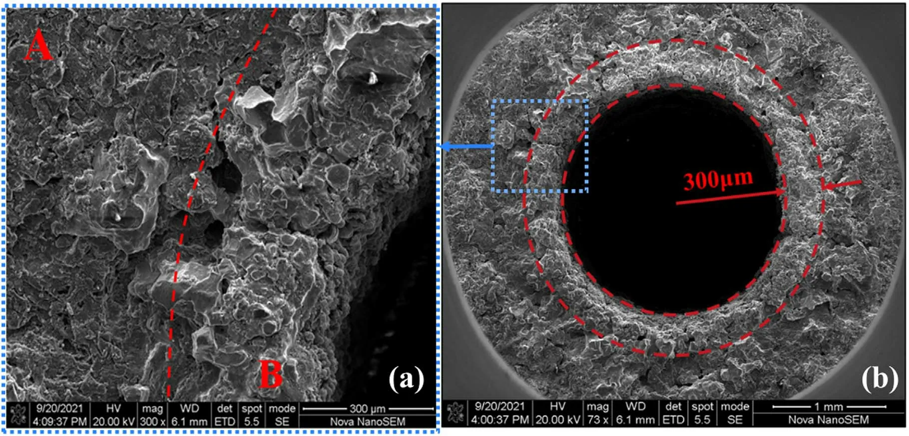
Figure 9.SEM images of the cross-section of the degraded electride emitter.(a)Region A is the layer away from the emission surface,and region B is the layer close to the emission surface.(b)Ring-shaped discolored area with a width of about 300 μm.
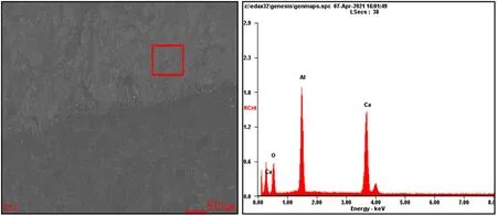
Figure 10.SEM-EDS of the electride emitter(before discharge).
Compared to figure 7(a),the end surface of the electride emitter after discharge becomes coarse and porous,where more holes and cracks are observed.Some spherical particles are dispersed on the internal surface,as shown in figure 7(b).The SEM images of the internal surface at different resolutions,which is mainly the electron-emitting surface,are shown in figure 8.
Grooves and craters appeared on the internal surface of the emitter after plasma bombardment.Dense spherical and large granular vesicles were detected in SEM images with a higher resolution.There are scattered bubbles on the melt area of varying sizes on the internal surface of the cylinder emitter.It is speculated that when the emitter was heated for thermal electron emission,the top layer of the electride would begin to foam due to the ohmic heat produced by the insulating or semiconducting layer.Even if the hollow cathode was operated at comparatively low current,parts of the electride close to the cathode orifice would partly melt because of ion bombardment.The partial fusion extent is associated with the electride temperature,which is determined by the extracted current during hollow cathode operation.With the expansion of the melting zone,these melts gathered together,resulting in softening and deformation.When the discharge is terminated,the emitter temperature decreases gradually.These melting areas will become cold and then recrystallize.
The cross-sectional image of the emitter after dissection is shown in figure 9.The area near the emitting surface is distinctly different to the other areas.It looks whitish and has a sparser tissue density.This part might be the decomposition area,and its depth is approximately 300 μm,which probably provides a valuable reference for emitter depletion in C12A7 hollow cathode models.
Based on the morphology of the etching figures after discharge,we speculate that once discharge occurs,the electride emitting surface pills at first and then melts partially as the discharge continues.As the extracted current increases,the ohmic heating from the current passing through the resistive emitter will increase rapidly.A large amount of heat is trapped on the electride due to poor thermal conductivity,and the melting areas expand and gather together,finally causing softening or deformation of the emitter.
Despite the micromorphology of the electride emitter after discharge,the elementary compositions of these emitters have also been investigated using EDS and XRD to study the impact of hollow cathode discharge on the electride.Figure 10 and table 1 provide the SEM-EDS results of the electride emitters of C12A7 hollow cathodes before and after discharge.The atomic ratios of specific elements measured using EDS are shown in table 1.
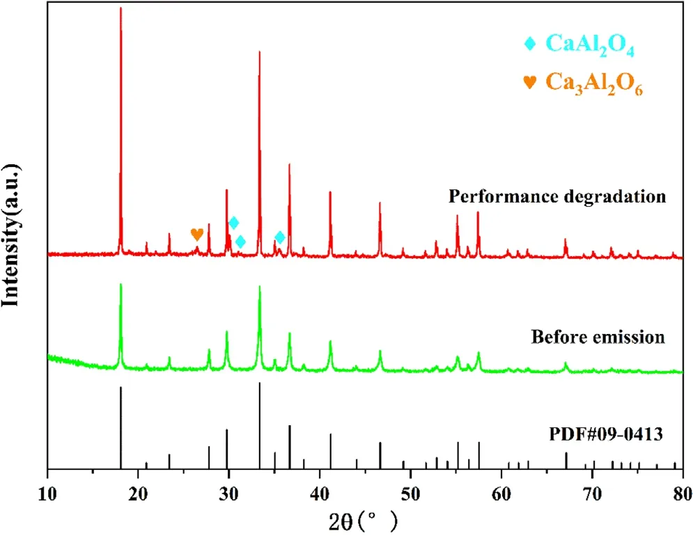
Figure 11.XRD patterns of C12A7 electride emitters before and after discharge.
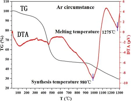
Figure 12.TG-DTA curves of the synthetic process from C12A7 precursor to the C12A7:e-.

Figure 13.Schematic of the temperature measurement of the electride emitter with an infrared double-wave temperature indicator.
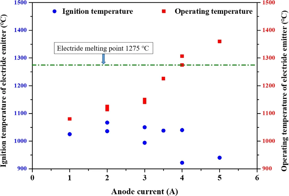
Figure 14.Electride emitter temperature of ignition and operation at different anode currents.
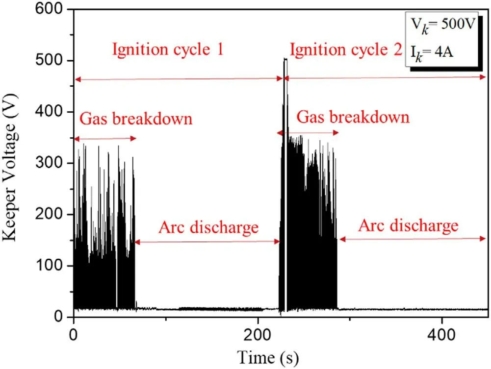
Figure 15.Variation of keeper voltage in two continuous ignition cycles.

Figure 16.Heaterless C12A7 hollow cathode(Vkeeper=500 V,Ikeeper=4 A,18 sccm Xe).(a)Gas breakdown of Xe.(b)Arc discharge.
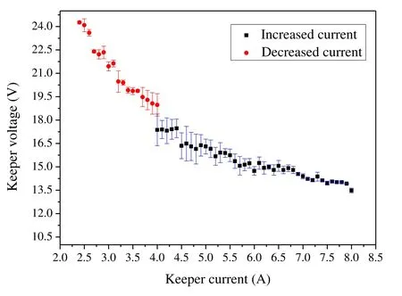
Figure 17.Keeper voltage versus keeper current at a set mass flow rate(18 sccm Xe).
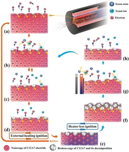
Figure 18.Depletion and degradation mechanism of C12A7 electride emitters during hollow cathode operation.(a)–(e)Thermionic emission and surface layer degradation of the electride emitter in the discharge of a C12A7 hollow cathode ignited with an external heater.(e)–(h)Elimination of the degradation layers on the electride surface and the restoration of thermionic emission capability in the discharge of a heaterless C12A7 hollow cathode.
To eliminate the interference of impurity elements(including Fe,C,etc)from the stainless steel and graphite components of the hollow cathode,the EDS results of the measured regions consisting mainly of Ca,Al and O are introduced in table 1.The element ratios of Ca to Al in regions at the end surface and the internal surface are respectively 21.17%:25.65% and 21.28%:24.33%,roughly equivalent to 6:7,indicating that the Ca/Al mole ratio nearly exactly matched the standard stoichiometric ratio in the C12A7 electride(12CaO·7Al2O3:4e-).With regard to the appearance,color and EDS results,it is believed that the machining process has little impact on the constituents of the C12A7 electride.
As shown in table 1,the Ca/Al element ratio on the internal surface of the degraded emitter is 30.15%:18.49%,roughly equivalent to 3:2,indicating that the Ca/Al mole ratio is nearly matched with Ca3Al2O6(C3A).The Ca/Al element ratio in another region of the internal surface is 24.48%:28.87%,roughly equivalent to 6:7,indicating that theCa/Al mole ratio nearly matched that of 12CaO·7Al2O3(C12A7).

Table 1.The atomic ratios of specific elements(at%)measured using EDS in different regions of the C12A7:e-emitters before and after discharge.
In addition to the emitting surface,the profile composition of the degraded emitter was also tested.The element ratio of Ca and Al at the cross-section close to the internal surface(region B in figure 9)is 19.92%:35.9%,which is roughly equivalent to 1:2,indicating that the Ca/Al mole ratio nearly exactly matches that of CaAl2O4(CA).The element ratio of the obtained electride at the cross-section away from the internal surface(region A in figure 9)is Ca:Al=23.24%:29.26%,roughly equivalent to 6:7,indicating that the Ca/Al mole ratio exactly matched C12A7.
Based on the SEM-EDS results,it can be concluded that the decomposition of electride occurred mainly around the emitting surface where melting and recrystallization existed.The decomposition temperature might be quite close to the melting temperature.The decomposition components were detected in the region hundreds of microns below the emitting surface,indicating that electride decomposition has a very strong effect on the loss rate of the emitter.To improve the cathode lifetime in the future,it is important to avoid decomposition of the emitter caused by overheating.
3.2.2.XRD characterization.To reduce the impact of the inaccurate EDS measurement for light elements,especially oxygen concentration,the crystal structure and phase composition of the electride emitters before and after emission were characterized by powder XRD,as shown in figure 11.The electride emitter after fabrication,using cutting tools,is completely consistent with the standard diffraction data card of C12A7(PDF:09-0413)in the position of the diffraction peak.
In the electride degradation,some miscellaneous phases mainly consisting of CaAl2O4(CA)and Ca3Al2O6(C3A)were detected.According to the SEM and EDS results,these miscellaneous phases mainly appeared on the internal surface of the hollow cylinder emitter,where thermionic emission occurred.This means that the C12A7 electride will be decomposed into C3A and CA in an inert gas at high temperature.The decomposition products of C3A and CA are insulated.It then attaches to the emitter’s internal surface when the hollow cathode is terminated and prevents the electrons from freely escaping from the electride surface,presenting difficulty in the next ignition of the C12A7 hollow cathode.The main phase of the emitter is still C12A7:e-and the electride hollow cathode could be ignited at a higher emitter temperature.Once the hollow cathode is ignited,the discharge of the electride hollow cathode looks just as stable as before because these decomposition products will be eliminated soon by Xe ion bombardment.
3.2.3.TG-DTA analysis.To further investigate the phase transition temperature of the electride emitter,the process from the C12A7 precursor to the C12A7 electride is analyzed using a synchronous thermal analyzer.The measurements were carried out in an argon atmosphere from 30 °C – 1300 °C,as shown in figure 12.In this temperature range,there are four main weight loss processes.The first weight loss is due to the removal of water from the precursor,which occurs at around 100 °C.The second apparent sustained weight loss of about 40%between 350 °C – 550 °C is due to the transformation from nitrate to oxide or volatilization of organic matter in the precursor.Third,there is an endothermic peak in the range of 900 °C – 1150 °C and the TG curve shows a further weight loss of about 5% at this stage,indicating a reduction reaction from C12A7 oxides to C12A7:e-[20].Fourth,there is another endothermic peak at 1275 °C,which is produced by the melting of the C12A7 electride,and the TG curve shows a further weight loss of about 5%.The decalescence and weight loss of the electride indicate that it begins to melt when heated to 1275 °C,which is slightly higher than the reported value from Kim and Hosono(1230 °C)[21].
3.3.Temperature of the C12A7 emitter during hollow cathode operation
Microscopic analysis shows that the melting temperature of the C12A7 electride is approximately 1275 °C and that the decomposition temperature is also very close to the melting temperature.Therefore,temperature monitoring of the electride emitter of the hollow cathode under specific operating conditions is important to avoid degradation and melting problems.Due to the narrow space and the plasma environment inside the hollow cathode,the temperature measurement of the emitter itself is difficult.In previous research,the temperature of the cathode orifice plate has usually been measured to estimate the temperature of the emitter of BaO-W or LaB6[22].The temperature difference between the orifice plate and the emitter could be tens of degrees,which might be unacceptable for the C12A7 emitter,considering the low thermal conductivity and overheating sensitivity of the C12A7 electride.
Therefore,a modified hollow cathode is applied to measure the temperature of the electride emitter during steady-state operation.The inner diameter of the new electride emitter was 2 mm,as before,while the diameters of the cathode orifice and the keeper were enlarged to 2.5 and 3.5 mm,respectively.Consequently,the inner emitting surface of the emitter was exposed to the line of sight.As shown in figure 13,this setup allows direct temperature measurement of the emitter with an infrared double-wave temperature indicator.
The measurement error of the infrared thermometer was evaluated before operation of the hollow cathode.A thermocouple and infrared thermometer are used to measure the temperature at the same point near the emitter.With a fixed heating power of about 80 W,the thermocouple shows a value of 925°C,and the pyrometer gives a result of 926.3°C in steady state.Compared to thermocouples,the error measurement of the infrared thermometer was found to be no greater than 2°C,and its response was faster.
During operation of the electride hollow cathode,the Xe mass flow rate was fixed at 10 sccm and the keeper power supply was set at 350 V/1 A.The temperature of the electride emitter appeared on the meter and was recorded by a camera throughout the process before the ignition and after shut down.The temperature increased rapidly until the C12A7 hollow cathode was ignited with an external heater.It should be noted that when the discharge occurred,the bright plasma plume instantly drowned out the infrared signal from the emitter.Therefore,there is no effective infrared ray signal during cathode operation.The temperatures in figure 14 are recorded at the last moment before ignition and the first moment after the plume disappears when the discharge is stopped.The temperature response to the hollow cathode operation is timely without any obvious delay.As shown in figure 14,it is believed that the ignition temperature of the electride emitter is between 1000 °C – 1100 °C,which is consistent with the conclusion based on thermocouple measurements in previous research[15].In the ignition experiments with an anode current of 4 and 5 A,the measured temperature was lower because the sparking and flicker before ignition interrupted the infrared signal early.It still took one to two seconds to be heated before the ultimate formation of arc discharge.
The operating temperature of the electride emitter was 1080 °C with an anode voltage of 1 A,and increased rapidly with the increased extracted currents of the C12A7 hollow cathode.When the anode current reached 4 A,the temperature of the electride emitter was greater than 1275°C,which is the melting temperature of electride based on TG-DTA results.Despite the temperature difference produced by cathode orifice modification,it can be concluded that the degradation of the C12A7 hollow cathode was caused by partial melting and decomposition due to emitter overheating.The allowable working temperature of the electride emitter is 1275 °C,and the maximum emission current density of the C12A7 hollow cathode with the configuration should be below 64 mA mm-2(4000 mA/(2 mm×3.14 mm×10 mm)).The experimental data in figure 14 also provide a critical reference for the modeling and simulation of C12A7 hollow cathodes,which saves more time and costs for engineering design and demonstration.
3.4.Reactivation experiment of the degraded C12A7 hollow cathode
According to microscopic analysis of the electride emitter after discharge,the electride degradation is caused by the decomposition layer on the emitter surface at high temperature.The insulating surface phases probably consist of Ca3Al2O6,CaAl2O4,C12A7:O2-and amorphous C12A7:e-,causing difficulties in thermionic emission.The degradation is believed to be a surface effect because the emitter material in the core region remains the C12A7 electride.It is natural to reactivate the degraded emitter by removing the surface insulating layer.Rand had treated the electride material surface with an external Ar+plasma source to maintain a high level of electron emission in the work function measurement experiment[9].Inspired by this,the C12A7 hollow cathode with degraded electride emitter was tested with the heaterless ignition method,using the discharge plasma generated by high-voltage electrical breakdown to clean the insulating layer.
During the test,the heater power supply was kept off and the electride hollow cathode was ignited directly from room temperature.A typical voltage variation during the heaterless ignition stage is shown in figure 15;the power supply of the keeper was set at 500 V/4 A.As the Xe gas entered the hollow cathode,gas breakdown occurred instantly and the keeper voltage oscillated violently from 500 V to tens of volts.Frequent flicker and a blue plume were seen in the keeper’s exit plane,indicating a breakdown of Xe atoms,as shown in figure 16(a).The ion bombardment eliminated the decomposition on the electride surface and also heated the emitter to its emitting temperature.After 56 s of gas breakdown,the hollow cathode was shifted into arc discharge mode.The voltage was kept stable at about 20 V and the current was kept at 4 A,as shown in figure 15.The plasma plume gradually stabilized and the color turned from blue to purple,as shown in figure 16(b).
The volt-ampere characteristics of the C12A7 hollow cathode with a set mass flow rate are shown in figure 17.Compared to the C12A7 hollow cathode ignited with an external heater,the keeper voltage of the heaterless C12A7 hollow cathode is higher than before[15].This is understandable because the overall temperature of the heaterless hollow cathode is still lower at the moment of ignition.The keeper voltage will be kept high to warm the emitter for sufficient electron emission.According to the voltage fluctuations and plume conditions,it usually takes more time,about ten minutes,to achieve a stable discharge for the heaterless C12A7 hollow cathode.In addition to tests at low current(2–4 A),the C12A7 hollow cathode also achieves stable discharge at current up to 8 A.Although operation at higher current may lead to rapid depletion of the electride emitter,it also proves that the overall performance of the emitter is not significantly affected.
A total of ten ignition cycles of the heaterless C12A7 hollow cathode were performed.Ignition could always be started in about a minute.It is believed that the reported degradation occurs on the emitter surface and has an impact on the ignition of the external heated hollow cathode,while it can be reactivated by plasma bombardment.The verified activation case of the degraded electride emitter was only in operation for a few hours and at 4 A current.Whether electride emitters in severe degradation cases can be reactivated in this manner requires further study.
3.5.Depletion and degradation mechanism of electride emitters
Based on the experimental phenomena of the C12A7 hollow cathodes and the microscopic characterization of the emitter after discharge,the microscopic behavior of the electride during the cathode operation is described to reveal the depletion and degradation mechanism of the electride emitter.
In a typical externally heated hollow cathode,the emitter is heated to a certain temperature where abundant electron emission can occur.Unlike BaO-W and LaB6materials,the surface resistance of C12A7 electride is unusually high due to the presence of a thin electron-deficient layer,as shown in figure 18(a).The insulating layer is thin with a thickness close to the cage radius of C12A7.For the first-time working electride,thermionic emission is usually available with a comparatively high ignition temperature(1000°C–1100°C).
After losing electrons in the nanocages,the C12A7 electride framework is likely to collapse at high temperature and decompose into C3A and CA.The decomposition products have lower melting points and are unable to hold or transfer electrons.This may decrease the probability of a tunneling event of electrons jumping from cages to the vacuum beneath the decomposition layer,as shown in figure 18(b).If the arc discharge of the hollow cathode is established at this point,the Xe ions will bombard the surface of the emitter under the action of the electric field and the cathode sheath potential.These insulating layers are quickly removed and the thermionic emission is restored and sustained,as shown in figure 18(c).The emitter is also depleted layer by layer during the cycle of electron removal,electride decomposition and cleavage of the decomposition layer,as can be seen in figures 18(b)and(c).
However,if the ignition parameters are improper and the arc discharge cannot be formed for a long time,the insulating layer on the electride surface will become thicker,resulting in complete ignition failure,as shown in figure 18(d).Similarly,when the discharge is stopped,the electride emitter is still hot and the thermionic emission and electride decomposition remain while the bombardment of the emitter surface by highenergy ions is no longer sustained.The decomposition layers are eventually attached to the surface of the emitter and influence the electron emission properties when the hollow cathode cools down,as shown in figure 18(e).
The thickness of the insulation layer after discharge depends on the overall temperature and duration of the emitter.The decomposition layer is roughly estimated to be located from the inner surface of the cylindrical emitter(where the temperature is highest)to the inner core layer(where the temperature is approximately 1275°C or lower).
For the next ignition,the C12A7 hollow cathode could be ignited with an external heater,probably requiring higher power to maintain sufficient electron emission.However,the hollow cathode will completely fail to start if the decomposition layer is too thick,as shown in figure 18(f).To reactivate the electride,a high-voltage pulse can be applied between the emitter and keeper in order to electrically break down the Xe propellant.The produced Xe ions continuously bombard and clean the decomposition layer,as shown in figure 18(g).The electride is also heated simultaneously to the ignition temperature for thermionic emission until the discharge shifts into arc discharge mode,as shown in figure 18(f).During the operation of the C12A7 hollow cathode,the process of emitter depletion and degradation is the same as shown in figures 18(b)and(c).
4.Conclusion
During the C12A7 hollow cathode experiments,it was found that ignition with the external heater became increasingly difficult.To investigate how and when the degradation problem of the C12A7 hollow cathodes occurs,the degraded electride emitter was characterized using SEM,EDS,XRD and TG-DTA.Based on the C12A7 hollow cathode experimental phenomena and microscopic characterization of the electride emitter,it is concluded that the difficulty in cathode ignition is caused by electride degradation on the emitter surface.
The SEM and TG-DTA results indicate that the electride material is temperature-sensitive,easy to overheat,and may directly lead to emitter softening and deformation when operating at higher current.The results of the infrared thermometer measurements showed that the operating temperature of the emitter temperature is below 1100 °C with an emission current density of 16 mA mm-2,and exceeded the melting point(1275 °C)when the average emission current density reached 64 mA mm-2.The EDS and XRD results showed that the C12A7 electride will decompose into C3A and CA at high temperature and the attached decomposition layer has an impact on the thermionic emission capability of electride at lower layers.
Experimental results of heaterless C12A7 hollow cathodes with the degraded electride emitter demonstrated that the degradation occurs on the emitter surface and can be removed by plasma bombardment.The thermionic emission capability of degraded electride can be restored and the hollow cathode can be ignited directly from room temperature in one minute.
Finally,the depletion and degradation mechanism of electride emitters during hollow cathode operation is presented based on experimental results and microscopic characterization.This qualitatively describes the change in electride layers on the emitter surface after the release of electrons and its effect on the subsequent discharge.
These experimental results and conclusions are based on a few cases and samples.More quantitative studies on the effect of different operating parameters on the degree of electride degradation need to be conducted.Whether the heaterless ignition method is always efficient for the C12A7 hollow cathode also needs to be further confirmed.
Acknowledgments
This work is supported by the Joint Fund for Equipment Pre-research and Aerospace Science and Technology(No.6141B061203).
猜你喜欢
东坡赤壁诗词(2020年2期)2020-06-04
边疆文学(2020年5期)2020-05-22
科学之友(2020年4期)2020-05-19
神州·中旬刊(2017年4期)2017-08-02
现代交际(2017年11期)2017-06-30
现代交际(2017年11期)2017-06-30
南方文学(2017年2期)2017-06-09
北方文学·中旬(2016年9期)2016-12-08
廉政瞭望(2009年10期)2009-11-30
语文教学与研究(读写天地)(2009年2期)2009-03-06
 Plasma Science and Technology2022年7期
- Plasma Science and Technology的其它文章
- Characteristics of plasma in a novel laserassisted pulsed plasma thruster
- The effect of anode axial position on the performance of a miniaturized cylindrical Hall thruster with a cusp-type magnetic field
- Investigation into the thermal effect of the LIPS-200 ion thruster plume
- Early experimental investigation of the C12A7 hollow cathode fed on iodine
- Numerical study of the effect of aft-loaded magnetic field on multiple ionizations in Hall thruster
- Simulation of a helicon plasma source in a magnetoplasma rocket engine