
Enhanced single photon emission in silicon carbide with Bull’s eye cavities
2022-10-26 09:49XingHuaLiu刘兴华FangFangRen任芳芳JiandongYe叶建东ShuxiaoWang王书晓WeiZongXu徐尉宗DongZhou周东MingbinYu余明斌RongZhang张荣YoudouZheng郑有炓andHaiLu陆海
Chinese Physics B 2022年10期
Xing-Hua Liu(刘兴华) Fang-Fang Ren(任芳芳) Jiandong Ye(叶建东) Shuxiao Wang(王书晓)Wei-Zong Xu(徐尉宗) Dong Zhou(周东) Mingbin Yu(余明斌) Rong Zhang(张荣)Youdou Zheng(郑有炓) and Hai Lu(陆海)
1School of Electronic Science and Engineering,Nanjing University,Nanjing 210023,China
2State Key Laboratory of Functional Materials for Informatics,Shanghai Institute of Microsystem and Information Technology,Chinese Academy of Sciences,Shanghai 200050,China
Keywords: single photon sources,4H-SiC,Bull’s eye cavities,color centers
1. Introduction
Quantum photonics, which is involved in the emerging quantum information technologies such as quantum communication, metrology, sensing, and quantum computation has been developed rapidly over the past few decades.[1]In the quest for realizing all these applications, robust, and efficient single photon sources(SPSs)on demand are highly desirable.Single photon emission has been demonstrated among a variety of physical systems, including trapped atoms, trapped ions, molecules, quantum dots (QDs), and color centers in wide-bandgap semiconductors.[2]Of the above different types of emitters,color centers in wide-bandgap semiconductors are considered as one of the most promising single photon emitters because it does not need to operate at cryogenic temperatures and has potential in integrated photonic circuits on chip.
For an ideal SPS, a high brightness or emission rate, directional radiation, a high single photon purity, and indistinguishability are required. However,many free-standing semiconductor SPSs do not show distinct superiority in device performance compared with their counterparts due to the isotropic angular emission pattern and intrinsic low emission rate.[3]These limit the collection efficiency of emitted photons and the operating speed of whole system. Great efforts have been made to improve semiconductor SPSs by coupling the emitters with various photonic microcavities such as micropillars,[4]micro-disk,[5]and photonic crystals[6,7]to enhance intrinsic emission into the zero-phonon line (ZPL). In particular, by employing photonic crystal cavities in QDs and wide-bandgap semiconductors for enhancing photon emission, high quality factors were indeed achieved, whilst the improvement of farfield profile was still weak. The cavity-induced Purcell effect,which shortens the radiative lifetimes of the emitters,will also improve photon indistinguishability on short time scales.[8]
Bull’s eye geometries are capable of photon extraction from emitters, in which the circular Bragg gratings (CBGs)serve as a resonant cavity that enables an enhancement of spontaneous emission rate with highly directional emission and therefore a higher photon collection efficiency. So far,the CBGs have been employed to enhance photon collection efficiency from QDs or color centers in diamond.[9,10]Silicon carbide(SiC)and diamond share most of the favorable properties of color centers in wide-bandgap semiconductors that are used for single photon emission. However, the implementation of Bull’s eye cavities in an SiC-based SPS is still vacant to be of our best knowledge.
In this work,we present a design by introducing CBG into a 4H-SiC-based SPS where the emitter is embedded in a micropillar cavity in the center,i.e.,the so-called Bull’s eye cavity. Three-dimensional finite-difference time-domain(FDTD)method was employed to calculate the emission rates and farfield distributions of a target color center. With optimized geometric parameters,a bright and vertically emitting SiC-based SPS can be realized.
2. Design and simulation
An emitter in an optical cavity will experience a mediumenhanced radiation rate relative to that in a homogenous medium given by the Purcell factor(FP)[11]
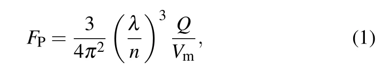
whereλis resonant wavelength in free space,nis the refractive index of cavity material,Qis the quality factor,andVmis the volume of the cavity mode. The exciton will radiate faster in a cavity than in free space if the Purcell factor is higher than one. The Purcell enhancement can be achieved by increasing the ratio of the quality factor to the mode volume,i.e.,Q/Vm.Here the quality factor (Q) is defined asQ=λ/FWHM,[12]where FWHM (full width at half-maximum) can be determined from the resonance intensity spectrum. The mode volume of a dielectric cavity is calculated using the ratio of the total electric energy to the maximum electric energy density[13]whereεis the permittivity andEis the electric field.

The schematic diagrams of the proposed SiC-based SPS and the referenced structures are shown in Fig. 1. Structure A is an SiC epitaxial on an SiC substrate wafer without any nanostructures. According to Ref. [14], we suppose an oxidation-related color center in 4H-SiC whose luminescence spectrum displays a peak around wavelength of 600 nm.Structure B with a micropillar cavity surrounding the color center can be formed by window etching on structure A.By introducing a CBG structure into structure B,we expand to structure C with a Bull’s eye cavity which potentially enables an improved Purcell factor due to a higherQ-factor and a smaller mode volume. The Bull’s eye cavity is also capability of far-field modulation for an improved emission directionality. The top-view and cross-sectional schematics of structure C are sketched in Figs.1(b)and 1(c),respectively. Here,r,Λ,g,w,anddrepresent the cylinder radius,grating period,teeth width,and the width and depth of the etched circular trenches. The number of the teeth around the central cylinder is denoted by the period numberN. Given that a pure dielectric antenna can preferably avoid the metal-related ohmic loss and emission quenching,[15]we use an all-dielectric design for the Bull’s eye cavity due to the potential of higher Purcell enhancement and the ease of fabrication process.[16]
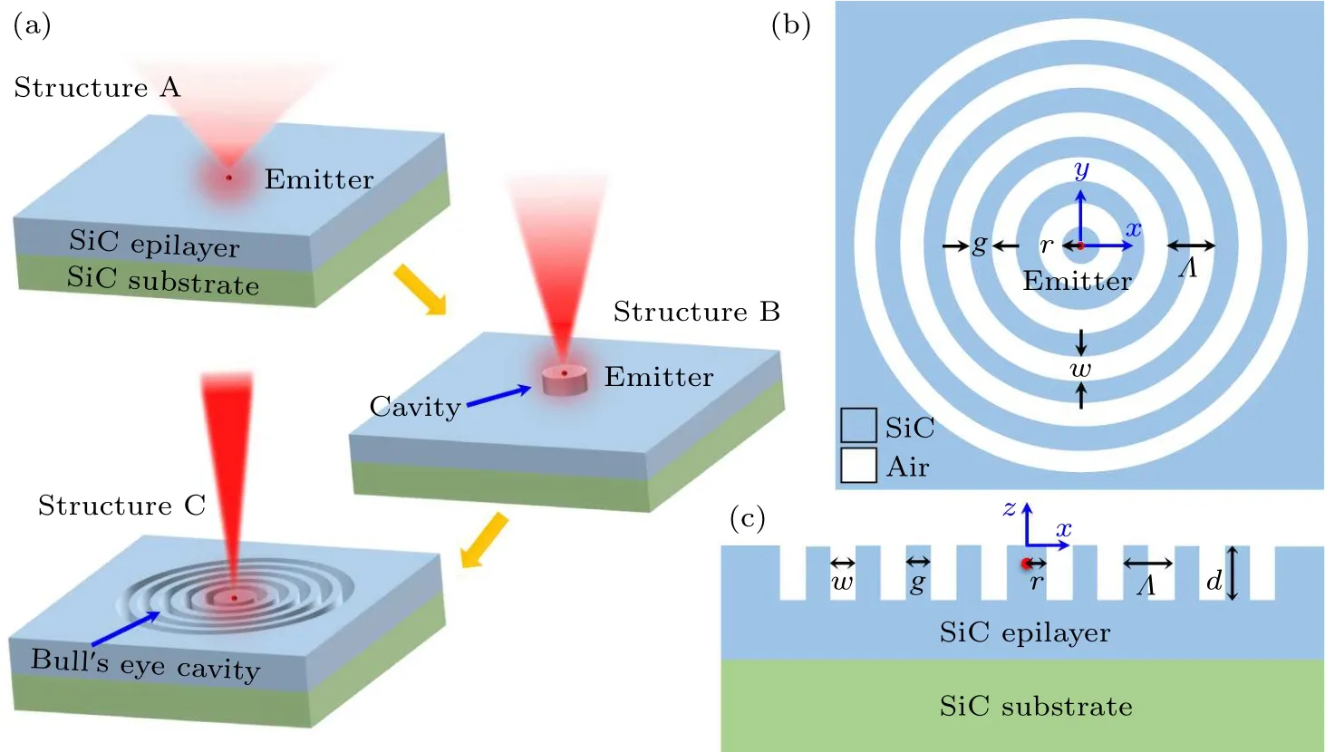
Fig. 1. Schematic diagram of the proposed SiC-based SPS. (a) Evolution of the SPS structure design from structure A to structure B and structure C. (b)Top-view and(c)cross-section schematics of structure C with N=4.
During the simulation, a dipole source was placed at the center (x=0,y=0,z=-300 nm) with a depth of 300 nm beneath the top surface of the SiC epilayers. This dipole depth is optimal for achieving a high Purcell factor based on simulations (not shown). The transverse magnetic (TM) and transverse electric(TE)modes are defined for the magnetic or electric fields parallel to the slab(i.e.,xy-plane),respectively.Considering the dipole orientation can be selected as any of horizontal and vertical directions, we calculated both polarizations individually and the results were similar. Thus, only the case of horizontally oriented dipole was studied in this letter. To ensure an efficient vertical light extraction at 600 nm,FDTD method was employed to optimize all the structural parameters. Although these parameters are interlinked in fact and there is a trade-off between them, we carry out separate analyses since they allow us to distinguish different influences or mechanisms among the central cavity and the surrounding grating. For simplicity,we assumeg=w. The collection efficiency(CE)can be calculated as the ratio of photons collected by an objective lens with a numerical aperture(NA)to all photons emitted into far field.[17]The formula reads as

where far field electric fieldEis a function of the direction cosines(ux,uy), andθNAis the half-angle corresponding to a given NA.
3. Results and discussion
One important figure of merit of the device performance is radiative decay rate, which can be optimized for structures B and C by sweeping the geometrical parameters as shown in Fig. 2. For structure B, when sweeping the radius (r) from 100 nm to 500 nm by fixing the height of the cylinder cavity(d)to be 500 nm,a series of maxima in intensity are observed atr=13, 260, 375 nm,etc., as shown in Fig.2(a)due to the lateral mode resonances. Considering a compact device layout,we preferr=13 nm for structure B.It can be seen from Fig. 2(b) that the radiative rate also depends on the height of the cylinder cavity(d)in structure B.For the emission wavelength of 600 nm, the value ofdin the range of 450 nm–550 nm is favorable to ensure a high radiative rate. Whilst for structure C, the suitable value range ofdfor the same emission wavelength is from 690 nm to 720 nm (Fig. 2(c)). For simplicity,we fixdat 500 nm for structure B and 700 nm for structure C,respectively. Although deeper etching might also support a high radiative rate due to the multiple longitudinal modes in the Fabry–P´erot cavity,it will lead to tricky fabrication process for a larger depth ofd.
When introducing a CBG antenna, the resonance modes exhibit more sensitive to the cylinder radius due to the enhancedQ-factors,which can be seen clearly by comparing the data between Figs. 2(a) and 2(d). Therefore, a more precise control of the cylinder size is required to make sure a cavity resonance for the color center in structure C.To ensure the device with a compact layout and also a feasible fabrication,we chooser=140 nm for structure C. As the period length (Λ)of the CBG increases from 100 nm to 700 nm(see Fig.2(e)),the calculated radiative rate of structure C varies periodically and its maxima occurs when Bragg conditions are satisfied,in which an efficient coupling occurs between the same forward and backward modes in a periodic single-mode guided wave structure. According to the coupled-mode theory, the Bragg condition can be written asmλ=2neffΛ, wheremis the diffraction order andneffis the SiC slab TE mode effective index. We may chooseΛ=18, 315, or 455 nm for structure C, corresponding tom= 1, 2, or 3 that satisfies the 1st, 2nd,or 3rd Bragg condition. Although the refraction index of SiC tends to be high,the mode number can be small owing to the subwavelength size of the structure.

Fig. 2. Dependence of the normalized radiative decay rate spectra on (a) radius and (b) height of the cylinder cavity in structure B. Dependence of the normalized radiative decay rate spectra on(c)trench depth,(d)cylinder radius,and(e)grating period of structure C.
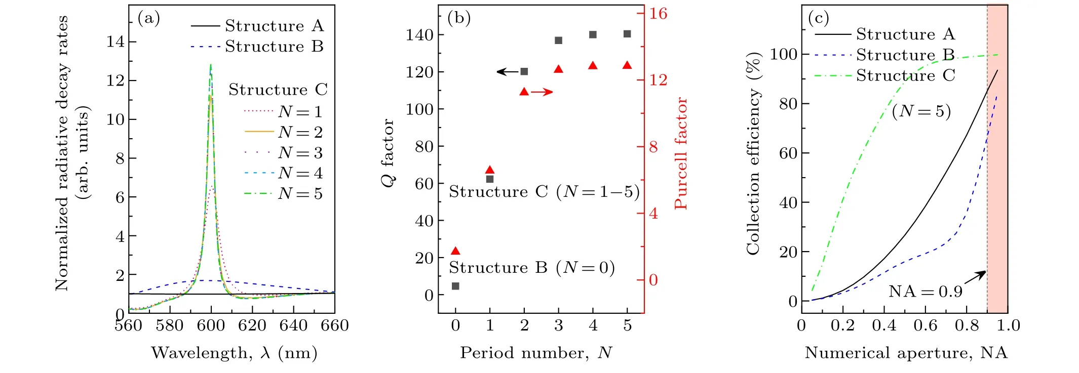
Fig.3. (a)The normalized radiative decay rate spectra of structures A,B,and C with various period number N. (b)The simulated values of Q and FP with different N. Practically,N=0 represents the case of structure B.(c)The calculated collection efficiency of structures A,B,and C with various NA.
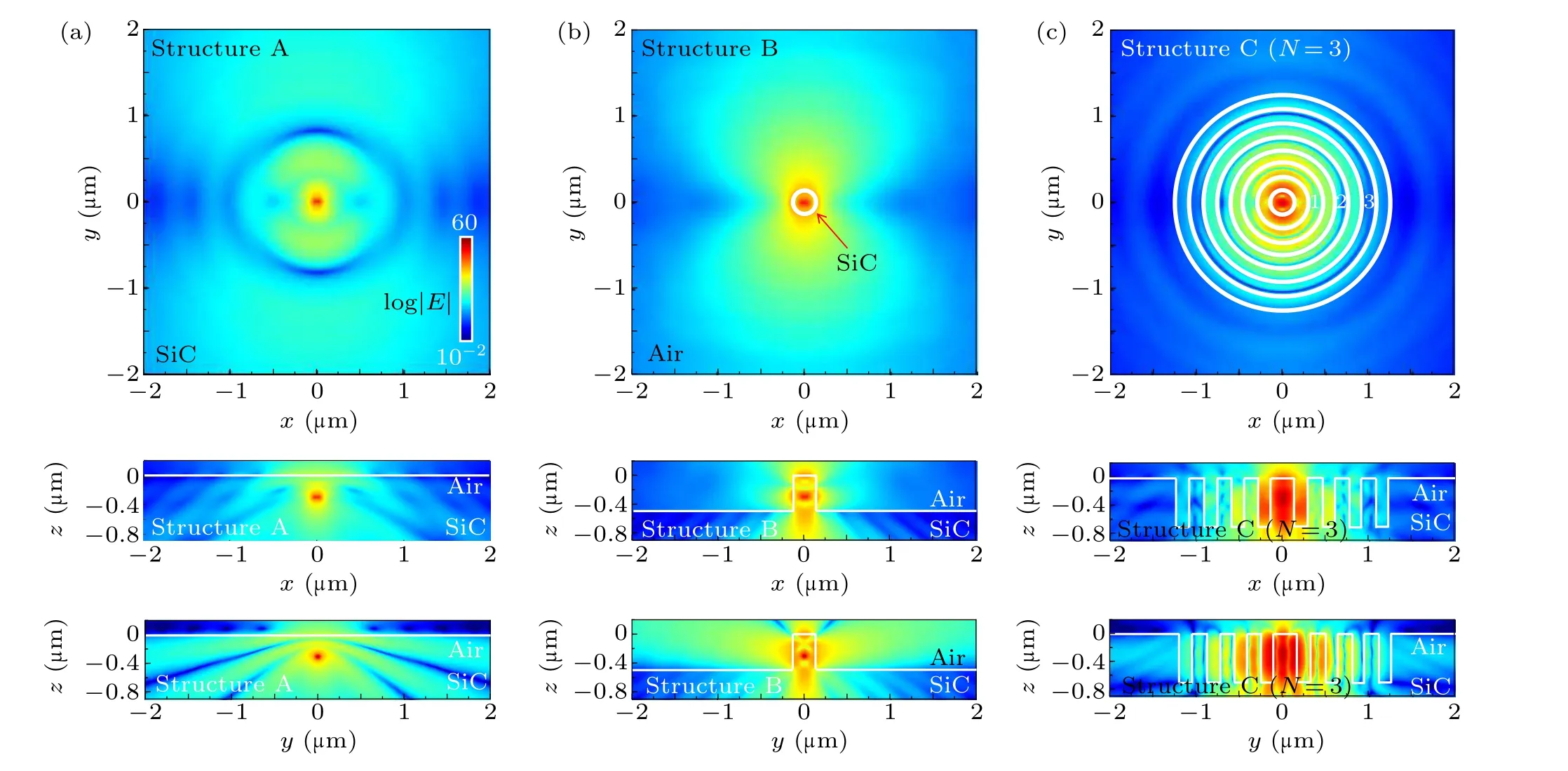
Fig. 4. The simulated near-field (|E|) (logarithmic scale) distributions in (a) structure A, (b) structure B (r=140 nm), and (c) structure C (r=140 nm,d=700 nm,Λ =315 nm,N=3)in the xy,xz,and yz planes at the wavelength of 600 nm.
As described above,the Purcell factor(FP)is proportional to the ratio ofQandVm, which can be calculated based on FDTD simulations. Figure 3(a)displays the calculated radiative decay rate spectra of structures A–C. During the simulation,the light source was set as an electric dipole at the color center with a unit amplitude of electric field and the orientation aligned along they-axis direction, exciting only TE slab waves.The groove numberNin structure C is varied from 1 to 5. As shown in Fig.3(a),the radiative decay rates of structure A are quite low and no peaks can be observed throughout entire wavelength range from 560 nm to 660 nm,which means a heavy emission loss in the block material. In the case of structure B,a broad peak around 600 nm appears indicating a lowQ-factor.As discussed above,introducing CBG is a promising way to significantly enhance the intensity of the photon emission, which can be seen from the higher and narrower peaks in the spectra of structure C.As compared to structure A,the radiative decay rate at 600 nm can be enhanced by 12.8 times in structure C (N ≥3). For clarity, we extract the FWHM values from the radiative decay rate spectra and calculatedQfactor as shown in Fig. 3(b). It shows a remarkable increase ofQ-factor which reaches saturation when the period numberNexceeds 2. By using the FDTD simulation, the mode volumeVmof each dielectric cavity can be calculated and then the Purcell factorFPcan be obtained according to Eq.(1). When compared to structure B, theQ-factor is increased by~30.5 times in structure C withN ≥3. The mode volumeVmis 0.21(λ/n)3in structure B whilst increases up to~0.82 (λ/n)3in structure C,where the refractive index of SiC is considered asn=2.64 at the wavelength of 600 nm.[18]Eventually, the Purcell factor(FP)in structure C is about 7.6 times as high as structure B.As shown in Fig.3(c),the collection efficiency as a function of the NA is theoretically enhanced from structure A to structure C (N=5), which is mainly contributed by the improved emission directionality. However, the CE of structure B is the lowest especially when NA less than 0.7, which might be due to the scattering by the central cylinder.
To further understand the Purcell factor enhancement,we plot out the electromagnetic field configurations in logarithmic scale at the wavelength of 600 nm in structures A,B,and C (withN=3) in Fig. 4. The light source was set as same as Fig.3. Apparently,the electromagnetic field extends over a relatively large area in bulk SiC(i.e.structure A).In structure B, the emission starts to be concentrated by the micrometerscale resonator due to Fabry–P´erot resonance, while the resonant TE mode becomes leaky and features the capability of interacting with outside owing to the small geometric size. By coupling with CBG in structure C, the electromagnetic field is squeezed into the area of Bull’s eye rings whenN ≥3, indicating that our designed structure has been optimized for a Purcell factor as high as possible. As shown in Fig. 4(c), a lower bound of spatial field distribution is found with two secondary maximum pots appearing on the sidewall of the central cylinder. This indicates a larger mode volume that has been discussed above. As explained in Ref.[19],vertical light scattering at the CBG antenna in structure C is partial,so that the 2nd-order Bragg reflections towards the central cavity lead to a vertically leaky cavity resonance as shown in Fig.4(c). At the SiC-air interfaces of trenches,the large index contrast leads to strong reflections and out-of-slab-plane scattering, which are evidenced by the strong field concentration at the Bull’s eye center and a fast field decay in the couple of trenches from the center.[19]It interprets the larger enhancement of field intensity in structure C,eventually higherQ-factors and Purcell factors.

Fig.5. (a)–(c)Simulated far-field polar plot(|E|2)of structures A–C at λ =600 nm. (d)Normalized electric field distribution(|E|)along the propagating direction in xz-plane of structure C(left),and along the dotted gray line for changed period length(right). (e)The dependence of the maximum E intensity at the focal point on the period number.
The directionality of emission can be quantified by examining the angular distribution of the emitted light in farfield(see Figs.5(a)–5(c)). During the simulation,the dipole source was set as same as Fig. 3. Comparing the results obtained from structure A, the simulated emission intensities of structures B and C are enhanced by one or two orders owing to the resonance. However,the directionality of structure B remains poor with an emission angle of about 50°, which is consisted with the low collection efficiency.Importantly,an obvious improvement of far-field directionality can be seen from structure C, clearly indicating that the Bull’s eye cavity not only supplies a higherQ-factor but also strongly governs the propagation direction of light emitted from the center cylinder. To clearly illustrate the physical mechanism of the light-focusing functionality, we calculated the electric field distribution of structure C in thexz-plane at the wavelength of 600 nm (see the left image of Fig.5(d)). A bright focal spot can be seen atz=5 μm in free space. The focusing process can be attributed to the scattering of the emitted light at different positions of the grooves and the corresponding in phase field superposition due to the constructive interference on the optical axis.[20]In the simulation, we additionally included a linear profile monitor for structure C(i.e.,the dotted gray line shown in the left image of Fig.5(d)).This allowed us to examine theE-field crosssectional profile cut along thezaxis. As shown in the right image of Fig. 5(d), when the period (Λ) varies from 100 nm to 600 nm with fixed parameters ofd=70 nm,r=140 nm,andN=5, the focal point (where the maximumEintensity occurs)moves gradually. It can be understood that the period length decides the groove locations where the scattering or reflection will happen. The variation leads to the change of the near field distribution, and ultimately influences the intensity and location of the focal spot. Confirmed by the calculated far-field distributions shown in Fig. 5(c), the CBG antenna withΛ=315 nm acts as a near-field focusing lens to a small degree (~15°), which can concentrate more emission in the vertical direction and bring excellent far-field directionality.This is also verified by the increase of CE. It was found that the directionality depends on the period numberNas shown in Fig. 5(e). WhenNincreases, theE-field at the focal point is gradually enhanced due to an improved focusing capability of CBGs and then saturates whenN ≥6 where the Bragg scattering is balanced by the leakage of light in the plane of grating.AlthoughN=3 is enough to reach the saturation value ofQorFP,the period number still needs to be increased up to 6 for an optimal directionality.
4. Conclusion and perspectives
In summary, we demonstrated the improvement of photon emission and beam directionality in an SiC-based singlephoton source by employing circular Bragg gratings coupled with a cylinder cavity, in which a resonance cavity mode at 600 nm with Bragg reflection occurred. The structural parameters,including cylinder radius,grating period,and trench depth,etc., are identified and optimized based on FDTD numerical simulations. For quantum light emitters, Purcell enhancement, and convergent angular distribution of the emitted light in far field are achieved, which indicated that this structure allows for efficient transmission of light in SiC.The proposed structure design plays a vital role in quantum electrodynamics and could have potential in application of highperformance quantum light sources.
Acknowledgments
Project supported by the National Natural Science Foundation of China(Grant Nos.91850112,61774081,62004099,and 61921005), in part by Shenzhen Fundamental Research Program (Grant Nos. JCYJ20180307163240991 and JCYJ20180307154632609),in part by the State Key Research and Development Project of Jiangsu Province, China (Grant No. BE2018115), in part by the Natural Science Foundation of Jiangsu Province, China(Grant No.BK20201253), in part by the State Key Research and Development Project of Guangdong Province, China (Grant No. 2020B010174002),and in part by Strategic Priority Research Program of Chinese Academy of Sciences(Grant No.XDB43020500).
猜你喜欢
美与时代·美术学刊(2022年3期)2022-04-27
瞭望东方周刊(2022年5期)2022-03-17
故事会(2022年1期)2022-01-06
华人时刊(2021年17期)2021-11-12
水上消防(2021年4期)2021-11-05
重庆与世界(2020年12期)2020-12-23
老友(2019年9期)2019-10-23
金沙江文艺(2019年7期)2019-07-29
金沙江文艺(2017年4期)2017-03-31
故事会(2016年24期)2016-12-20
- Chinese Physics B的其它文章
- Formation of high-density cold molecules via electromagnetic trap
- Dynamics of molecular alignment steered by a few-cycle terahertz laser pulse
- Terahertz spectroscopy and lattice vibrational analysis of pararealgar and orpiment
- Molecule opacity study on low-lying states of CS
- Finite-time Mittag–Leffler synchronization of fractional-order complex-valued memristive neural networks with time delay
- Ultrafast Coulomb explosion imaging of molecules and molecular clusters