
Fluid simulation of the effect of a dielectric window with high temperature on plasma parameters in inductively coupled plasma
2023-03-15 00:54NaLI李娜DaomanHAN韩道满QuanzhiZHANG张权治XuhuiLIU刘旭辉YingjieWANG王英杰andYounianWANG王友年
Plasma Science and Technology 2023年3期
Na LI (李娜), Daoman HAN (韩道满), Quanzhi ZHANG (张权治),*,Xuhui LIU(刘旭辉),*,Yingjie WANG(王英杰) and Younian WANG(王友年)
1 Key Laboratory of Materials Modification by Laser, Ion, and Electron Beams (Ministry of Education),School of Physics, Dalian University of Technology, Dalian 116024, People’s Republic of China
2Lab of Advanced Space Propulsion and Beijing Engineering Research Center of Efficient and Green Aerospace Propulsion Technology, Beijing Institute of Control Engineering, Beijing 100190, People’s Republic of China
Abstract To maintain the high-density plasma source in inductively coupled plasma (ICP), very high radiofrequency power is often delivered to the antenna, which can heat the dielectric windows near the antenna to high temperature.This high temperature can modulate the plasma characteristics to a large degree.We thus study the effect of dielectric window temperature on plasma parameters in two different ICP structures based on COMSOL software.The distributions of various plasma species are examined at different dielectric window temperatures.The concentration of neutral gas is found to be largely modulated at high dielectric window temperature,which further affects the electron collision probability with neutrals and the electron temperature.However,the electron density profiles are barely affected by the dielectric window temperature, which is mainly concentrated at the center of the reactor due to the fixed power input and pressure.
Keywords: fluid simulation, metastable argon, dielectric window temperature, inductively coupled plasma
1.Introduction
Inductively coupled plasma (ICP) driven at radiofrequency(RF) is widely used in various applications, such as nanofabrication[1-3]in the semiconductor industry,neutral beam injection[4,5]in nuclear fusion(serves as the ion source[6]),and RF ion thrusters in satellite propulsion [7-9].ICPs are generally characterized by many advantages: the electron heating rate is high due to the circular inductive field induced by RF power; there are no electrodes inside the ICP source and the plasma sheath can be ignored,which reduces the loss of plasma on the sidewall; and the magnetic field induced by the RF antenna may confine the electrons to a degree, which leads to more collisions between the electrons and the background gas.These advantages allow one to sustain very high plasma density and ion flux in the ICP discharge, which is strongly desired for certain processes as it determines the processing efficiency.
In an ICP source, the input RF power is coupled to the discharge reactor through the coil antenna configurations by inducing an electromagnetic field in the reactor.There are two main structures of typical ICP sources, depending on the geometry of the reactor design [10].One is to wrap RF coils around the side of the cylindrical discharge reactor, commonly known as a spiral cylindrical coil.The other is to place the coils at the top of the reactor, commonly known as a planar coil.The two different structural models are used in different processes.An axial magnetic field and a circular inductive electric field can be induced by the RF antenna current.The circular electric field can then heat the electrons to experience collisions with neutrals, sustaining the discharge.The corresponding heating mode is called inductive power coupling mode, which is often referred to as H mode.In contrast, an electrostatic field between the antenna and grounded reactor wall can also be induced when high voltage is applied to the RF antenna, which may contribute to power deposition as well.The corresponding heating mode is called capacitive power coupling mode (E mode).It has been a controversial issue whether the discharge is sustained by the inductive field(H mode)or the electrostatic field(E mode),as the plasma characteristics are distinct, and E-H mode transition is a characteristic feature of ICP discharge.Hence, E-H mode transition [11-13], and the hysteresis of plasma parameters [14] (plasma density, average electron energy and so on) during the E-H mode transition, have been studied considerably under various parameters.It is well known that both the inductive and electrostatic field can be the dominant heating mechanism to sustain the discharge,depending on the discharge conditions.The E-H mode transition is sensitive to the applied power,the E mode usually presents at low power input with a relatively low plasma density, and the discharge is dominated by the H mode when the power increases.Therefore, the discharge generally experiences E-H mode transition with rising applied power, during which the large sheath in the E mode attracts ions to bombard the sidewall and dielectric window (isolating the coil and discharge reactor), causing damage and heating to the dielectric window.Meanwhile, very high RF power (up to several kW) is often delivered to the antenna to maintain the high-density plasma source in H mode,and the RF coils and the dielectric window can be heated to a very high temperature.This high temperature of the dielectric window could inversely affect the plasma characteristics to a large degree, which has not been examined yet to our best knowledge.
In addition, plasma enhanced chemical vapor deposition(PECVD)[15,16]has been widely used in the semiconductor industry to produce nanosheets on a substrate, in which the substrate is generally heated up to 700 °C [17].Common sources[15]of plasma generation include direct current(DC)PECVD, microwave PECVD [18, 19] and inductively coupled PECVD.In such processing, the plasma is formed locally through ionized gas,and the activity of the plasma and the heated substrate are used to promote the chemical reaction,so as to prepare the required nanosheets.Manish Kumar et al[20]studied the effects of substrate temperature and DC bias on plasma and nanosheet characteristics in the process of preparing graphene nanosheets, and analyzed the distribution and variation of plasma at different substrate temperatures with or without DC bias, as well as the change in thin film thickness with different physical quantities.Their results reveal that the electron density decreases and the film thickens with increasing substrate temperature, and the film becomes more uniform after applying bias voltage.However, in practical applications of inductively coupled PECVD, the dielectric window between the plasma and antenna coil is often used as an extra heating source to heat the internal gas(increasing the chemical activity).It is thus meaningful to study the influence of dielectric window temperature on plasma parameters, because temperature is an important influencing factor in PECVD processing.
In this work, we perform corresponding simulations to investigate the influence of dielectric window temperature on plasma behaviors in both planar coil and cylindrical coil configuration,and their combined configuration,in argon ICP discharge.The two-dimensional (2D) fluid model employed is described in detail in section 2.The effect of the dielectric window temperature on the plasma characteristics is discussed in section 3.Finally, the main conclusion is summarized in section 4.
2.Simulation model
In this work, we use COMSOL multi-physics simulation software to simulate the 2D axisymmetric ICP source model,including the plasma, coil group, and dielectric window.The detailed dimensions of the first ICP model are shown in figure 1(a),and the structure of the second ICP model is given in figure 2(a).The first model mainly uses the planar coil to maintain discharge,and the second model realizes double-coil discharge by adding an extra set of cylindrical coils around the reactor of the first model.The planar coils and cylindrical coils are placed on a dielectric window, and the walls are grounded.RF power is applied to the coils to generate plasma.The radius of the discharge reactor is 0.3 m and the height is 0.4 m, the initial temperature of the reactor is assumed to be 300 K,the gas temperature at the inlet is set at 300 K, the gas inlet is at the axis with a radius of 0.03 m,the gas mass flow is 100 ml min-1, and the gas outlet is at the sidewall of the reactor.The discharge is assumed to be with laminar flow because of the low gas velocity.As a result,the modules of plasma, magnetic field, laminar flow, and fluid heat transfer are coupled in this model.The corresponding modeling process mainly involves the solutions of several important conservation equations,such as the electromagnetic field equation, particle conservation equations, momentum conservation equations, the Navier-Stokes equation of the neutral gas,the heat transfer equation of the neutral gas and so on.Argon is used as the working gas and we thus consider four species; the corresponding reactions of these species are listed in table 1.Moreover, the surface reactions are also significant, as shown in table 2.The rate coefficients of reactions 1-5 in table 1 were calculated using collision cross sections [21]; the equation is:
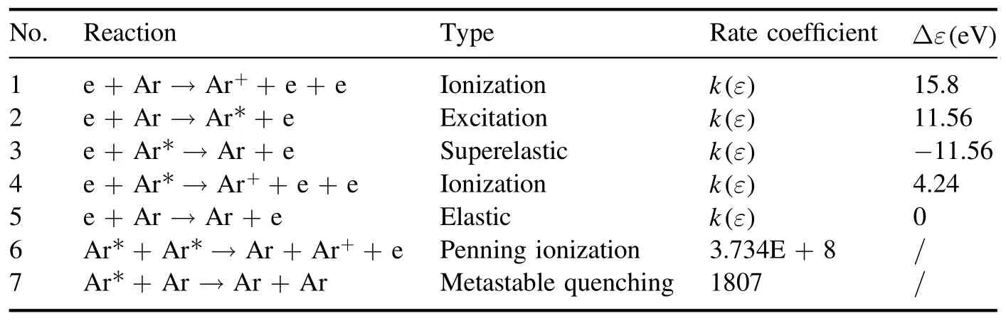
Table 1.Important reactions in this model [21, 22].

Figure 1.Schematic and mesh division of single-coil ICP.(a)Reactor structure, (b) mesh.
The rate coefficients of the heavy species reactions are given as constants [21].
2.1.Fluid equations
In the fluid model, the continuity equations, the energy conservation equation and the drift-diffusion equation are solved to calculate the electron density and the electron energy.The equations are given as [22-24]:
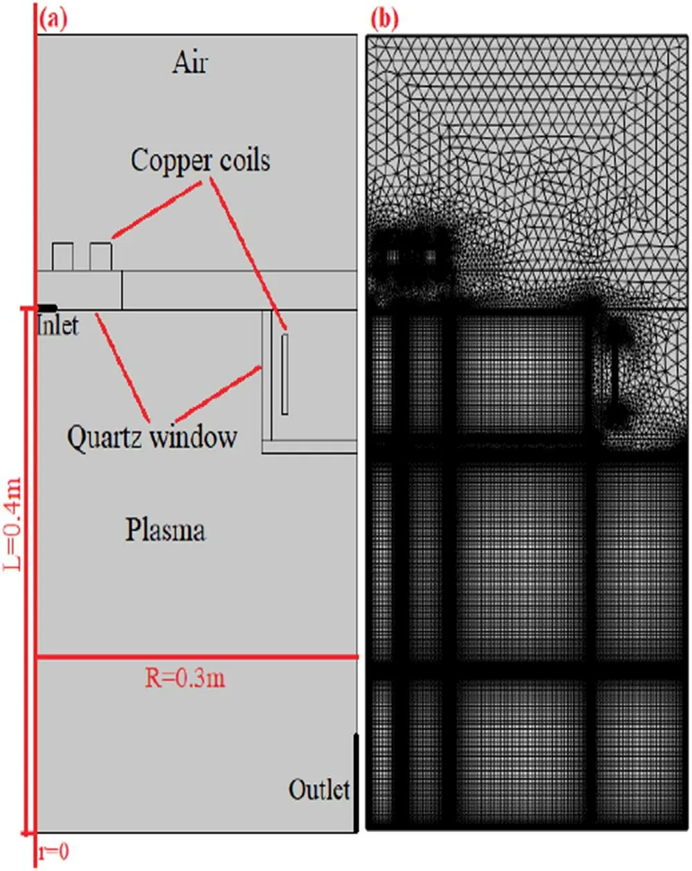
Figure 2.Schematic and mesh division of double-coil ICP.(a)Reactor structure, (b) mesh.
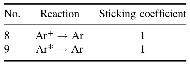
Table 2.Surface reactions in this model [21, 22].
whereneis the electron density,Teis the electron temperature,μeandDeare the mobility and the diffusivity of electrons,and ΓeandΓεare the flux terms for the electron and electron energy respectively.Esis the electrostatic field generated by the motion of space charges.Reis the electron source term due to the collisions listed in table 1.Pindis the total power deposition andSenis the energy loss term because of inelastic collisions between electrons and neutral species.
The electron diffusivityDeand the electron mobilityμeare calculated by [25]:
whereKBis the Boltzmann constant,meis the electron mass,νeffis the equivalent collision frequency,mνis the momentum transfer collision frequency,νstocis the stochastic collision frequency,is the electron thermal velocity,δeffis abnormal skin depth,ωis the radio angular frequency,ωpeis the plasma frequency,Nnis the target particle density, andk(Te)is the rate coefficient corresponding to the elastic collision.
The continuity equation of the ions and the drift-diffusion approximation are [26]:
The mobility and diffusivity of the ions are calculated according to the following formulas [25]:
For the metastable species, the transport equations are:
where Γnis the flux,Rnis the particle source, andDnis the diffusion coefficient based on kinetic gas theory [27, 28].
The electrostatic field is calculated based on Poisson’s equation:
whereϕis the electric potential,andε0andεrare the vacuum permittivity and the relative permittivity of materials.
2.2.Electromagnetic field equations
In ICP discharge, the RF coils generate a magnetic field that induces a circular electric field.The electromagnetic field equation can be derived based on the Maxwell equations as:
whereAis the magnetic potential vector, j is the imaginary unit,ωis the RF angular frequency,μ0andμris the vacuum magnetic permeability and the relative permeability of specific media,Jcoilis the applied coil current, andσis the plasma electric conductivity.
The total power absorptionPindis described as:
whereJis the conduction current density,E*is the complex conjugate of the circular electric field,andPindis the inductive heating density, i.e.the power deposited into the plasma.
2.3.Neutral gas equations
The background neutral gas density has an important influence on the generation of plasmas and the collisions between particles.We use the following equations to describe quasineutral gases in this model [22]:
whereρis the mass density of the neutral particles,Nis the particle density,uis the gas velocity,μis the viscosity coefficient,Tis the gas temperature,Fis the volume-force,which is equal to zero,andKBis the Boltzmann constant.The boundary conditions at the inlet and outlet are set as mass inlet and pressure outlet type,and no slip boundary conditions are set on the wall, i.e.u=0.
The heat transfer equations of neutral particles are expressed as follows [29]:
whereCP= 20.785m ol · K)is the heat capacity for the temperature range studied here, which is calculated by COMSOL software based on [30],qis the heat flux vector,the constant of proportionality,Qis the heat source, andis the thermal conductivity [31],in whichMis the molecular weight (unit: kg/mol),ηis the dynamic viscosity, andRg= 8.314 J /(m ol · K)is the ideal gas constant.
2.4.Boundary conditions
As the secondary electron emissions are neglected, the boundary conditions for the electron flux Γeand the electronic energy flux Γεare given as:
wherereis the electron reflection coefficient, which is set to 0.2;nis the normal perpendicular to the wall.
The boundary conditions for ion flux Γiare
wherevth,iis the thermal velocity of ions.
The boundary conditions for metastable specie flux Γnare
wherevth,nis the thermal velocity of neutrals.
In this work, the ion temperature is assumed to be the background gas temperature, so only the particle balance equation and momentum conservation equation for ions are considered.
For the boundary conditions of solving the background gas, the gas flux at the inlet is set as 100 ml min-1, the pressure at the outlet is set as 0 Pa, and a non-slip boundary(u=0) on the sidewall is set.In the heat transfer module,apart from the dielectric window, the wall temperature is set to room temperature (300 K).
Finally, other boundary conditions on the chamber walls include:the chamber is grounded(V=0),secondary electron emission is ignored, and the thermal emission flux and mean thermionic energy are set to be zero.
In COMSOL multi-physics simulation software, all the equations are discretized based on a finite element logarithm.In order to obtain more accurate solutions,the regions of the coils and discharge reactor adopt a mapping mesh, and a triangular mesh is used in the air domain and dielectric window.The mesh divisions of the two models are shown in figures 1(b)and 2(b).
3.Results and discussion
3.1.Single-coil ICP model
In this sub-section,the effects of dielectric window temperature on the discharge characteristics in a planar-coil ICP reactor(shown in figure 1)are examined.The total power of the coils is set to be 2000 W,the discharge frequency is 13.56 MHz,and the background reference pressure in the laminar flow module is 0.02 Torr.The temperature of the dielectric window is tunable(300 K,500 K,700 K and 900 K),and the gas temperature,gas density, metastable argon density, electron density and electron temperature are addressed.
The distributions of neutral gas temperature at various dielectric window temperatures(300 K,500 K,700 K,900 K)are shown in figures 3(a)-(d).It can be seen from figure 3(a)that,when the dielectric window temperature is 300 K,which is the same as the initial temperature of the reactor wall, the temperature of neutral gas in the bulk plasma region is the highest.This is mainly due to drastic collisions between electrons, ions and background gas here, which transfer energy to the background gas and heat neutral gas.When the temperature of the dielectric window rises to 500 K(figure 3(b)), not only does the collision transfer energy to neutral gas, but also causes the dielectric window to be regarded as a heat source, which obviously heats the neutral gas under the dielectric window.Figure 4 presents the axial distributions of neutral gas temperature at r=150 mm at different dielectric window temperatures.As can be seen,the neutral gas temperature in the chamber is mostly around 300 K at a 300 K dielectric window temperature.In contrast,the neutral gas within 150 mm distance from the dielectric window can be significantly heated when the dielectric window temperature increases.This may further modulate the plasma characteristics in the vicinity.
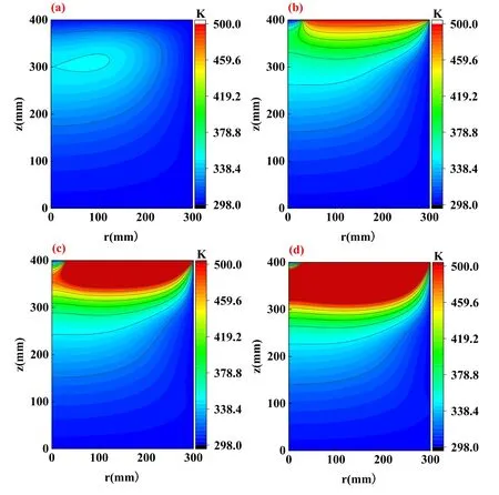
Figure 3.Influence of dielectric window temperature on gas temperature in single-coil ICP model.(a) 300 K, (b) 500 K,(c) 700 K, (d) 900 K.
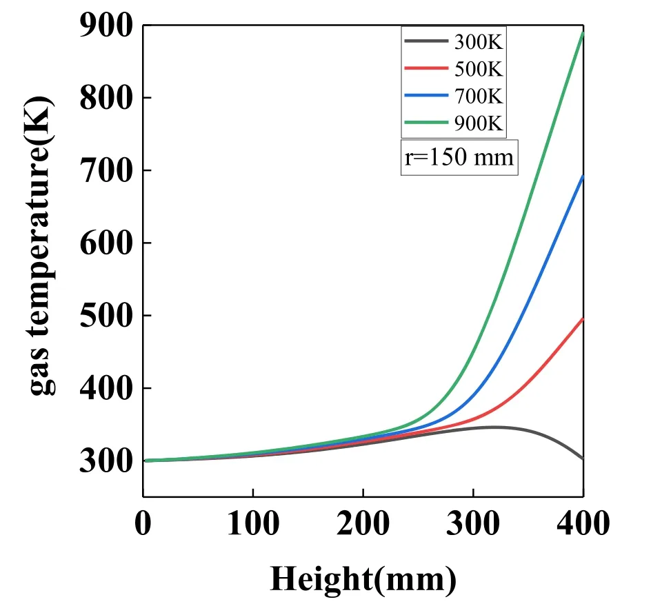
Figure 4.Influence of dielectric window temperature on gas temperature along the axial direction in the single-coil ICP model(r=150 mm).
Figures 5(a)-(d)further present the distributions of argon density when the temperatures of the dielectric window are 300 K, 500 K, 700 K and 900 K, respectively.As seen in figure 5(a),when the dielectric window temperature is 300 K,the argon density at the gas inlet is the highest, followed by that at the sidewall, whereas it has the lowest density in the bulk plasma region(about 300 mm in the central axis).When the temperature of the dielectric window goes up to 500 K(figure 5(b)), the neutral gas density under the dielectric window becomes the lowest, while the density at the plasma diffusion zone and sidewall of the reactor slightly increases,indicating that the argon tends to diffuse toward the places with low temperature.Similarly, the argon density profiles in figures 5(c)and(d)are similar to that in figure 5(b),but with more intense changes.This is due to the ideal gas equationP=NKBT(where P is the reactor pressure, N is the particle number density,KBis Boltzmann constant, and T is the gas temperature): when the gas pressure remains unchanged, an increase in neutral gas temperature results in a decrease in the argon density.Therefore, the higher the dielectric window temperature is, the lower the argon density under the dielectric window becomes, while the argon density at the sidewall and bottom (~300 K) remains high.
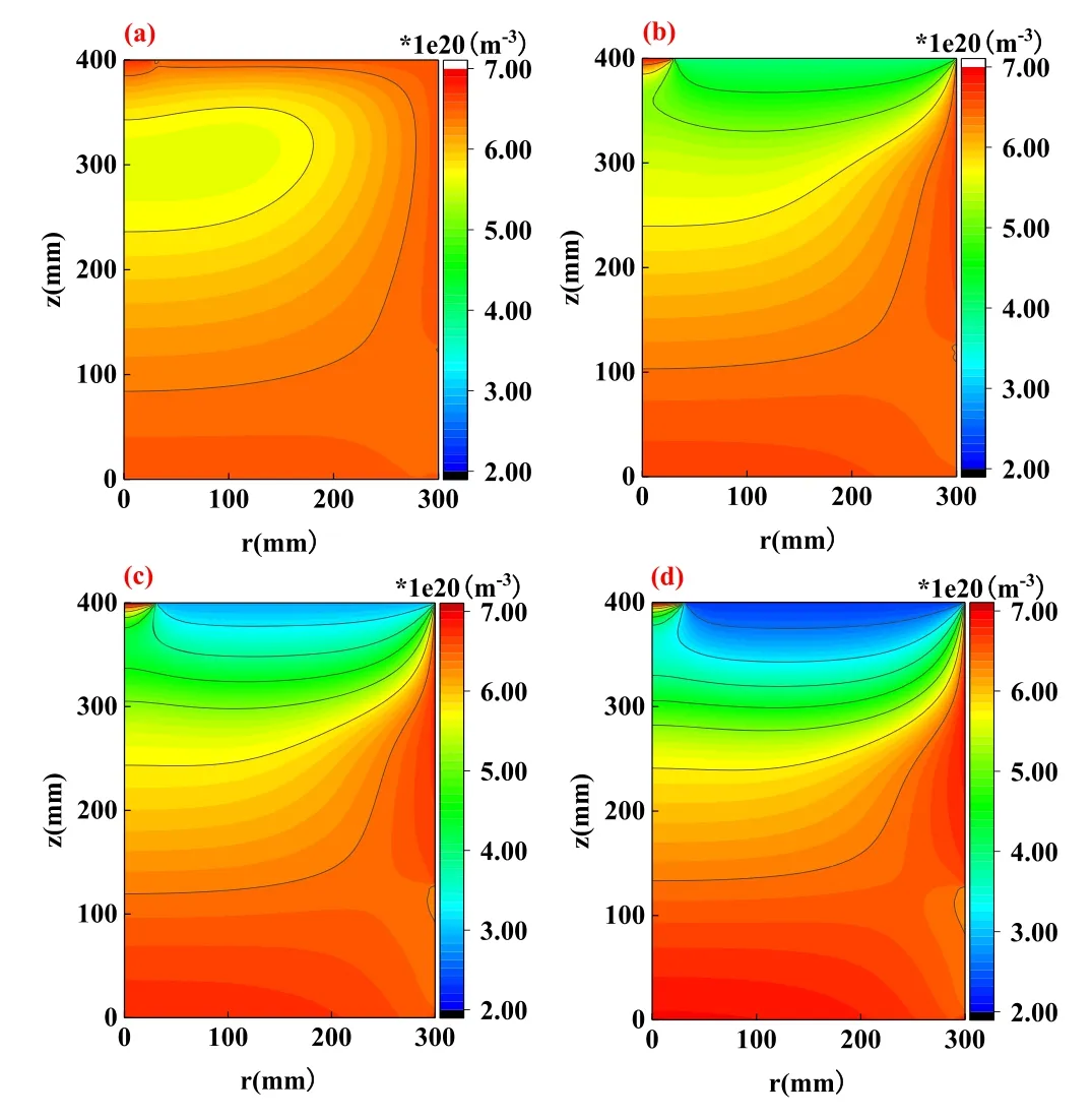
Figure 5.Influence of dielectric window temperature on neutral argon density in the single-coil ICP model.(a) 300 K, (b) 500 K,(c) 700 K, (d) 900 K.
Figures 6(a)-(d)show the distributions of metastable argon density at various temperatures of the dielectric window.Considering that the metastable argon (Ar*) is produced by the electron impact reaction (i.e.e +Ar →Ar* +e), and the electron energy is the highest under the dielectric window due to the strong electric field induced by the RF coils(shown below in figure 10),numerous metastable argon atoms are thus generated under the dielectric window, contributing the highest density here at 300 K (figure 6(a)).Figure 7 displays the axial distributions of metastable argon density at r=150 mm at different dielectric window temperatures.Within about 150 mm distance from the dielectric window, the variation of the dielectric window temperature has a significant modulation effect on the metastable argon density.When the dielectric window temperature is 300 K, the maximum metastable argon density appears near the dielectric window,whereas the metastable argon density significantly decreases in the vicinity of the dielectric window with increasing dielectric window temperature.On one hand,the reduced argon density under the dielectric window (shown in figure 5)induces less generation of metastable argon density.On the other hand,the metastable argon itself is also dominated by the ideal gas equationP=NKBT,i.e.the metastable argon density decreases as the temperature increases, making the metastable particles diffuse to the places with low temperature.
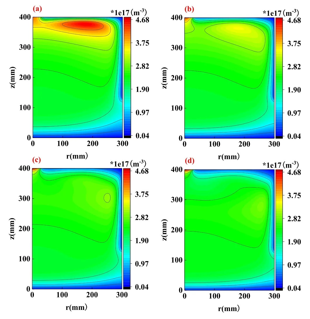
Figure 6.Influence of dielectric window temperature on metastable argon (Ar*) density in the single-coil ICP model.(a) 300 K,(b) 500 K, (c) 700 K, (d) 900 K.

Figure 7.Influence of dielectric window temperature on metastable argon (Ar*) density along the axial direction in the single-coil ICP model (r = 150 mm).
The distributions of electron density at different dielectric window temperatures are demonstrated in figures 8(a)-(d) to examine the behaviors of charged species.Figure 9 presents the radial distributions of electron density at z=250 mm at different dielectric window temperatures.The electron density distributions are quite similar at different temperatures of the dielectric window.The maximum electron density always appears at the center of the reactor, while the density value slightly changes with increasing dielectric window temperature.This is because the electron density is mainly controlled by the input power which is fixed in this work.Meanwhile, the background argon density is not affected much at the center of the reactor by the dielectric window temperature, and the ionization reaction rate thus remains almost constant.Figures 10(a)-(d)further present the distributions of electric field amplitude when the dielectric window temperatures are 300 K,500 K,700 K and 900 K,respectively.The electric field near the dielectric window is always the strongest with similar profiles at different dielectric window temperatures, which corresponds to the fixed input power.The slight decrease in the electric field amplitude is induced by the slightly increased electron density(shown in figure 8)and plasma current,which inversely reduce the electric field in the plasma region generated by the coils.
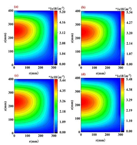
Figure 8.Influence of dielectric window temperature on electron density in the single-coil ICP model.(a)300 K,(b)500 K,(c)700 K,(d) 900 K.
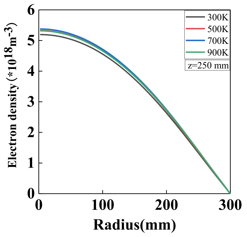
Figure 9.Influence of dielectric window temperature on electron density along the radial direction in the single-coil ICP model(z=250 mm).

Figure 10.Influence of dielectric window temperature on electric field in the single-coil ICP model.(a) 300 K, (b) 500 K, (c) 700 K,(d) 900 K.
The distributions of electron temperature are also demonstrated in figures 11(a)-(d) at various dielectric window temperatures.At 300 K, the high electron temperature is mainly located under the dielectric window,with the maximum value of 1.81 eV (shown in figure 11(a)).The maximum value of the electron temperature then slightly increases and the region with high electron temperature expands with increasing dielectric window temperature.This is because the background gas density and the collisions between electrons and neutral gas below the dielectric window decrease with increasing temperature of the dielectric window.Therefore,the electrons experience fewer collisions to lose energy at higher temperature of the dielectric window, after obtaining energy from the strong electric field(shown in figure 10) under the dielectric window.
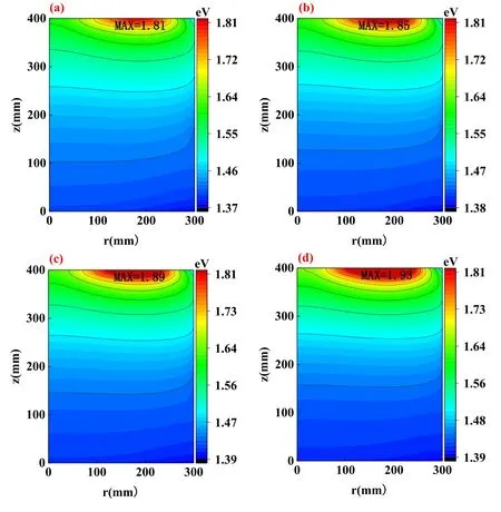
Figure 11.Influence of dielectric window temperature on electron temperature in the single-coil ICP model.(a) 300 K, (b) 500 K,(c) 700 K, (d) 900 K.
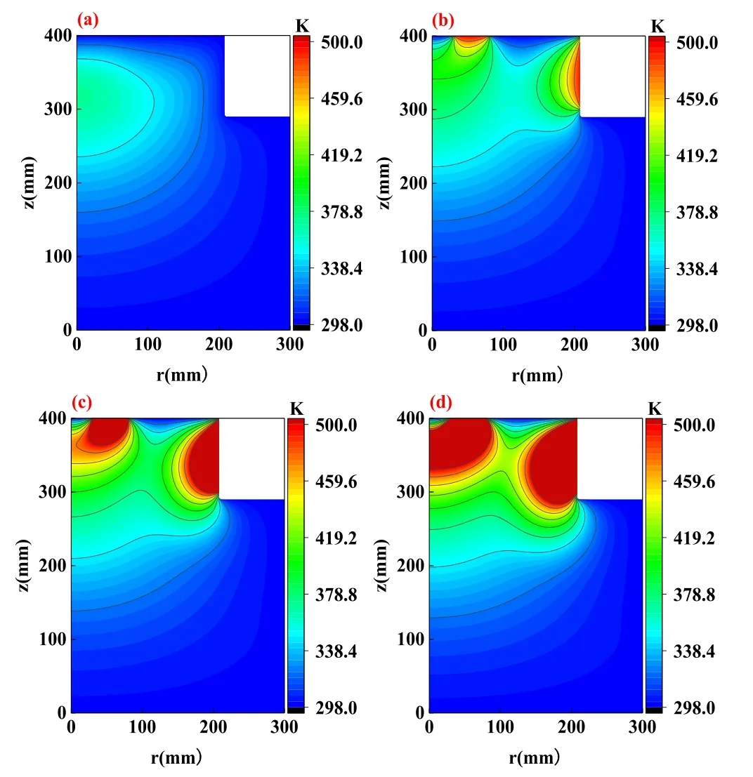
Figure 12.Influence of dielectric window temperature on gas temperature in the double-coil ICP model.(a) 300 K, (b) 500 K,(c) 700 K, (d) 900 K.
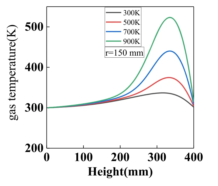
Figure 13.Influence of dielectric window temperature on gas temperature along the axial direction in the double-coil ICP model(r=150 mm).
3.2.Double-coil ICP model
The effects of dielectric window temperature on the discharge characteristics in a double-coil ICP reactor(shown in figure 2)are examined in this section.The RF power of both planar coils and cylindrical coils is set to be 1000 W, the discharge frequency is 13.56 MHz, and the background reference pressure in laminar flow module is 0.02 Torr.
Figure 12 presents the distributions of neutral gas temperature at different dielectric window temperatures.As shown in figure 12(a), the temperature of neutral gas is the highest in the bulk plasma region when the dielectric window temperature is 300 K.The main reason is that there are drastic collisions between electrons, ions and neutral gas in the bulk plasma region, which transfers energy to the neutral gas and induces high gas temperature.Figure 13 shows the axial distributions of neutral gas temperature at r=150 mm at different dielectric window temperatures in the second structure.Similar to figure 4, with increasing dielectric window temperature,the dielectric windows act as a heat source,which gradually increases the gas temperature in the vicinity.The higher the dielectric window temperature, the larger the affected area.
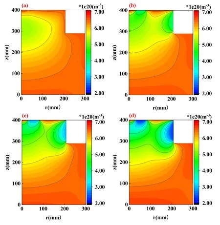
Figure 14.Influence of dielectric window temperature on neutral argon density in the double-coil ICP model.(a)300 K,(b)500 K,(c)700 K, (d) 900 K.

Figure 15.Influence of dielectric window temperature on metastable argon (Ar*) density in the double-coil ICP model.(a) 300 K,(b) 500 K, (c) 700 K, (d) 900 K.
We further demonstrate the distributions of argon density in figures 14(a)-(d),when the dielectric window temperatures are 300 K, 500 K, 700 K and 900 K.At 300 K, the argon density at the gas inlet is the highest, while it has very low density in the bulk plasma region (about 300 mm in the central axis).With increasing dielectric window temperature(figures 14(b)-(d)), the argon density near the dielectric window starts to decrease, and more argon gas tends to diffuse toward the bottom and sidewall (i.e.the regions with lower temperature).This is again due to the ideal gas equation P = NKBT,i.e.the higher temperature induces the lower neutral gas density when the pressure is fixed.Therefore, the argon density shown in figure 14 tends to have inverse profiles to the gas temperature distributions in figure 12.
Figures 15(a)-(d) display the comparisons of metastable argon density distributions at various dielectric window temperatures.Again, as the metastable argon (Ar*) is produced by the electron impact reaction (e +Ar →Ar* +e),the metastable argon mainly exists at the regions near the RF coils, because they have high electric field and electron temperature (see figure 19 below), at the dielectric window temperature of 300 K.Figure 16 exhibits the axial distributions of metastable argon density at r=150 mm at different dielectric window temperatures.The variation of the dielectric window temperature has a significant modulation effect on the metastable argon density.The metastable argon density significantly decreases in the vicinity of the dielectric window with increasing dielectric window temperature, i.e.both the background argon density and the metastable argon density are reduced near the dielectric window due to the ideal gas equation P = NKBT,forcing the metastable particles to diffuse toward the places with low temperature.Moreover,increasing the temperature of the neutral gas makes the thermal motion of neutral particles intense,and the following reactions are more likely to occur:Ar* +Ar* →Ar +Ar++e,Ar* +Ar →Ar +Ar,which further reduces the metastable argon density.Therefore, a higher dielectric window temperature induces a lower metastable argon density nearby the dielectric window.

Figure 16.Influence of dielectric window temperature on metastable argon density along the axial direction in the double-coil ICP model(r=150 mm).
We also plot the electron density in figure 17 at various dielectric window temperatures, to examine the effect of dielectric window temperature on the charged particles.Figure 18 displays the radial distributions of electron density at z=250 mm at different dielectric window temperatures.Similar to the conclusion drawn in figure 9, the maximum electron density is always located at the center of the reactor,presenting no big differences at various dielectric window temperatures,as the input power is fixed and the background gas density at the center is not affected.This again indicates that the dielectric window temperature has little direct effect on electron density(i.e.the distributions of charged particles).
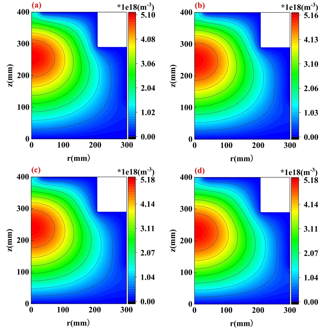
Figure 17.Influence of dielectric window temperature on electron density in the double-coil ICP model.(a) 300 K, (b) 500 K,(c) 700 K, (d) 900 K.

Figure 18.Influence of dielectric window temperature on electron density along the radial direction in the double-coil ICP model(z=250 mm).
To further explore the influences of dielectric window temperature on the charged particles,we plot the distributions of electron temperature in figure 19 at various dielectric window temperatures.It can be seen that the maximum electron temperature is mainly located close to the dielectric windows of planar coils and cylindrical coils,where the electric field induced by the RF coils is the strongest.With increasing dielectric window temperature, the region with high electron temperature obviously expands due to the reduced background gas density(shown in figure 14) and electron impact collision probability,near the dielectric windows.
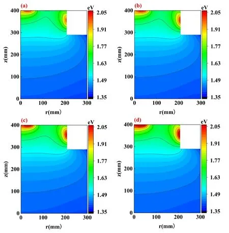
Figure 19.Influence of dielectric window temperature on electron temperature in the double-coil ICP model.(a) 300 K, (b) 500 K,(c) 700 K, (d) 900 K.
By comparing two ICP models,we can find that the effect of the dielectric window temperature on plasma parameters is quite similar.When the extra cylindrical coils are introduced,the two RF coils can work together to produce the plasma.The introduction of cylindrical coils slightly reduces the area of the planar coils, and changes the structures of the ICP reactors,which modulates the distributions of plasma species at the top of the reactor,while the profiles of plasma species stay quite similar at the bottom and sidewall.We expect that enlarged area of cylindrical coils could induce more differences and generate more influences on the plasma species at the reactor bottom,which will be examined in our future work.
4.Conclusions
In this work, COMSOL software is used to simulate two different ICP structures, and the influence of dielectric window temperature on plasma parameters (including background argon density,metastable argon atom density,electron density, electron temperature, gas temperature and so on) is examined.The results indicate that when the temperature of the dielectric window increases,the dielectric window can be regarded as a heat source, which heats the neutral gas in the regions near dielectric windows.According to the ideal gas equationP=NKBT,a higher temperature induces a lower neutral gas density when the pressure is fixed.Therefore,both the background argon density and the metastable argon density are obviously reduced near the dielectric window at high temperature, and the neutral gas tends to diffuse toward the bottom and sidewall(i.e.the regions with lower temperature).The reduced neutral gas density near the dielectric windows further decreases the electron impact collisions and inversely enhances the electron temperature.The electron density profiles are quite similar at different temperatures of the dielectric window,and the maximum electron density always appears at the center of the reactor with slight variations due to the fixed power input.The dielectric window with high temperature largely modulates the concentration of the neutral gas,but has almost no direct effect on the distribution of charged species.
Acknowledgments
This work is financially supported by National Natural Science Foundation of China(NSFC)(Nos.12105035 and 11935005),Guangdong Basic and Applied Basic Research Foundation(No.2021B1515120018), the Fundamental Research Funds for the Central Universities (No.DUT21TD104), and the Advanced Space Propulsion Laboratory of BICE and Beijing Engineering Research Center of Efficient and Green Aerospace Propulsion Technology (No.LabASP-2020-01).
猜你喜欢
Plasma Science and Technology(2022年11期)2022-11-17
Plasma Science and Technology(2022年5期)2022-06-01
Plasma Science and Technology(2022年2期)2022-03-10
Chinese Physics B(2021年11期)2021-11-23
Chinese Physics B(2021年4期)2021-05-06
Chinese Physics B(2021年3期)2021-03-19
科学导报·学术(2020年49期)2020-12-06
科学导报·学术(2020年86期)2020-11-04
校园英语·中旬(2017年13期)2017-12-19
 Plasma Science and Technology2023年3期
- Plasma Science and Technology的其它文章
- Relativistic toroidal light solitons in plasma
- Valley-dependent topological edge states in plasma photonic crystals
- Bulk moduli of two-dimensional Yukawa solids and liquids obtained from periodic compressions
- Modeling of magnetized collisional plasma sheath with nonextensive electron distribution and ionization source
- Observation of the poloidally asymmetrical density perturbation of sawtooth collapse on J-TEXT
- Alfvén continuum in the presence of a magnetic island in a cylinder configuration