
Absolute dielectronic recombination rate coefficients of highly charged ions at the storage ring CSRm and CSRe
2023-09-05 08:48ZhongkuiHuang黄忠魁ShuxingWang汪书兴WeiqiangWen汶伟强HanbingWang汪寒冰WanluMa马万路ChongyangChen陈重阳ChunyuZhang张春雨DongyangChen陈冬阳HoukeHuang黄厚科LinShao邵林XinLiu刘鑫XiaopengZhou周晓鹏LijunMao冒立军JieLi李杰XiaomingMa马晓明MeitangTang汤梅堂Jian
Chinese Physics B 2023年7期
关键词:刘鑫
Zhongkui Huang(黄忠魁), Shuxing Wang(汪书兴), Weiqiang Wen(汶伟强), Hanbing Wang(汪寒冰),Wanlu Ma(马万路), Chongyang Chen(陈重阳), Chunyu Zhang(张春雨), Dongyang Chen(陈冬阳),Houke Huang(黄厚科), Lin Shao(邵林), Xin Liu(刘鑫),, Xiaopeng Zhou(周晓鹏), Lijun Mao(冒立军),Jie Li(李杰), Xiaoming Ma(马晓明), Meitang Tang(汤梅堂), Jiancheng Yang(杨建成),Youjin Yuan(原有进), Shaofeng Zhang(张少锋), Linfan Zhu(朱林繁),§, and Xinwen Ma(马新文),¶
1Institute of Modern Physics,Chinese Academy of Sciences,Lanzhou 730000,China
2University of Chinese Academy of Sciences,Beijing 100049,China
3Hefei National Research Center for Physical Sciences at Microscale and Department of Modern Physics,University of Science and Technology of China,Hefei 230026,China
4Shanghai EBIT Laboratory,Institute of Modern Physics,Fudan University,and the Key Laboratory of Applied Ion Beam Physics,Chinese Ministry of Education,Shanghai 200433,China
Keywords: dielectronic recombination, storage ring, highly charged ion, electron cooling, precision spectroscopy
1.Introduction
Electron interactions involving highly charged ions(HCIs) are of fundamental importance in many applied physics, including astrophysics[1]and fusion sciences.[2]The collisional processes dominate the charge state distribution and electromagnetic radiation in plasma.Note that the heavy HCIs in a fusion plasma can serve as an indicator for diagnosing the electron density and temperature on the one hand and quench the fusion reactions on the other hand.Accurate knowledge of the recombination rate coefficients and ionization cross sections are the cornerstones for understanding and diagnosing the state of the astrophysical and fusion plasmas.Electron–ion recombination occurs via radiative or dielectronic transitions.Figure 1 presents the schematic diagram for the dielectronic recombination (DR), which is completed when the doubly-excited intermediate state formed in the resonant electron capture is followed by radiative decay to a stabilized state.
The importance of DR in plasma was first recognized by Burgess in 1964.[3]Different theoretical approaches have been developed to calculate recombination rate coefficients for HCIs since then.[4–7]Effective theoretical calculations can almost satisfy the massive demands of recombination rate coefficients in applied physics.For instance, the rate coefficients produced by the AUTOSTRUCTURE code are used in modeling collisional-and photo-ionized plasmas.[6]However,reasonable approximations are necessary for a theoretical model or computational code to improve feasibility and efficiency,while approximations will inevitably introduce some errors.Inaccurate data entering the models will forward false conclusions about the observed spectra.[8,9]State-of-the-art theoretical codes usually use energy levels from standard atomic databases to calibrate the calculated data to generate recombination rate coefficients with acceptable accuracies.Moreover, low-lying DR resonances are very sensitive to the energy levels.Reproducing the resonances at very low collision energies around the threshold remains a challenging task.[10]A slight shift in the low-lying DR resonances would translate into remarkable deviations in the derived plasma recombination rate coefficients.[11]In addition, the notable differences between the experimental and theoretical DR rate coefficients in complex open-f shell ions are still not fully resolved.[12]Thus,benchmark experiments not only supplement the atomic database with reliable rates but also serve as benchmarks for developing and improving the theoretical methods and models.
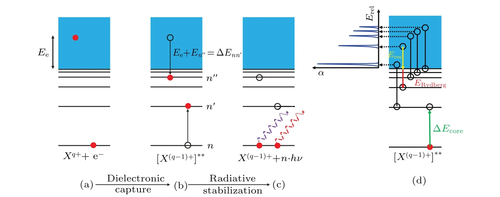
Fig.1.(a)–(c)Schematic diagram of the DR process.Step(a)→(b)represents the dielectronic capture: a free electron is resonantly captured into a Rydberg state with simultaneous excitation of a bound electron,and a doubly excited intermediate state is formed.Step(b)→(c)depicts the subsequent radiative stabilization: the intermediate state stabilizes via photon emission.(d)The DR resonant condition and the relationship between the measured DR spectrum and the electronic structure of the intermediate-state ions.In the DR process,the core excitation energy∆Ecore equals the sum of the Rydberg electron’s binding energy ERydberg and the DR resonance energy Eres.
The developments of crossed-beams and merged-beams techniques have promoted the experimental determination of DR rate coefficients.[13–15]Heavy-ion storage rings equipped with electron coolers are capable of providing a cold electron beam and a high-quality ion beam, which facilitate the precision DR spectroscopy investigation under the merged-beams arrangement.In particular,storage ring DR experiments have been recognized as a unique method to obtain low-lying DR rate coefficients.In general, the cold electron beam from the electron cooler also serves as the electron target in addition to the role of the coolant.In recent decades,several storage rings,including the TSR at MPIK in Heidelberg,[16]ESR at GSI in Darmstadt,[17]and CRYRING at MSL in Stockholm[18]have been dedicated to DR measurements.Rate coefficients for various ranges of HCIs have been determined by employing the merged-beam technique (see Refs.[1,16,19] and references therein).More recently,the main cooler storage ring(CSRm)and the experimental cooler storage ring(CSRe)at the Heavy Ion Research Facility in Lanzhou (HIRFL) started contributing DR rate coefficients for HCIs.Recombination experiments with36Ar15+,40Ar12+,13+,14+,15+,40Ca14+,16+,17+,56Fe17+,58Ni19+, and76Kr25+ions[20–29]have been accomplished at the CSRm in the past few years, and the first calibration experiment with Na-like Kr25+ions has been successfully performed at the CSRe.[30]
In this paper, the recent progress on DR experiments at the HIRFL-CSRm and CSRe is overviewed.In Section 2,the DR experimental method and basic data analysis are introduced.Here,we select the Na-like Kr25+ions as an example to illustrate the experimental techniques at the CSRm and CSRe,respectively.In Section 3,the theoretical calculation of the DR cross section by using the flexible atomic code(FAC)and the conversion to the rate coefficients are outlined.The experimental results, including the DR rate coefficients and corresponding plasma recombination rate coefficients(PRRC)for the Na-like Kr25+ions,are presented in Section 4.In Section 5,a compilation of the PRRCs for different HCIs derived from the measurements at the HIRFL-CSR is provided.Finally,a conclusion and perspective are presented in Section 6.
2.Experimental method and data analysis
The cooler storage rings at the Heavy-ion Research Facility in Lanzhou(HIRFL-CSR)were installed in 2007 at the Institute of Modern Physics,Chinese Academy of Sciences.The overall layout of the HIRFL-CSR is shown in Fig.2,including the electron cyclotron resonance(ECR)ion source,the sectorfocused cyclotron(SFC),the separated sector cyclotron(SSC),the main cooler storage ring(CSRm),the radioactive beamline RIBLL-2, and the experimental storage ring (CSRe).Based on the electron cooling devices at the CSRm and the CSRe,low-energy(Ud≤1.5 kV)and high-energy(Ud≤15 kV)DR experimental platforms for HCIs have been built.Here,Udis the output voltage of the electron energy fast detuning system.
Since the first calibration DR experiment with Lilike Ar15+ions at the CSRm in 2015,[20]DR rate coefficients of a series of HCIs, including40Ar12+,13+,14+,[21–23]40Ca14+,16+,17+,[24–26]58Ni19+,[28]112Sn35+,[31]and78Kr25+[29]ions, have been successfully obtained at the CSRm.These works have accumulated extensive experience and technical reserves, which also support the extension of DR experiments to the CSRe.At present, all the installation and commissioning have been completed and enabled the DR measurements.In particular, the combination of “CSRm +RIBLL2 + CSRe” provides an opportunity to perform DR experiments with heavy stable HCIs and even radioactive ion beams(RIBs).
Here,the DR measurements of Kr25+ion were selected as examples to illustrate the experimental method at the storage ring CSRm and CSRe.The parameters of the DR experimental setups at the HIRFL-CSR are listed in Table 1.
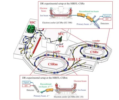
Fig.2.The schematic view of the HIRFL-CSR facility combined with the DR experimental setup at the CSRm and the CSRe.The moveable particle detectors are installed downstream of the electron cooler.The recombined ions formed in the merged region are separated from the primary ion beam by the dipole magnets and counted by the particle detectors.
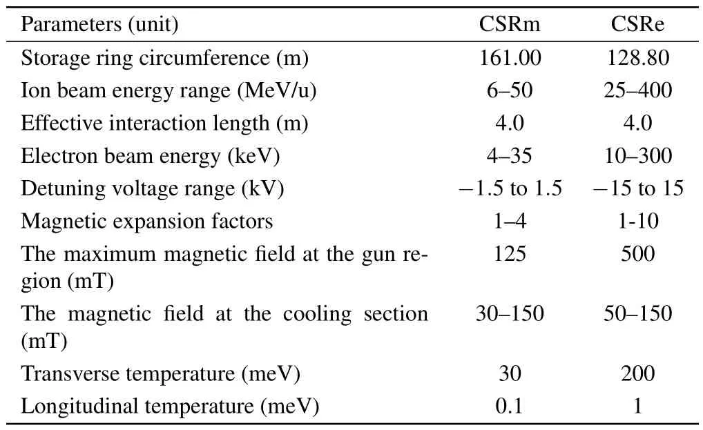
Table 1.The parameters of the DR experimental setups at the CSRm and CSRe.
For the DR experiment of Na-like Kr25+at the CSRm,the primary ion beam was produced by the electron cyclotron resonance (ECR) ion source and accelerated to an energy of 4.98 MeV/u in the SFC.During the experiment, the storage ring was operated in DC mode, i.e., the accelerated ion beam was injected into the CSRm to accumulate a maximum beam current of∼200µA, corresponding to 2.60×10⁸ions stored in the ring,and the measurement was carried out within the beam decay time.Before data recording, the stored ion beam was cooled for about several seconds by merging with the velocity matched(βion=βe)electron beam over an effective interaction length ofL=4.0 m, achieving a longitudinal momentum spread of about ∆p/p ≈2.0×10⁻⁴.The electron beam emitted from the cathode of the cooler was adiabatically expanded from the magnetic field of 125 mT at the gun section to 39mT at the guiding section, with which the perpendicular electron beam temperature was reduced tokBT⊥≈30 meV.[20]The longitudinal electron beam temperature ofkBT‖ ≈0.8 meV was achieved by accelerating the beam energy to the cooling point.[20]The electron beam at the straight section was confined to a diameter of∼52 mm with a typical spatial density of 9.62×106cm−3.The relative collision energy between the electron and ion beams is zero at the velocity-matched cooling condition.Nonzero collision energies in the center of mass (c.m.) frame were realized by loading offset voltages to the cathode HV to vary the electron beam energy according to a preset timing sequence.As shown in Fig.3,the offset energies quickly switched between the positive and negative detuning for 10 ms, and long cooling periods of 190 ms were applied after every detuning.In this approach, the ion beam quality can be maintained during the measurement.The experiment covered the detuning voltages from 0 V to 1000 V,with an equidistant step of 1 V in the laboratory frame.The measurement for each detuning step can be normally accomplished within a single injection cycle.Downstream of the electron cooler,the formed recombined ions were separated from the primary ion beam in the bending magnet and detected by the particle detector (YAP:Ce)with nearly 100%efficiency.[32]
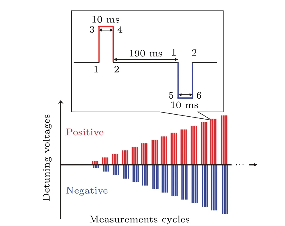
Fig.3.Typical timing sequence for the DR experiment of Na-like Kr25+ions at the CSRm and CSRe.The inset shows an enlarged view of a single measurement cycle.
For the DR experiment of Na-like Kr25+at the CSRe,the experimental method was similar to that at the CSRm.The ion beams of Kr25+were accelerated again in the CSRm and reached an energy of 80 MeV/u.The accelerated ion beam was transferred into the CSRe before the measurement cycle and cooled by the velocity-matched electron beam from the 300 kV electron cooler EC-300.The accumulated beam current reached an intensity of 450 µA, corresponding to 1.23×10⁸ions stored in the CSRe.The precooling of the Kr25+ion beam at the CSRe required 10 s since the beam energy was much higher than that at the CSRm.After electron cooling,the momentum spread of the Na-like Kr25+ion beam was reduced to ∆p/p ≈1.75×10⁻⁴.In the merging section,the electron beam was confined to a diameter of∼54 mm with a typical spatial density of 7.25×106cm−3.The same detuning strategy as the CSRm was adopted, while the upper limit of the detuning voltage at the CSRe can be boosted to±15 kV.In the present experiment, the detuning energy range is up to 5000 V, which corresponds to a collision energy of∼150 eV between electron and ion beams in the c.m.frame.During the measurement,the DC transformer(DCCT)and Schottky spectral analysis system were used to monitor the ion beam current and momentum spread (∆p/p) in realtime.The horizontal and vertical ion beam profiles were observed by residual gas ionization profile monitors.Electron and ion beam position monitors (BPMs) were applied to observe the relative position between the electron and ion beams in the merged region, thereby keeping the electron and ion beams parallel to each other and along the central axis of the cooler.To detect the recombined ions, a plastic scintillation detector(PSD) and a position-sensitive multiwire proportional chamber(MWPC)were developed and installed downstream of the electron cooler at the CSRe.[30]The photographs of the detector pocket, PSD, and MWPC are presented in Fig.4.The position-sensitive MWPC detector enables real-time monitoring of the recombined ion beam profile and spatial distribution.Note that the recombined ion beam profiles are generally identical to the primary recombining ion beam profiles.Therefore, the primary ion beam profile was monitored by the position signals, with which the accelerator staff had optimized the beam diameter of Kr25+ions from about 50 mm to about 4 mm.Figures 5(a) and 5(b) present the accumulated beam profile for the injections and the cooled beam measured by the MWPC detector.Since the ion beams are electron-cooled,the recombined ions were well confined in the active area of the MWPC detector, which ensures a complete collection of all the recombined ions in the DR experiments.
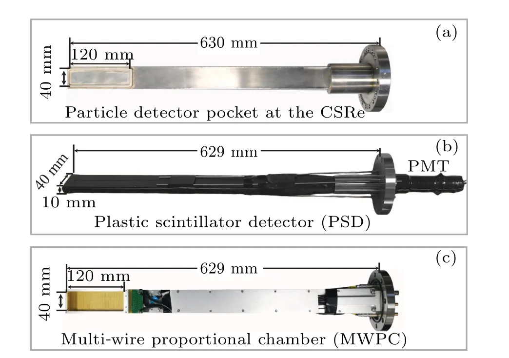
Fig.4.(a) The movable rectangular tube-like particle detector pocket at the CSRe.(b) and (c) Photographs of the assembled PSD and the MWPC at the CSRe.For more details,see Ref.[30].
The original data recorded in the experiment were detuning voltages and recombined ion counts,which need to be transformed into collision energies and rate coefficients.The relative collision energy between the electron and ion beams can be calculated by
wheremeandmiare the rest mass of the electron and ion,respectively.cis the speed of light in the vacuum.γeandγiare the Lorentz factors of the electron and ion beams,respectively.ve=βecandvion=βicare the velocities of the electron and ion beams,respectively.θdenotes the angle between the electron and ion beams.Note that the space charge effect should be taken into account,while the drag force effect is negligible in the calculation.
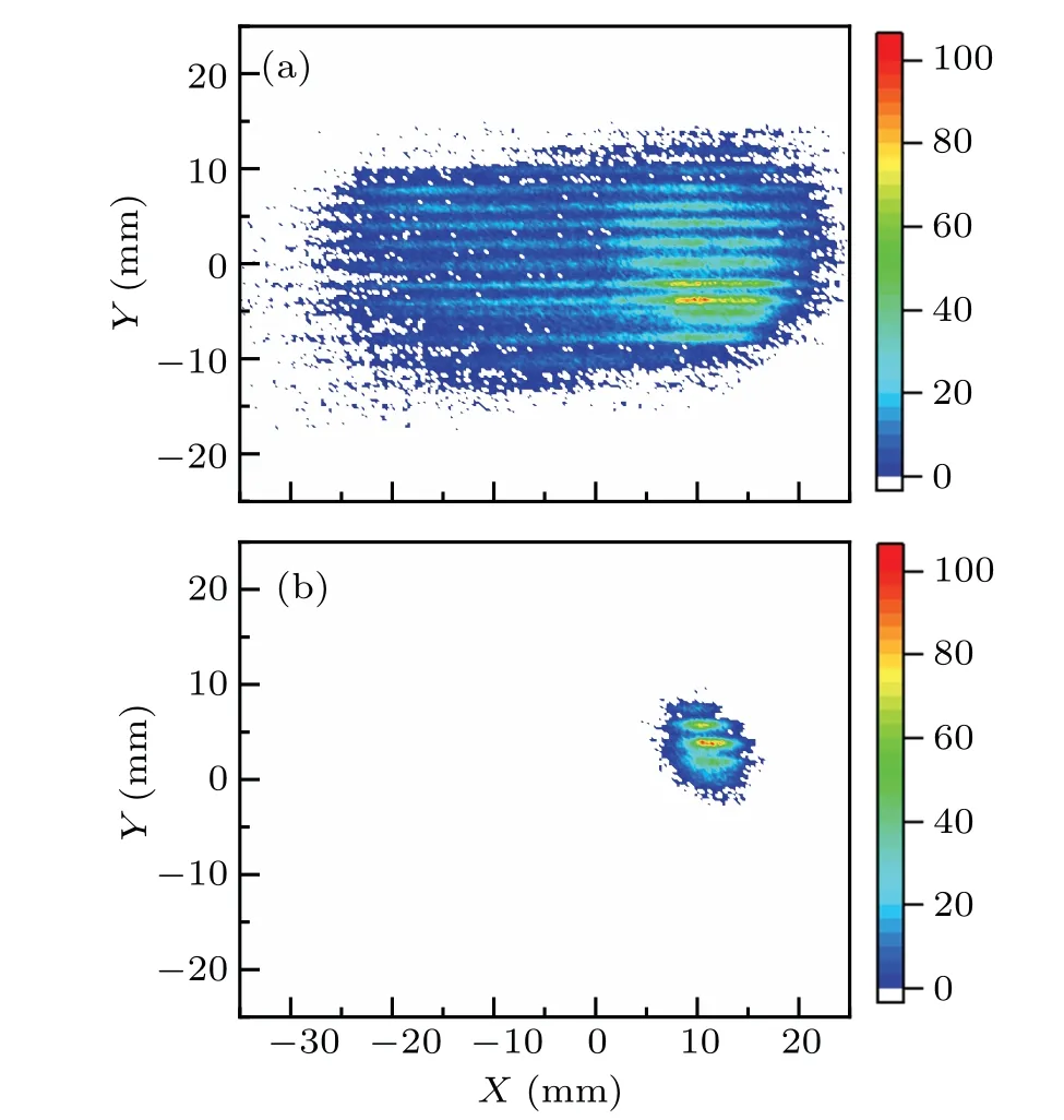
Fig.5.The beam profile and spatial distribution of the recombined ions measured in realtime by the MWPC detector at the end of beam injection and after electron cooling for 10 s,respectively.
The merged-beam DR rate coefficients in a storage ring experiment at a collision energyErelcan be deduced from the measured counting rateR(Erel)of recombined ions via
whereNiis the number of stored ions.neis the spatial density of the electron beam.Lis the effective interaction length,andCis the circumference of the storage ring.Note that the recombined ions via resonant excitation, radiative decay, or charge exchange with residual gases cannot be resolved by counting the rates, and the deduced rate coefficients consist of the resonant DR, continuum RR, and a linear background.Usually,the RR rates and residual background can be simulated by the following empirical formula:[33]
whereαi(i=0–4)are fitting parameters.The measured rate coefficients, where no DR resonances were encountered, can be used to determine the parameters by least-squares fitting.The empirical formula usually works well when there are no low-lying DR resonances below 1 eV.Otherwise, the lowenergy RR rate coefficients would be difficult to simulate since the tails of DR resonance features complicate the fitting process.In this case, the RR rate coefficients can be calculated with a modified semiclassical Bethe & Salpeter formula for hydrogenic ions.[34]The calculated RR rate coefficients and a linear function are used as substitutes for deducing the pure DR rate coefficients.
3.DR cross section calculation and the conversion to the rate coefficients
To comprehensively understand the measured DR rate coefficients at the CSRm and CSRe,the FAC is used to generate the DR cross-section.[23–25,28,29]The theoretical methods of FAC are described in detail in the references of Gu.[4,35]Here,we just give a very brief introduction to the theoretical treatment.
In the FAC calculation, atomic energy levels, autoionization (AI), and radiative decay rates were calculated with a relativistic atomic-structure program.The DR resonance strengths were calculated under the isolated resonance approximation (IRA) with the distorted-wave method based on the Dirac equation.In the calculations,the DR process was treated as two independent steps.The first step is termed dielectronic capture(DC),which can be viewed as the time inverse of the AI process.In the second step,the doubly excited intermediate states can either autoionize or decay radiatively,thereby completing the DR process.Accordingly, the DR strength via a specific doubly excited state is the product of the DC strength and the branching ratio of radiative stabilization.DC strength can be obtained from the AI rates through the principle of detailed balance via
wheregiandgfare the statistical weights of the autoionizing state formed by DC and the target state before DC, respectively.Erelis the electron-ion collision energy, andAais the AI rate.A zero-density approximation radiative branching ratio[10]can be expressed as
whereAdenotes the radiative decay rate from stateitohandAdenotes the autoionization rate.handmrepresent the levels below the ionization threshold and those after ionization,respectively.[4,36]
To compare with the experimentally derived electron–ion recombination rate coefficients,the calculated electron–ion recombination cross sections should be transformed into the rate coefficients according to the following formula:
wheref(v,v0) is the distribution function of the relative electron–ion velocity at the c.m.frame.v0is the relative electron–ion velocity at the collision energyErel.The velocity distribution in a storage ring DR experiment is almost identical to the electron velocity distribution(sinceme≪mi),which is characterized as
The distribution is a“flattened”Maxwellian since the longitudinal temperaturekBT‖is much lower than the transverse temperaturekBT⊥.The electron temperatures in an experiment can be determined by fitting the measured DR spectra.Usually, DR cross sections can be regarded as Dirac-δfunctions since their natural widths are much narrower than the experimental energy resolutions.The measured rate coefficients for an isolated DR resonance can be analytically expressed by entering Eq.(7)and theδ-type cross-section into Eq.(6)
whereξ=(1−T‖/T⊥)1/2.vdis the relative electron–ion velocity at the resonance energyEd.ˆσdcorresponds to the integrated DR cross sections.In this manner, the full width at half maximum(FWHM)of the measured DR resonance at the collision energyErelis
For the resonances with natural widths comparable to the energy resolutions, theδ-type cross sections in the convolution should be replaced by the following profile:
whereΓdis the natural width of the DR resonance.
In addition, the recombined doubly excited ions will pass through several magnetic fields before hitting the particle detector.The motional electric fields could ionize the recombined ions with a principal quantum number higher thanncutoff[37]
whereqis the primary charge state.viandBare the ion beam velocity and maximum magnetic field strengths the ions will experience.The calculations truncated atncutoffcan compare with the experimental measurements directly.The simplified picture usually works well for the field-ionization effect,but it fails in some cases.[38]A detailed model taking into account radiative lifetimes of higher Rydberg states and the flight time for the travel from the cooler to the bending magnets has been described in Ref.[38].
4.Results and discussion
4.1.DR rate coefficients for Na-like Kr25+ions
The obtained DR rate coefficients of Kr25+at the CSRm and CSRe covered the collision energy ranges of 0–70 eV,including the significant DR channels
Here,nis the principal quantum number of the captured electron.hνdenotes the decay photons.The DR resonance positions can be estimated by the hydrogenic Rydberg formula
with the Rydberg constantRy= 13.60569 eV and primary charge stateq=25.Eexcis the excitation energy.The formula works well for resonances with free electrons captured into high-nRydberg states,whereas the fine structures would complicate the cases for resonances into low-nstates.In addition to the resonances associated with the 3s→3p and 3d(∆n=0)excitations,DR channels via the 3s→4l(∆n=1)excitations are also involved in the present energy range.The backgroundsubtracted DR rate coefficients for the Na-like Kr25+ions at the CSRm and CSRe were obtained according to Eqs.(1)–(3)and are presented in Fig.6 with black dotted and blue solid curves, respectively.The resonant positions in the DR spectrum measured at the CSRe agree well with the measurement at the CSRm,while the energy resolution at the CSRe is lower than that at the CSRm.

Fig.6.Comparison between the measured DR rate coefficients of Nalike Kr25+ measured at the CSRm and CSRe in the energy range of 0–70 eV.The black dotted and blue solid curves indicate the measured DR rate coefficients at the CSRm and CSRe,respectively.
DR rate coefficients for Na-like Kr25+ions have been reported, and detailed comparisons with the FAC and AUTOSTRUCTURE calculations were made in Ref.[29].The main findings are briefly outlined below.To make a detailed comparison of the measured and theoretically calculated spectra, the longitudinal and transverse electron beam temperatures must be first determined by fitting the measured spectra with Eq.(9).As shown in Fig.7, the longitudinal and transverse electron temperatures at the CSRm are determined to bekBT‖=0.32 meV andkBT⊥=12.50 meV by fitting the DR resonances below 6.5 eV.In the same method,the longitudinal and transverse electron temperatures at the CSRe are determined to bekBT‖=1.25 meV andkBT⊥=75.80 meV.Based on the obtained electron beam temperature distribution, the theoretically calculated electron–ion recombination cross sections can be transformed into recombination rate coefficients according to Eq.(8).
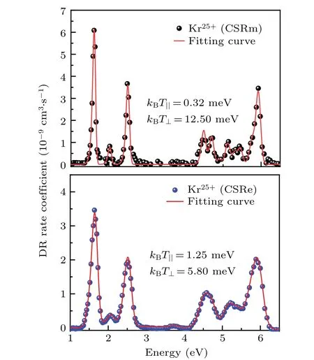
Fig.7.Fitting of the DR resonances measured at the CSRm (upper panel) and CSRe (lower panel) below 6.5 eV with Eq.(9).The black and blue dotted curves are the measured DR rate coefficients at the CSRm and CSRe,respectively.
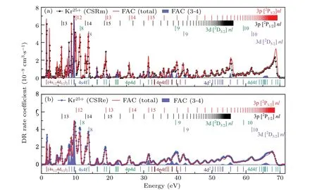
Fig.8.(a)Comparison between the DR rate coefficients of Na-like Kr25+measured at the CSRm with the theoretical calculations by FAC in the energy range of 0–70 eV.The Rydberg series of 3p[2P1/2]nl(n ≥13)and 3p[2P3/2]nl(n ≥12)dominate the DR resonance structure in the measured energy range,and the resonant positions for these two series are indicated with black and red vertical bars,respectively.The resonant positions for 3d[2D3/2,5/2]nl (n=8–10)are also indicated with vertical bars in the colors green and purple,respectively.The shadow areas in blue indicate the contribution of DR resonances associated with 3s →4l(∆n=1)excitations,and the corresponding resonant positions are also indicated with vertical bars in different colors below the curves.(b)The same as the upper panel,but for the DR rate coefficients measured at the CSRe in the energy range of 0–70 eV.

4.2.Plasma recombination rate coefficients
Plasma recombination rate coefficients(PRRC)for HCIs in different charge states are the fundamental data needed in the plasma modeling codes.[39]In contrast to the very narrow velocity distribution for the electrons in a storage ring electron–ion recombination experiment, as shown in Eq.(8), the electrons in astrophysical and fusion plasmas characterize a much broader isotropic Maxwellian velocity spread.Temperature-dependent plasma recombination rate coefficients can be obtained through Eq.(7) by entering the DR cross sections and Maxwell–Boltzmann distribution.Note that the electron temperatures in the storage ring DR experiments are usually much lower than those in the plasma, and the measured rate coefficientsα(E) are approximated equal toσ(E)·v(E).Therefore, the convolution can be simplified as
wheref(E,Te)denotes the electron energy distribution function at the plasma temperatureTe
The approximationα(E)≈σ(E)·v(E) works well for the DR resonances atEres≫kBT⊥.However, the low-lying resonances are broadened by the experimental resolution and Eq.(14) will underestimate the PRRCs at low temperatures.One should fit the experimental spectra at low energies and use the fittedσ(E)for accurate PRRCs.
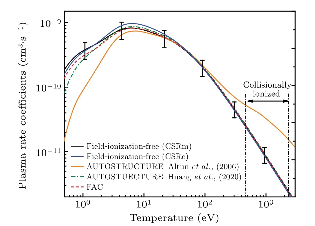
Fig.9.Comparison of the experimentally derived PRRC with the theoretically calculated results.The black and blue solid curves indicate the PRRC derived from the measurements at the CSRm and CSRe.The error bars denote the±30%experimental uncertainty of the absolute rate coefficient measured at the CSRm.The orange solid and green dashed curves are the AUTOSTRUCTURE calculated PRRC from Altun et al.(2006)[40] and Huang et al.(2020),[29]respectively.The red dashed curve denotes the FAC calculation.The approximate temperature ranges where Kr25+ is expected to form in collisionally ionized plasmas are indicated by vertical dashed bars and associated arrows.[41,42]
To give an intuitive understanding,we converted the measured DR rate coefficients and theoretically calculated DR cross sections for Na-like Kr25+ions to the PRRC according to Eq.(14), and the results are presented in Fig.9.The black and blue solid curves denote the experimentally derived PRRC at the CSRm and CSRe in which the principal quantum numbernhas been extrapolated to a very high value to obtain the field-ionization-free plasmas rates.The error bars denote the±30% experimental uncertainty of the CSRm measured absolute recombination rate coefficient.Some obvious differences of experimentally derived PRRC at the CSRm and CSRe around 10 eV are estimated to be about 10%–15%, which is still within the experimental uncertainty.These discrepancies are mainly contributed by the absolute energy scale in the DR measurements at the CSRm and CSRe.[11]The theoretically calculated results by the FAC and AUTOSTRUCTURE codes are indicated with the red dashed and green dash-dotted curves,respectively.In addition,the previously recommended PRRC data of Kr25+by Altunet al.(2006)are also presented in Fig.9 with the orange solid curve.[40]The present FAC and AUTOSTRUCTURE calculated PRRCs have achieved good agreement with the experimental values over the whole measured energy range within the experimental uncertainty.Altunet al.also performed the calculation with AUTOSTRUCTURE code, and the involved electronic configurations were almost the same as the calculation in this work.However,obvious differences can be found between these two calculated results, especially in the low-temperature range of 0–10 eV.The main reason is that we have included the necessary strong mixing effects between the low-lying ∆n= 0 (3→3) and∆n=1(3→4)DR resonances in the present AUTOSTRUCTURE calculation, but they were neglected in the calculation by Altunet al.(2006).[29]
To facilitate the use of our experimental data in astrophysical and fusion plasma modeling,the experimental PRRCs are parameterized with the following equation:
whereciandEiare the fitting parameters.
5.PRRC from the HIRFL-CSR
Temperature-dependent PRRCs of HCIs are the fundamental parameter for plasma models and are of essential importance for interpreting spectroscopic observations of astrophysical and fusion plasmas.The aim of storage ring DR measurements is to reduce atomic physics uncertainties in the basic theoretical methods and codes to point out the direction of their development.Therefore,revealing the underlying causes of the discrepancies between spectral observations and models cannot be attributed to errors in atomic data.Table 2 lists the fitting parameters ofciandEifor the experimentally derived field-ionization-free PRRC of the relevant HCIs investigated at the HIRFL-CSR.The fitted curves can reproduce the experimental plasma recombination rate coefficients within 1%–2%in the temperature range between 103–107K.
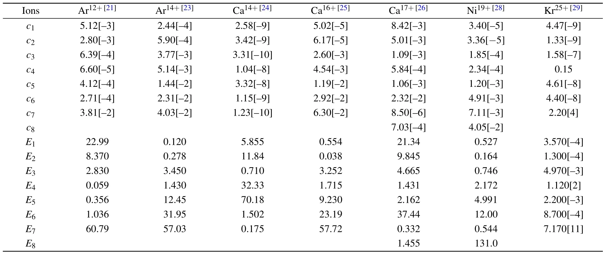
Table 2.Fitting parameters of the experimentally derived field-ionization-free PRRC for the HCIs measured at the HIRFL-CSR.The units of ci and Ei are cm3·s−1·K3/2 and eV,respectively.Numbers in the squared brackets are powers of 10.
All the datasets presented in this paper,including the fitting parameters of the experimentally derived field-ionizationfree PRRC for the Ar12+,14+,Ca14+,16+,17+,Ni19+,and Kr25+ions measured at the HIRFL-CSR are compiled in the supplementary materials in PDF format.
6.Conclusion and perspective
In conclusion, DR experiments at storage rings not only supplement the atomic database with reliable rate coefficients but also serve as benchmarks for testing and developing theoretical codes.The HIRFL-CSRm and CSRe equipped with electron coolers EC-35 and EC-300,respectively,which facilitate DR measurements under the merged-beam arrangement.Recombination rate coefficients for numbers of ions have been measured at the CSRm since the first calibration experiment in 2015.More recently,the DR experiment has also been extended to CSRe for heavier highly charged ions and higher collision energies.The measured DR rate coefficients at the CSRe agree well with the measurement at the CSRm,indicating the feasibility of the DR platform at the CSRe.Furthermore,AUTOSTRUCTURE and FAC codes were employed to calculate the DR rate coefficients and compare them with the experimental data.The measured DR resonances associated with the ∆n=0 excitations are in fair agreement with the calculations.However, the 4l4l′resonances are not well produced,which is likely to be attributed to an approximate treatment of the correlation effect and the strong mixing with adjacent configurations.The shifted 4l4l′resonances are transformed into large deviations in the plasma recombination rate coefficients at low temperatures.
DR rate coefficients measured at the CSRm constitute a set of reliable benchmarks for use in plasma models and for improving atomic codes.In the future, DR rate coefficients for astrophysical-relevant light ions and iron-peak ions could be measured at the CSRm.Precision DR spectroscopies and rate coefficients for heavy tungsten ions could be approached at the CSRe.Abundant DR experiments at the CSRm and CSRe have laid a solid foundation and paved the way for future electron–ion collision studies at the High Intensity heavy-ion Accelerator Facility (HIAF).[43]HIAF-SRing will be equipped with an electron cooler and a separated electron target,which will facilitate precision spectroscopic studies and measurements at much higher collision energies.
Data availability statement
The data that support the findings of this study are openly available in Science Data Bank at https://doi.org/10.57760/sciencedb.j00113.00092.
Acknowledgments
This work was partly supported by the National Natural Science Foundation of China (Grant Nos.U1932207,11904371, and 12104437) and the Strategic Priority Research Program of Chinese Academy of Sciences (Grant No.XDB34020000).We thank S.Schippers for fruitful discussions on the data analysis.W.Q.Wen acknowledges the support of the Youth Innovation Promotion Association CAS.The authors are deeply grateful to the staff of the Accelerator Department for the smooth running of the CSR accelerator complex.
猜你喜欢
消防界(2022年1期)2022-04-17
方圆(2022年4期)2022-04-07
美与时代·美术学刊(2022年1期)2022-03-05
上海故事(2021年12期)2021-01-20
南风(2020年7期)2020-08-07
快乐作文(1.2年级)(2019年10期)2019-09-10
时代人物(2017年6期)2018-05-02
家人(2018年1期)2018-01-16
中国新闻周刊(2017年43期)2017-12-04
艺术评论(2016年5期)2016-05-14

- Chinese Physics B的其它文章
- Interaction solutions and localized waves to the(2+1)-dimensional Hirota–Satsuma–Ito equation with variable coefficient
- Soliton propagation for a coupled Schr¨odinger equation describing Rossby waves
- Angle robust transmitted plasmonic colors with different surroundings utilizing localized surface plasmon resonance
- Rapid stabilization of stochastic quantum systems in a unified framework
- An improved ISR-WV rumor propagation model based on multichannels with time delay and pulse vaccination
- Quantum homomorphic broadcast multi-signature based on homomorphic aggregation