
An adaptive control strategy for microgrid secondary frequency based on parameter identification
2023-10-25 07:31YongShiYinChengBaoXieJianhuiSu
Global Energy Interconnection 2023年5期
Yong Shi,Yin Cheng,Bao Xie,Jianhui Su
1.Photovoltaic System Engineering Research Center of the Ministry of Education,Hefei University of Technology,Hefei 230009,P.R.China
2.State Grid Wuhu Power Supply Company,Wuhu 241000,P.R.China
Abstract: Complex microgrid structures and time-varying conditions,among other factors,cause problems in the mechanical modeling of microgrids,making model-based controller optimization difficult.Therefore,this study proposed a secondary frequency adaptive control strategy based on parameter identification,which uses an online parameter identification method to identify the parameters in the microgrid in real-time.The identified parameters are then used in the secondary frequency adaptive controller to optimize the real-time controller performance.The proposed method realizes adaptive optimization of the controller in the microgrid operation state and is applied to a microgrid with unknown parameters to adjust the controller parameters.Finally,a simulation experiment was conducted to verify the model accuracy and the frequency regulation effect of the proposed adaptive control strategy.
Keywords: Adaptive control; Genetic algorithm; Microgrid; Online identification
0 Introduction
A microgrid can effectively solve the large number of distributed power sources connected to the main grid under the “dual carbon” goal [1].Commonly used networking structures have master-slave and peer-to-peer configurations[2].The two main types of secondary frequency control for microgrids are centralized and distributed [3,4].A proportional-integral controller is commonly used as a frequency regulation controller because of its simple structure and mature parameter rectification theory [5].The proportionality and integration coefficients of PI control depend on the controlled object model,and the controller parameters are determined by offline modeling analysis or engineering experience [6,7].
In secondary frequency control,the MGCC (Microgrid central controller) takes the frequency deviations as input variables to the controller,calculates the total allocated power command,and distributes it to the secondary frequency control unit [8,9].Reference [10] proposed a secondary frequency-control strategy for multiple VSGs operating in parallel,and the controller parameters were set using typical system rectification.However,the PI controller parameters in the above studies cannot be adaptively optimized,and the frequency regulation effect may be worse in microgrid systems with variable operations.Scholars have proposed several improvement measures to address this drawback.Reference [11] combined neural network control with PI control to optimize the controller parameters.Previous studies [12,13] used fuzzy control theory to adjust the PI parameters to improve the response speed of the system.A robust adaptive PI controller was proposed in [14],which can effectively eliminate the effects caused by perturbations and distorted parameters in the model.Other control strategies such as model-free and model-predictive controls have also been proposed.However,model-free control greatly depends on the system input and output data and requires a corresponding robust design.Predictive control can cause frequency instability in the system if the model is mismatched.Adaptive algorithms have also been applied to parameter tuning [15].Adaptive controllers have the advantages of slight overshoot and high robustness.However,the development of adaptive laws depends on the physical model of the system.Therefore,the first step in designing a controller for microgrids under timevarying conditions is to obtain a microgrid system model.
However,a microgrid is a complex system with changing structures and operating parameters.A blackbox modeling method that uses the external characteristics of the system to obtain a microgrid model can solve this problem.However,the physical implications of the model parameters are unknown and do not apply to the adaptive controller designs.The traditional mechanical modeling method can overcome this drawback; however,the model is complex and difficult to apply to microgrids with unknown parameters [16].Gray box modeling combines the advantages of both methods.For example,references[17] and [18] used least squares and genetic algorithms,respectively,to identify the damping system of a VSG based on the characteristics of VSG control,and [19] proposed a genetic particle swarm identification algorithm to identify the parameters of PV grid-connected inverters.
In response to the aforementioned problems,this study proposes an adaptive control strategy for microgrid secondary frequencies based on parameter identification.The control strategy first obtains the equivalence model of the microgrid system based on mechanism analysis and then realizes online parameter identification through a genetic algorithm.It can obtain the controller-parameter adaptive law through the control stability principle,and finally apply the identified parameters to the secondary frequency adaptive controller to realize a real-time optimal controller.The main contributions of the study are: (1) the proposed method can identify equivalent parameters where commercial power supplies are widely used in real-time and the microgrid model structure changes from moment to moment,and (2) the proposed method can achieve adaptive optimization of controller parameters and is suitable for frequency control in microgrids with changing operating states at all times.
1 Typical microgrid topology and microgrid control strategy
1.1 Introduction to the topology of microgrids
The microgrid system contains multiple converters,various loads,and a microgrid central controller (MGCC).The microgrid central controller reads the operating status of the intelligent circuit breaker and issues control commands.The structure of a typical microgrid system is shown in Fig.1.

Fig.1 Microgrid system schematic
1.2 Droop control strategy
The converter adopts droop control in the microgrid system based on the power system principle.This control strategy can parallel multiple converters without a communication interconnection line.The relationship between the active frequency and reactive voltage in the droop control is expressed as follows:
whereP0andQ0are the active and reactive reference values,U0andf0are the corresponding voltage frequency reference valuesPandQare the active and reactive output values of the inverter,kmandknare the active and reactive droop coefficients,respectively,whilefandUare the frequency and voltage amplitudes of the inverter output.
1.3 Secondary frequency regulation strategy for microgrid
With droop control,the microgrid frequency decreases when the load increases.To address this problem,secondary frequency control generally regulates the frequency.Referring to the frequency-control strategy of the power system,the secondary frequency control of the microgrid system is as follows: First,an intelligent circuit breaker installed at the point of common coupling (PCC) calculates the grid frequency and then sends the frequency to the MGCC through the communication system.The MGCC compares the reference frequency with the feedback frequency and calculates the total system power reference value using a secondary frequency controller.Finally,the MGCC distributes the reference value to the converters based on the droop coefficient.The converters regulate the droop curve according to the reference value to realize frequency control of the system.The PI regulator parameters in a traditional centralized controller are determined offline,and a microgrid system model is required for offline adjustment.Because a microgrid system has a complex structure,a simplified equivalent model is generally used for parameter analysis and design.The method is suitable for microgrids with defined structures and known converter parameters.However,the system structures change during different operations because the parameters of the equivalence model cannot be obtained accurately and cannot be used.
2 Secondary frequency adaptive control strategy for microgrid based on parameter identification
Owing to the above problems,this study proposes a secondary frequency-adaptive control strategy based on parameter identification.A control block diagram is shown in Fig.2.The GA parameter online identification module uses the total distributed power reference value of the system and the frequency signal measured at the PCC.A genetic algorithm was then used to realize the online identification of the microgrid model.Finally,the algorithm obtained a frequency-response equivalent model of the microgrid.The controller parameters were optimized based on equivalent parameter values and adaptive laws.The power commands are proportionally distributed to the power generation units in the microgrid according to established rules.

Fig.2 Microgrid secondary frequency adaptive control block diagram based on parameter identification
2.1 The toolbar and its menus
To solve the problem of modeling the frequency response,this study obtained an equivalent model of a microgrid based on mechanism analysis and an online identification algorithm.Based on the secondary frequency control strategy,a frequency control block diagram of the microgrid system was obtained,as shown in Fig.3.
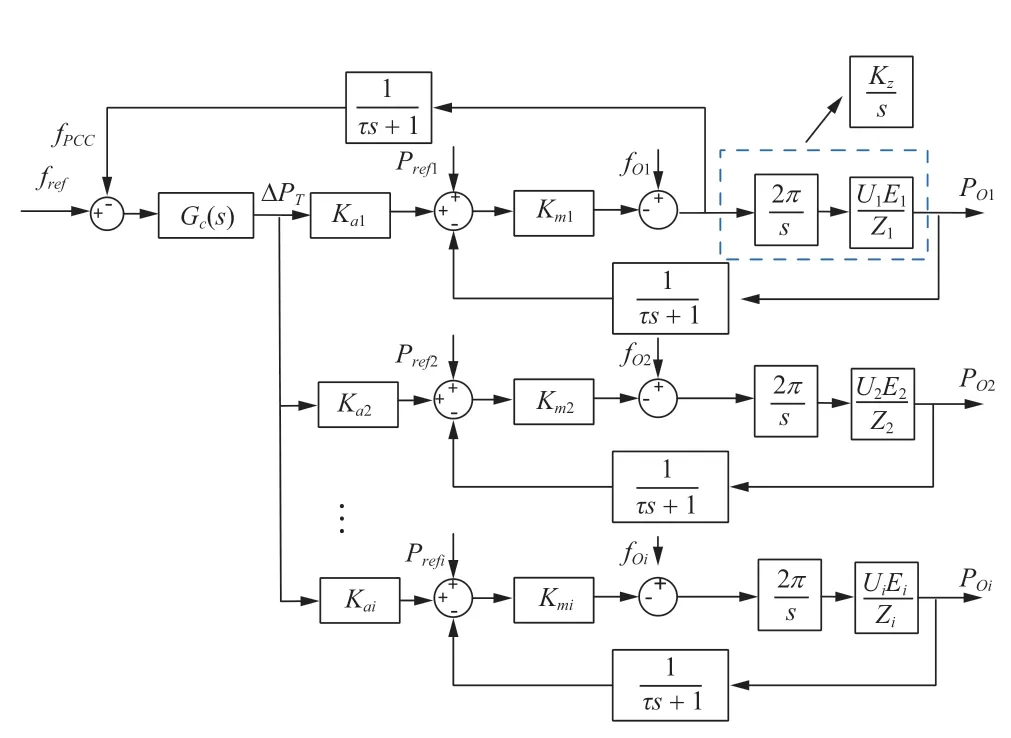
Fig.3 Microgrid system frequency response model diagram
In Fig.3,frefis the reference frequency;fpccis the frequency value measured at PCC;Gc(s) is the controller transfer function; ΔPTis the reference value of the total distributed power;Kaiis the distribution coefficient of theith converter;Kmiis the droop coefficient of theith converter;Kziis the droop output power characteristic parameter of theith converter.Prefiandfoiare the reference power and reference frequency of theith converter;POiis the output power;the communication delay time ofPOiandfpccisτ.Under the condition of satisfying power equalization,the power distribution coefficients usually have the following relations:
The frequency control block diagram of the microgrid system is equated and simplified according to [10].Multiple converters operating in parallel are equivalent to one converter.The corresponding equivalence model is shown in Fig.4.

Fig.4 Equivalence model of microgrid frequency response

Fig.5 Genetic algorithm model recognition flowchart
WhereKmindicates the equivalent droop coefficient of the multiple converters involved in frequency control,andKzindicates the equivalent droop output power characteristic coefficient.The equivalent droop coefficientKmis calculated as follows:
Referring to [10],the equivalent droop output power characteristic coefficientKzis calculated as follows:
The equivalent droop coefficient was determined by the number of converters accessible to the microgrid.Changes in loads and units change the microgrid system model,and parameter identification is the most effective way to deal with unknown and time-varying microgrid parameters.A genetic algorithm is used to identify the equivalent droop parameters.First,its equation (3) transfer function was expressed as a differential equation.
A three-point interpolation derivative formula is processed to obtain a formula in the discrete domain.
Where:nis thenth data in the discrete domain; the sampling stephis taken as 10-3; the fitness function is defined according to the properties of the transfer function of the equivalence model as
wherefpcc(n) is the actual frequency at thenth point in the discrete domain andfpcc'(n) is the calculated frequency at thenth point.
The MGCC sends the total system’s distributed power reference and frequency values at the PCC to the genetic algorithm.Population initialization randomly generates a population based on settings related to the initial population,such as the population size.Individual fitness was calculated using Equation (8) and ranked according to the fitness value.Several individuals in the population with small fitness function values were selected as parents to generate offspring populations.Individuals in the offspring population can be generated by selecting two individuals in the parent generation for coupling or by Gaussian variation.Individuals with the smallest fitness function values in the parent generation are the offspring,called elites.The elite,coupled,and mutant offspring eventually form the entire offspring population.The genetic algorithm terminates within the number of epochs set by the stopping generation if the weighted average fitness function value is less than the fitness function value deviation and continues to generate the next offspring population if is greater [20].
2.2 Adaptive controller design based on parameter identification
Adaptive controllers have a structure or parameteradjustment function.The adaptive control is governed by a nonlinear or a linear time-varying control law.In effect,the adaptive controller can automatically adjust the controller structure or parameters according to the controlled object parameters and structural changes.In Fig.3,the microgrid secondary frequency adaptive control block diagram,the controller part is taken asGc(s)=kp+ki/s,and the closed-loop transfer function of the system is as follows:
The closed-loop transfer function of the system expressed in (9) is a third-order transfer function.According to the principle of descending-order configuration,the transfer function can be analyzed and regulated to the second-order transfer function while retaining a large part of the system’s dynamic characteristics [21].In Eq.10,the system has a set of complex conjugate roots (a precondition for satisfying the optimal controller and second-order system design) and a real root.
The prerequisite for the descending-order analysis of the system transfer function isα≥5ωζn.Therefore,before the system descends,the above equation is assumed to be compliant.In a second-order system,a damping ratio of 0.707 can achieve an excellent dynamic response,which determines its poles.The system’s poles fall on a 45°dividing line between the third and fourth quadrants of the S-plane.
By combining Equation (9) with Equations (10) and (11),the characteristic equation of the transfer function can be expressed as:
Combined with the preconditions for reducing the order analysis of the system transfer function,the range ofωncan be obtained as:
As shown in the Fig.6,after the value interval ofωnis determined under the constraint of the simplified condition of the third-order system,the pole distribution region of the simplified second-order system is determined to obtain the optimal system response.

Fig.6 The position of the pole of the second-order system corresponds to the system response

Fig.7 Simplify the range of ωn values and the optimal pole distribution of the system under the constraint of simplified conditions
A simplified second-order system dynamic index constraint is used to determine the optimal range of the characteristic frequency and to deduce the equations forKpandKi.The equations represent the relationship between the overshoot and transient times with the system parameters for an optimal second-order system damping ratio of 0.707.
For different equivalent droop parameters,the PI parameter corresponding to the best response of the system is.
whereKpandKiare the parameter values of the controller,Kmis the equivalent droop coefficient value,and the controller parameter value is adjusted according to the change in the equivalent droop coefficient in different states of the system.
3 Simulation Analysis
To verify the effectiveness of the adaptive control strategy based on parameter identification,we built a model on the MATLAB/Simulink simulation platform according to the control strategy shown in Fig.3.In Case 1,the output of the identification model was compared with that of the actual model under the same operating conditions to verify the accuracy of the identification model.In Case 2,the frequency control effects of PI control and adaptive control were compared.In Case 3,the dynamic frequency-regulation capability of the controller was simulated under various types of disturbances.
3.1 Example 1: Verification of model accuracy and system stability under an adaptive control strategy based on parameter identification
The droop coefficients of the three converters in the system were set toKm1=8×10⁻⁶,Km2=5×10⁻⁶,Km3=3×10⁻⁶.The population size of the model identification algorithm was set to 100,the number of stopped generations to 50,and the deviation in the fitness function value to 10-6.The simulation results are presented in Fig.8.After 20 generations of calculations,the calculated optimal and average fitness values tended to be 0.This indicated that the difference between the actual output and the simulated output value decreased at this point and that the model parameters were identified with the valueKm=1.5×10⁻⁶.

Fig.8 Genetic algorithm optimization process identification result graph
The identification model was simulated and compared with a microgrid system under the same operating conditions to verify its accuracy.The simulated results in Fig.9 show that the identification model’s fit with the microgrid system reached 96.47%,indicating that the identification model can effectively reflect the condition of the system.

Fig.9 Frequency response waveform fit

Fig.10 Zero pole plot of the system under adaptive control
The parameters of the identification model are introduced into the controller adaptive law of Equation(14),and the optimized controller parametersKpandKiare calculated to be 9.6×10⁶and 2.9×10⁷,respectively.The parameters were introduced into the microgrid transfer function,and a characteristic root analysis was performed to obtain its zero-pole distribution.
The corresponding zero-pole diagram in the figure shows that the system is in the steady state,verifying the accuracy of the quadratic frequency-adaptive control algorithm based on parameter identification.
3.2 Example 2: Simulation analysis of conventional and adaptive secondary frequency control
The proposed control algorithm was embedded into the secondary frequency control system of the microgrid,and real-time parameter identification of the microgrid equivalent model and adaptive optimization of the controller were simulated and compared with the traditional secondary frequency control method.During the simulation,a load of 30 kW was placed on the system att=2 s to simulate a sudden increase in load during operation.The load was dropped to 0 kW att=3 s to simulate the load-shedding phenomenon during operation.The frequency response waveforms of the microgrid using the conventional PI control and the secondary frequency control proposed in this study are shown in Fig.11.

Fig.11 Adaptive control versus conventional control frequency response

Fig.12 Frequency regulation effect of microgrid with photovoltaic converter under different control strategies
The simulation results show that PI control has a greater frequency reduction and slower regulation time under the same load distribution.Even the frequency drop exceeds 0.2 Hz,which is not conducive to the stable operation of the microgrid.Therefore,an adaptive control component is essential.In the simulation results,when the system load was connected,the maximum value of the frequency reduction with adaptive control was 0.12 Hz,and the regulation time was 0.4 s; When the load was removed,the frequency fluctuation was slight,and the recovery time was short.This would benefit the stable operation of microgrids.
3.3 Example 3: Simulation analysis of dynamic secondary frequency control with photovoltaic and converter throwing
To verify the regulation performance of the proposed control strategy and its adaptability under different operating conditions,a validation test was designed for the case in which PV cells and converters access the microgrid.The operating conditions are listed in Table 1,and the parameters of the converters are identical to those described in Section 3.1.The PV converter was initially operated at an output of 1 kW.The PV converter output s assumed to reduce to 2 kW att=4 s when the solar intensity diminished.

Table 1 Experimental data
Att=1.5 s,the energy storage converter DG2is disconnected,and the structure of the microgrid changes.Att=1.7 s,the algorithm optimizes the controller parameters by using the identified microgrid equivalence model.Att=2 s and 3 s,the 30 kW load is accessed and removed from the microgrid,respectively,with a frequency regulation of about 0.16 Hz,and the microgrid frequency is regulated to the rated frequency; att=4 s,DG3is access to the operation,and the structure of the microgrid is changed.Att=4.2 s,the algorithm optimizes the controller parameters using the identified microgrid equivalence model and regulates the microgrid frequency to 50 Hz after 0.1 s; att=5 s,the PV converter output fluctuates,and the adaptive control can quickly and steadily regulate the system frequency to the rated value.t=6 s and 7 s,with the microgrid access in and removing 40 kW load,the system frequency was regulated to the rated value after secondary frequency regulation.
The secondary frequency controller parameters were kept constant using conventional PI control throughout operation.In this study,the PI controller parameters were adaptively optimized according to the microgrid system’s operating state.As the system frequency waveform shows,DG2 was removed,resulting in a change in the model parameters of the microgrid.The proposed control strategy has a significant advantage over the conventional PI controller regarding the speed of frequency regulation.
4 Conclusion
This study proposed a secondary frequency adaptive control strategy for microgrids based on online parameter identification.It solved the problems of complex microgrid modeling,time-varying conditions,and unknown internal power supply parameters.The equivalent coefficients identified by the genetic algorithm were first obtained,and then the controller parameters were adaptively optimized following typical systems analysis principles.A control stability analysis was also verified.Finally,the feasibility of the proposed adaptive control method was verified through comparative distribution simulations.
Acknowledgements
This work was supported by “the Fundamental Research Funds for the Central Universities” (Grant No.PA2022GDGP0032); National Natural Science Foundation of China (51907045).
Declaration of Competing Interest
We declare that we have no conflict of interest.
 Global Energy Interconnection2023年5期
- Global Energy Interconnection的其它文章
- Missing interpolation model for wind power data based on the improved CEEMDAN method and generative adversarial interpolation network
- A Special Issue: “Forecasting of Clean Energy and Controlling of Smart Grid for Sustainable Energy” for Global Energy Interconnection
- Wind-speed forecasting model based on DBN-Elman combined with improved PSO-HHT
- Dynamic grouping control of electric vehicles based on improved k-means algorithm for wind power fluctuations suppression
- A fuzzy control and neural network based rotor speed controller for maximum power point tracking in permanent magnet synchronous wind power generation system
- State-of-the-art review of MPPT techniques for hybrid PV-TEG systems: modeling,methodologies,and perspectives