
Classic analogue of Autler-Townes-splitting transparency using a single magneto-optical ring resonator
2023-11-02 08:10LitingWu吴利婷WenkangCao曹文康andHaolinJiang蒋昊林
Chinese Physics B 2023年10期
Liting Wu(吴利婷), Wenkang Cao(曹文康), and Haolin Jiang(蒋昊林)
1School of Information and Communication Engineering,Nanjing Institute of Technology,Nanjing 211167,China
2School of Mechanical Engineering,Guizhou University,Guiyang 550025,China
3School of Electronics and Information Engineering,Nanjing University of Information Science and Technology,Nanjing 210044,China
Keywords: magneto-optic effect,dynamic tunable,single optical ring resonator
1.Introduction
The coherent interaction of photon with atoms have attracted much attention in the recent decades such as electromagnetically induced transparency (EIT)[1-5]and Autler-Townes splitting (ATS).[6-13]ATS is the splitting of energy levels induced by the strong field-driven interactions and quantified by a transparency window in the absorption or transmission spectrum.[6]Various application explorations have also been proposed in the decades,which include millimeter wave detection,[9]light storage,[10]optical isolation,[11]and transfer of orbital angular momentum.[12]Simultaneously,the concept of ATS has been transferred to other disciplines of physics,such as nano-structured metamaterials and coupled resonator arrays.[14-26]Especially, on-chip sensors or nanoparticle detection can be achieved by utilizing ATS-like effect.[16,17,22]
Both optical ring resonator(ORR)[27-30]and whisperinggallery micro-resonator (WGMR)[15-17,31,32]are the promising platforms for classic and all-optical analogs of ATS.Similar to ATS,at least two resonances with different frequencies should be properly designed and introduced so that light interacts with them simultaneously or in some order.[14-25]For example,Penget al.provided an experimental observation of ATS-like spectra in integrated on-chip WGMR systems where the input wave interacts with the two coupled WGMRs.[20]In addition,an optical on-chip single microcavity system leading to ATS-like transparency is considered by introducing surface roughness,[14,18,19]material inhomogeneity,[26]or the presence of scatterers[16,17,22]in ORR or WGMR, and it has the obvious advantages of an easily fabrication and a compact size for better integration.
In this article,we propose a scheme in achieving an ATSlike transparency by using only one single homogeneous resonator without introducing any roughness or scatterers in an ORR.The key of this scheme is to utilize the splitting of counterclockwise and clockwise modes in a single magnetooptical(MO)ORR.[33]An ORR-waveguide configuration design is provided, which can simultaneously excite and utilize the counterclockwise and clockwise modes.When the mode degeneracy is broken, a transparency window is produced,which can be closed,open,and modified by tuning the applied magnetic fieldH0.We argue that this effect is very similar to that of ATS in quantum optics,and the external magnetic fieldH0plays the role of strong pumping field that induces a level splitting in ATS.[6,20]Numerical full-wave simulation proves the feasibility of this scheme.Practical consideration on realization and implication of this scheme,e.g.,by using available MO materials with a reduced geometric size,and the applicable frequency band of this scheme are discussed.
2.Theory and simulation
2.1.Proposal
Here we propose an induced transparency effect by using a single ORR.If we look at one ORR or equivalently a WGMR as shown in Fig.1(a),we notice that it supports both clockwise and counter-clockwise modes simultaneously.The energy fluxes of them are opposite with each other, and can be characterized by the associated optical orbital angular momentum (OAM) of±m.We are interested in the frequency regime about a single resonance,thus we would like to neglect the exact value ofmfor the sake of simplicity.We represent the clockwise mode with positive OAM by L in characterizing its left-handed nature, while the counter-clockwise with negative OAM by R.Albeit the L and R modes are degenerated in frequency if the ORR medium is isotropic, only one mode can be efficiently excited by an adjacent common waveguide bus.[28,30]For example, if a wave is incident from the upper common bus of Fig.1(a) from the left side (represented byb0),only the L mode is excited.
To excite both the L and R modes in a single ORR simultaneously, we propose a compact ORR-waveguide configuration as shown in Fig.1(a).The incident wave is coupled into two identical common buses with field amplitudesb0=a0.An ORR is placed between the two common buses.The field in the upper bus excites the L mode only,while that from the lower bus excites the R mode.The output field characterized by a complex transmission coefficienttis obtained by considering the superposition between the transmitted field componentsbtandat[see Fig.1(c)].To mimic the split energy level in ATS,we utilize the MO effect[33-39]to lift the degeneracy of the L and R modes[see Fig.1(b)].A close analogue with the strong-coupling-field-induced energy level splitting in ATS is realized.The external applied magnetic fieldH0is equivalent to the strong pump beam in ATS,and its magnitude determines the splitting of the L and R modes.[33]The resonances of L and R modes induce strong dispersion on the corresponding guided field in each common bus,and produce a transparency window in the output spectrumt.
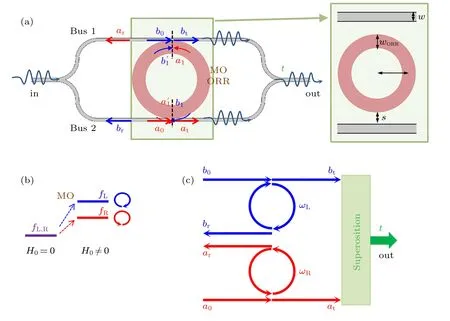
Fig.1.(a)Schematic of the proposed ORR-waveguide structure.The input bus is split into two identical common buses with an MO ORR placed in between.Inset is the geometry parameters of the structure,which is marked in green in panel(a).(b)Magneto-optic effect is introduced into the ORR to break the degeneracy of the L and R modes.(c)Wave in the upper bus excites the L mode,while that in the lower bus excites the R mode.The output wave characterized by t exhibits the superposition between the degeneracy broken L and R modes.
2.2.Formulae
The influence of MO effect over L and R modes can be briefly understood by the treatment proposed in Ref.[33].Under the excitation of an external magnetic fieldH0, without loss of generality we can assume that the permittivity tensor of the MO ORR is expressed as
where thezdirection is taken to be normal to the 2D plane shown in Fig.1(a).For the transverse magnetic (TM) polarized (i.e., magnetic filed along thezdirection) mode, the corresponding effective refractive index is given by=With increasing off-diagonal elementεkthe effective refractive indexneffreduces, so the resonances of L and R modes blue shift.The off-diagonal elementεkalso determines the broken symmetry between L and R modes, and the splitting Δfis proportional toIf it is the permeability tensorthat becomes anisotropic in MO effect,similar effect can apply to the transverse electrical(TE)polarization.
To study the ATS-like transparency in the configuration shown in Fig.1(a),we neglect details on the level splitting of L and R modes, and assume that they are represented by effective indexesnLandnR, respectively.By labeling the field components at each contact point as those shown in Fig.1(a),and assuming that the self-and cross-coupling coefficients of L and R modes to the upper (lower) common bus areγuandκu(γlandκl), respectively, we obtain a set of equations as follows:
where
dis the diameter of ORR,f=ω/2πis the frequency,γu,lare real,whileκu,lare imaginary,with
Solving the above equation set we can find that the field inside the ORR is enhanced by factors
The magnitudes ofqL,Rare maximum at the Fabry-P´erot-like resonancesfL,Rgiven byφL,R=2|m|π,i.e.,
where±mis the topological indexes of the L and R modes.
The complex transmission coefficienttdetected at the output port is given by
which,witha0=b0,can be explicitly expressed as
wherek=2π f/c,nbandsare the refractive index and the path length of the common bus, respectively.In the case ofnR=nL=nandγl=γu=γ,tbecomes
In the above consideration we have assumed that the path lengthes through the two common buses are same(sa=sb=s).If the path lengthes are unequal (sa/=sb), additional item is introduced,which can also be utilized,e.g.,for filter application.
Equation (11) depicts that the transmittance of this configuration is associated with the superposition between two Fabry-P´erot-like resonances of the L and R modes.Figure 2 shows an example on the transmission spectra and phase when the degeneracy of L and R modes is broken by the MO effect.We can see that, due to the mode splitting, the primary one resonance transmission dip splits into two separated ones about the L and R resonances.The initial smooth variation of phase from 0 to 2πis replaced by two Fano-like dispersions.We also calculate the field amplitude ratios ofqLandqRcharacterizing the enhancement of field inside the MO ORR.As is expected,the ratios have their maximum values of(1-γ2)-0.5~10 about the L and R resonances.Since the L and R modes have comparable quality-factorsQcharacterized by Eqs.(7)and(8),and the above analysis does not involve the effective refractive of index that implies the interferences between two Fano resonances.This transparency is an ATS-like one.[16,22,25]
2.3.Simulation verification
In the above analysis we have neglected the possible dispersions over the refractive indexes (n,nL, andnR) and coupling coefficients(γu,landκu,l).Radiation loss is also ignored.Here we perform a serial of full-field optical simulations by using the finite element method (FEM) to verify the above theoretical analysis.In the numerical simulations, width of the waveguide in forming the ORR and the common buses iswORR=w=0.4 mm,radius of the ORR isρ=10.2 mm.The two identical common buses are long enough to avoid the coupling between ORR and the curved waveguiding structure at the input and output sides.Refractive index of the common bus is set to be 2,and the surrounding medium is vacuum.For the sake of simplicity, we assume that the values of elements in the permittivity tensor of the MO ORR are constant, withεr=4.
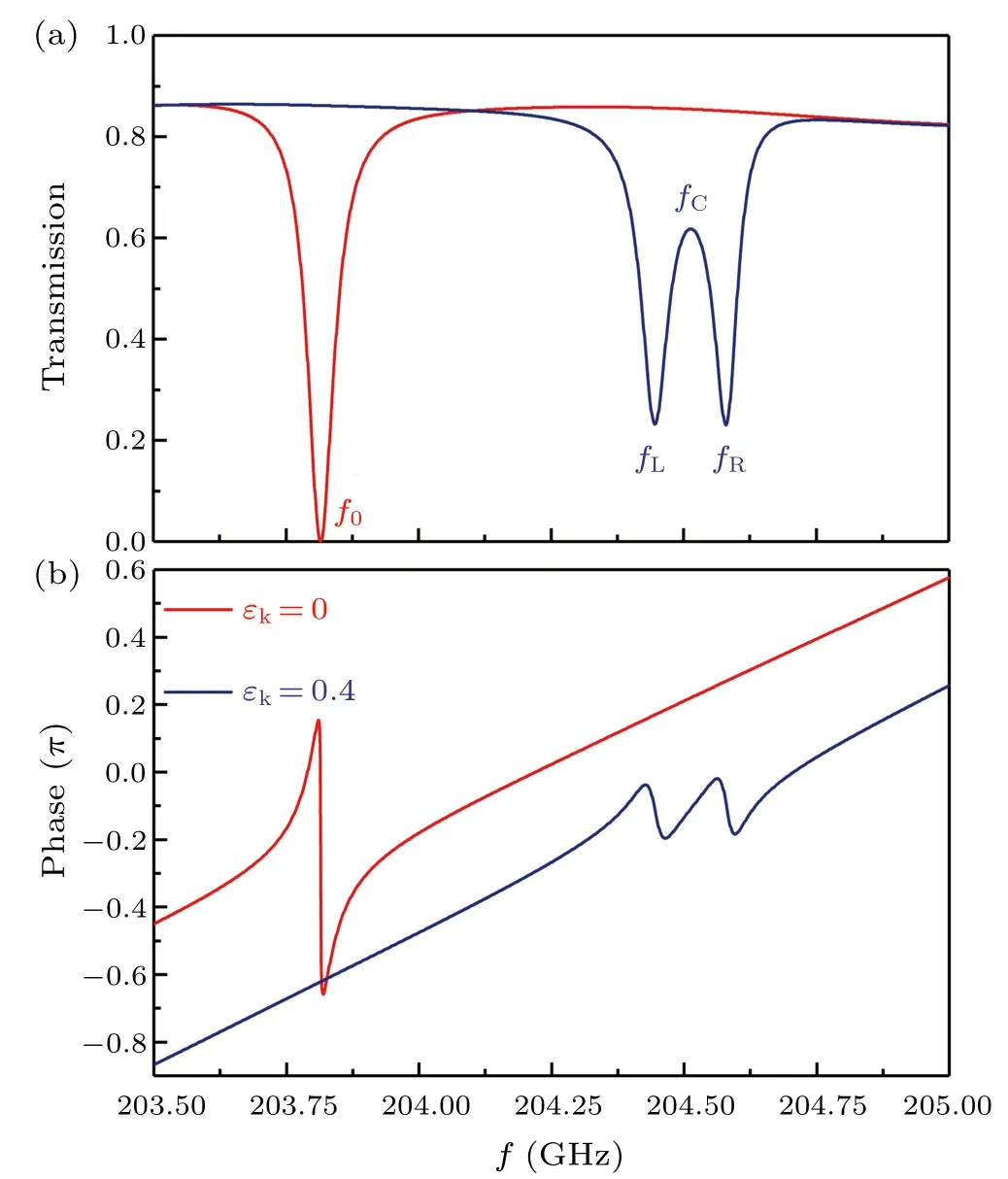
Fig.3.Simulation results of(a)transmission spectra and(b)phase for εk =0 (red line) and εk =0.4 (blue line).Geometric parameters are wORR=w=0.4 mm,ρ =10.2 mm,and s=0.6 mm.The background contribution of nbks in Eqs.(11)and(12)is taken into account.
To emphasize the superposition described by Eq.(11)and get a clear exhibition on the associated field distributions,we firstly set the gapsbetween ORR and each bus to be 0.6 mm,and assume that the off-diagonal elementεkis 0 and 0.4, respectively.The simulation results are shown in Figs.3 and 4.The maximum transmission coefficientT=|t|2does not reach 1 because the splitting and bending of the straight waveguide at the input and output ports in connection with the common buses produces a weak leakage damping on the guided modes.
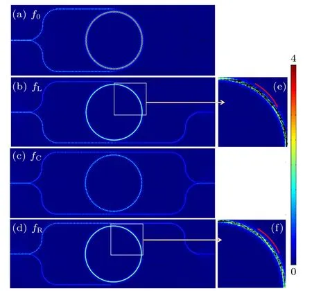
Fig.4.Distribution of field amplitude H at (a) f0 = 203.815 GHz,the transmission dip when εk =0, (b) fL =204.446 GHz, (d) fR =204.58 GHz, and (c) fc =204.513 GHz, when εk =0.4, respectively.(e) and (f) Zoomed-out images of the distribution of transverse energy flux inside the MO ORR.Geometric parameters are wORR =w=0.4 mm,ρ =10.2 mm,and s=0.6 mm.
From Figs.3 and 4 we can see that whenεk=0,where the resonances of L and R modes are degenerated(fL=fR=f0),only one transmission dip atf0=203.815 GHz can be observed.The phase oftpossesses a single Fano-type shape.At the transmission dipf0the waves from the upper common bus and the lower one superpose with each other, especially inside the ORR[see Fig.4(a)].Transverse energy flux inside the ORR is zero due to the balanced contributions of L and R modes.The field componentsbtandatare very weak.
When a nonzeroεkof 0.4 is introduced,the transmission dip shifts tofC= 204.513 GHz.This blueshift can be explained because the corresponding effective refractive index is briefly given byn2eff=(ε2r-ε2k)/εr, which becomes smaller whenεkincreases.Furthermore, due to the MO effect the transmission dip splits into two separated ones, and produces a transparency window aboutfC.Phase oftis characterized by two correspondingly Fano-like shapes.For the distribution of field intensity,at the transmission dips offLandfRshown in Figs.4(b)and 4(d),field inside the MO ORR is almost homogenous because only one of the L and R modes dominates.The dominated mode determines the observable direction of transverse energy flux,see Figs.4(e)and 4(f).Using Fig.4(b)as an example here, at this frequency the L mode is resonant enhanced inside the MO ORR.As a result, the waveb0from the upper common bus is resonantly coupled into the MO ORR via the Fabry-P´erot-like resonance of Eq.(8).This resonance substantially reduces the transmitted fieldbt,and increases the reflected wavebr.Superposition pattern betweenbranda0components can be clearly observed in the above section of the lower common bus.The fieldbtin the later section of the upper common bus is zero.For the wave incident from the lower common bus,it is weakly coupled into the MO ORR because the R mode is out of resonance.For the induced transparency windows atfCshown in Fig.4(c),because the L and R modes are all out of resonance, the waves in both common buses do not efficiently coupled into the MO ORR,rending observable transmittance at the output port.
2.4.Further feasible analysis and discussion
With an academic curiosity, the FEM simulation presented in Subsection 2.3 demonstrates the physical mechanism of the proposed ATS-like transparency.A largeεkvalue of 0.4 is considered.The geometric parameters are chosen in the way that the field is only moderated enhanced inside the MO ORR.However,in realistic situation a largeεkvalue requires a huge external applied magnetic fieldH0that may beyond the-state-of-the-art techniques.[33,35,40]Also, it is interesting to ask whether the mechanism can be realized in structure with a compact size.A feasible analysis on these practical implication issues is required.

Fig.5.Simulation results of the transmission spectra for different nonzero off-diagonal elements εk =0, 0.002, 0.005, and 0.01, respectively.Here the distance s between the common bus and the MO ORR is increased to 1.15 mm to enhance the Q factor.Other parameters are wORR =w=0.4 mm and ρ =10.2 mm.In Bi:GdIG a field H0 in the order of 0.02 T can easily render εk=0.002.
For the first problem on the large value ofεk, it can be easily avoided by increasing theQ=f/Δffactor of the transmission dips.When theQfactor is increased, i.e., the dip width Δfis substantially reduced, it becomes easier to distinguish the weaker frequency split in L and R modes associated with a smallerεkvalue.An enhancedQfactor can be obtained by simply increasing the values of self-coupling coefficientsγlandγu.Figure 5 shows the FEM simulation results when the distance between the common bus and the MO ORR is increased to 1.15 mm.We can see that the corresponding width Δfof the transmission dip becomes narrower,to~0.001 GHz that is around two orders smaller than the value of 0.07 GHz shown in Fig.3.Now we can distinguish the weak degeneracy broken modes and obtain a transparency window even atεk=0.002.If Bi-doped gadolinium iron garnet (GdBi)3Fe5O12(Bi:GdIG) commercially available is utilized as the MO medium,a fieldH0in the order of 0.02 T[40]can easily excite the required nonreciprocal anisotropy.
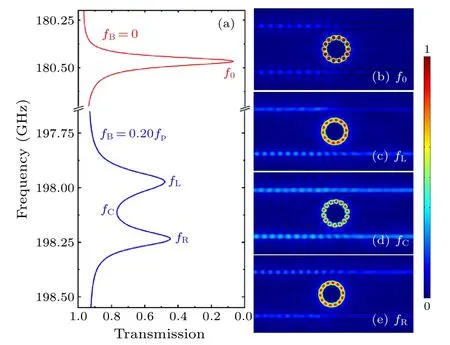
Fig.6.Simulation results of(a)transmission spectra when fB=0(red curve),and 0.20fp (blue curve),respectively.The distributions of field around the MO ORR at the transmission dips and transparency windows are plotted in(b) f0 =180.466 GHz,(c) fL =197.971 GHz, (d)fC =198.111 GHz,and(e) fR =198.231 GHz,respectively.Geometric parameters are wORR=w=0.4 mm,ρ=0.8 mm and s=0.38 mm.The topological indexes of the L and R modes are m=±7.This figure shows that the structure can be substantial reduced.
For the problem in applying this scheme to structure with a reduced geometric size, the main obstacle is the increased radiation loss and the corresponding reducedQfactor when the radius of the ORR decreases.We should utilize an MO material with a possible largeεkvalue.Semiconductors with proper doping associated with strong dispersions onεrandεkcan be utilized.Consider InSb with a doping densitynof 3.747×1013cm-3as an example,[34]the elements of permittivity tensor areεr=ε∞-f2p(f2-f2B+jf2Γ)-1,εk=fBf2pf-1(f2-f2B+jf2Γ)-1,andεz=ε∞-f2p(f2+jf2Γ)-1,respectively.Hereε∞= 15.68 is the permittivity at high frequency,fp= 464.45 GHz is the bulk plasma frequency,andΓ=0.0001 represents damping.A static magnetic fieldH0=0.05 T can renderfB=0.20fp.Figure 6 shows the FEM simulation results by using InSb in forming the MO ORR.Radius of the InSb ORR is 1 mm,and the gap between the ORR and each waveguide is 0.38 mm.All the other parameters are identical to these present before.We can see that an induced transparency can be obtained as well, and the topological index of the excited mode is reduced toC.Distributions of field at the transmission dips and transparency window are similar to those in Fig.4.
The exploration on this proposal is not limited to the above analysis.We also wander what is the applicable frequency range for this design and how to determine it.The frequency range of the ATS-like effect varies with different MO materials, which goes roughly from 5 GHz to 17 THz.[41-45]The effective frequency range for the given MO material is also worthy of study (see Appendix A).Meanwhile, it is interesting to study the influence of waveguide width in forming the MO ORR on the induced transparency window and the difference of ORR and cylinder (see Appendix B).Last but not least, can this proposal be verified by experiment and what are its applications? In fact, with the-state-of-the-art techniques researchers can fabricate ORRs for operation up to infrared and visible light already.[19,30,46,47]On-chip MO optical resonators monolithically integrated on silicon have also been demonstrated.[43,44]Particularly,Yuanet al.experimentally demonstrate an isolator with ultrahigh isolation ratios by coupling the MO material InSb with a ring resonator.[43]It further validates the experimental feasibility of our proposal.Since the values ofεrandεkcan be tuned by manipulating the external magnetic fieldH0[see Figs.3 and 5], the proposed nonreciprocal induced transparency is dynamically tunable,to open,close,and change the transparency window for various applications that have been widely discussed in slowlight society.[48]
3.Conclusion
In summary,we have proved the feasibility in realizing an ATS-like transparency effect by using a single MO ORR.This effect is based on the mode splitting on the L and R modes in the MO ORR.Within a proposed ORR-waveguide configuration design the superposition between the two degeneracy broken modes produces a transparency window,which can be closed, open, and modified by tuning the external pump field(i.e.the applied magnetic field).We provide a theoretic analysis on the transmission,and numerically demonstrate the effect using FEM simulation.We also prove that the proposed scheme can be realized by MO materials commercially available.Such an analogue of ATS transparency and the associated slow light effect[48]can be subsequently utilized for various on-chip applications such as those in integrated optical circuits.[15,20]
Appendix A:Discussion of applicable frequency range
The above theoretical analyses and simulations show that the induced transparency window for the given OAM of±moccurs in a narrowband.For example, in Subsection 2.3, the operating frequency is around 204 GHz when|m|=61.From Eq.(9),we deduce that the two transmission dips can be tuned flexibly by changing the radius of MO ORRρor OAM of±mfor the given effective indexesnL,R, which is related toεrandεk.However, in actual MO materialsεrandεkare the functions of frequency, which limit greatly the frequency band of ATS-like effect.We take the MO material InSb withfB=0.20fpdiscussed in Subsection 2.4 for illustration in the following.
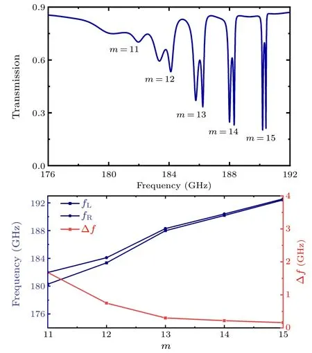
Fig.A1.(a) Simulation result of transmission spectra with different OAM of ±m when fB =0.20 fp and (b) the corresponding two transmission dips fL, fR and dip splitting Δf.Here the MO material is InSb with a doping density n=3.747×1013cm-3.Geometric parameters are wORR =w=0.4 mm, ρ =2 mm, and s=0.38 mm.This figure shows the effective bandwidth of InSb under a static magnetic field H0 of 0.05 T.
Figure A1(a) shows the FEM simulation result of transmission spectra at the frequency range from 176 GHz to 192 GHz,where the induced transparency windows with|m|=11,12,13,14,15 are excited.Here the geometry parameters arewORR=w= 0.4 mm,ρ= 2 mm, ands= 0.38 mm.The frequency band is basically consistent with the theory.Due toεr>εk>0, the operating frequency should satisfyf >173 GHz.Then the splitting decreases with increasing frequency as shown in Fig.A1(b),which is in accordance with Δf∝εk/(ε2r-ε2k).[33]For|m|>15, it becomes more difficult to distinguish the weaker frequency splitting in L and R modes.In short, the effective range offis about 176-192 GHz for InSb with the magnetic fieldH0=0.05 T, and we can modify it by tuning the applied field for practical applications.For example,the applicable frequency range is about 170-190 GHz whenfB=0.18fp,which can be easily achieved by reducingH0.Moreover,the applicable frequency range can be tuned by utilizing different MO materials.[41-45]
Appendix B: Influence of waveguide width in forming MO ORR
To better explore the influence of waveguide widthwORRin forming MO ORR,we firstly set the permittivity tensors of the MO ORR and common bus are the same as those in Section 2.3, which ensures thatnLandnRare constant anddis the only variable in Eq.(9).As shown in Fig.B1, L and R modes move to higher frequency and the frequency splitting increases with decreasingwORR.Here other parameters arew=0.4 mm,s=0.6 mm,ρ=10.2 mm,and|m|=61.It can be explained by the equivalent diameter of MO ORR.Thoughρis a constant, the electromagnetic field in MO ORR is not uniformly distributed but concentrated on the outer side.That is to say,the decreasingwORRleads to the decreasing outer radiusρout=ρ+0.5wORRand equivalent diameter of MO ORRd,in turn results in the increasingfL,Rand Δf.
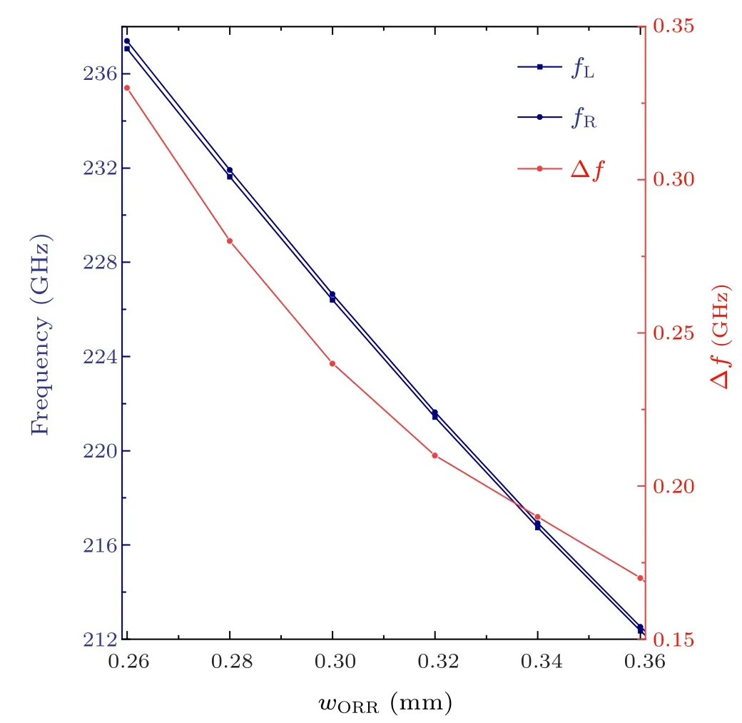
Fig.B1.The two transmission dips fL, fR and dip splitting Δf versus width of the waveguide in forming MO ORR.Here the values of elements in the permittivity tensor of the MO ORR are constant, with εr = 4 and εk = 0.4.Other geometric parameters are w = 0.4 mm,ρ =10.2 mm,and s=0.6 mm.The topological indexes of the L and R modes are m=±61.
Meanwhile,we prove the feasibility that the analogue of ATS transparency can be achieved when the MO ORR is replaced by an MO cylinder, which is just the limit case thatρout=wORR.To avoid the radiation loss whenρis a small value, we take InSb withfB= 0.20fpfor illustration.As shown in Fig.B2,fL,Rand Δfno longer change whenwORRis greater than 0.7 mm.It is just the case that the equivalent diameter does not change whenwORRis large enough.Here we setρout=ρ+0.5wORR=1 mm,w=0.4 mm, ands=0.38 mm.The FEM simulation results of field distribution infL,fC, andfRare shown in Figs.B3(b)-B3(d).Hereρout=wORR,i.e.,the MO cylinder replaces the MO ORR.It is proved again that the outer radius of MO ORRρouthas greater influence onfL,Rand Δf.

Fig.B2.The two transmission dips fL, fR and dip splitting Δf versus width of the waveguide in forming MO ORR when fB=0.20 fp.Other geometric parameters are w=0.4 mm, ρout =ρ+0.5wORR =1 mm,and s=0.38 mm.Here the MO material is InSb with a doping density n=3.747×1013 cm-13.The topological indexes of the L and R modes are m=±7.
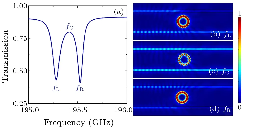
Fig.B3.Simulation results of (a) transmission spectra when fB =0.20 fp.The distributions of field around the MO cylinder at the transmission dips and transparency window are plotted in (b) fL =195.286 GHz, (c) fC =195.406 GHz, and (d) fR =195.523 GHz, respectively.Radius of the MO cylinder is 1 mm, other parameters are w=0.4 mm and s=0.38 mm.The topological indexes of the L and R modes are m=±7.
Acknowledgments
This work was supported by the National Natural Science Foundation of China (Grant No.12104227), the Scientific Research Foundation of Nanjing Institute of Technology(Grant No.YKJ202021),and the Guizhou Provincial Science and Technology Projects(Grant No.ZK[2022]general 035).
- Chinese Physics B的其它文章
- Single-qubit quantum classifier based on gradient-free optimization algorithm
- Mode dynamics of Bose-Einstein condensates in a single-well potential
- A quantum algorithm for Toeplitz matrix-vector multiplication
- Non-Gaussian approach: Withstanding loss and noise of multi-scattering underwater channel for continuous-variable quantum teleportation
- Trajectory equation of a lump before and after collision with other waves for generalized Hirota-Satsuma-Ito equation
- Detection of healthy and pathological heartbeat dynamics in ECG signals using multivariate recurrence networks with multiple scale factors