
Design of new resonant magnetic perturbation coils on the J-TEXT tokamak
2023-11-19 13:32ZhuoHUANG黄卓SongZHOU周松JinrongFAN樊金荣DaLI李达BoRAO饶波NengchaoWANG王能超YonghuaDING丁永华FeiyueMAO毛飞越MingxiangHUANG黄名响WeiTIAN田微ZhongyongCHEN陈忠勇ZhipengCHEN陈志鹏YunfengLIANG梁云峰3andtheTEXTTeam
Plasma Science and Technology 2023年11期
关键词:永华
Zhuo HUANG (黄卓) ,Song ZHOU (周松) ,Jinrong FAN (樊金荣) ,Da LI (李达) ,Bo RAO (饶波) ,Nengchao WANG (王能超) ,Yonghua DING(丁永华),Feiyue MAO (毛飞越),Mingxiang HUANG (黄名响),Wei TIAN (田微),Zhongyong CHEN (陈忠勇),Zhipeng CHEN (陈志鹏),Yunfeng LIANG (梁云峰),3and the J-TEXT Team
1 College of Computer Science,South-Central Minzu University,Wuhan 430074,People’s Republic of China
2 International Joint Research Laboratory of Magnetic Confinement Fusion and Plasma Physics,State Key Laboratory of Advanced Electromagnetic Engineering and Technology,School of Electrical and Electronic Engineering,Huazhong University of Science and Technology,Wuhan 430074,People’s Republic of China
3 Forschungszentrum Jülich GmbH,Institut für Energie-und Klimaforschung-Plasmaphysik,Partner of the Trilateral Euregio Cluster (TEC),Jülich D-52425,Germany
Abstract The resonant magnetic perturbation(RMP)system is a powerful auxiliary system on tokamaks.On the J-TEXT tokamak,a set of new in-vessel coils is designed to enhance the amplitude of the RMP.The new coils are designed to be two-turn saddle coils.These two-turn saddle coils have been optimized in terms of their structure,support,and protection components to overcome the limitations of the narrow in-vessel space,resulting in a compact coil module that can be accommodated in the vessel.To verify the feasibility of this design,an electromagnetic simulation is performed to investigate the electrical parameters and the generated field of the coils.A multi-field coupled simulation is performed to investigate the capacity of heat dissipation.As a result of these efforts,the new RMP coils have been successfully installed on the J-TEXT tokamak.It has significantly enhanced the RMP amplitude and been widely applied in experiments.
Keywords: fusion engineering,tokamak,resonant magnetic perturbation coil,multi-field coupled simulation
1.Introduction
Resonant magnetic perturbation (RMP) has shown great success in improving plasma performance in fusion devices over the past few decades [1].It has been demonstrated that RMP has profound effects on the magnetohydrodynamic(MHD) control,such as the modulation of the locked mode[2] and the suppression of the edge localized mode [3,4].RMP is a current solution for ITER [5,6] and a promising candidate for future devices to address the error field and edge localized mode [7].It has also been proven that RMP has a substantial impact on plasma transport [8,9].The RMP system has become a powerful auxiliary system and has been widely equipped on various fusion devices.
The RMP coil gets its name from its ability to generate RMP.Depending on the use and machine condition,the scale,location,and shape of the RMP coils can differ in various tokamaks.For example,four large saddle coils are installed on JET in the vacuum chamber for error field correction[10].On RFX,the coil is smaller but covers the plasma all-roundly with an 8×16 array for MHD control[11].The RMP coil on TEXTOR is helical and located at the inboard high field side[12].Despite these differences,the shared considerations in the design of the RMP coil include the RMP spectrum,the capability of carrying current,and the electromagnetic load induced by the strong poloidal and toroidal fields.However,for the in-vessel RMP coils,additional challenges must be addressed,such as the plasma strike,impurity sputtering,and cooling.The in-vessel RMP coils on the J-TEXT tokamak are called dynamic RMP (DRMP) coils [13].The DRMP coils are named for their ability to generate high-frequency rotating RMP in alternating-current (AC) conditions.They play a crucial role in the research of the J-TEXT tokamak.Abundant results in the fields of MHD instability,plasma disruption,and edge transport are obtained by utilizing the DRMP system [14].However,the amplitude of the DRMP cannot gradually meet experimental requirements with the development of research.An effective solution is to design new RMP coils with more turns.According to the previous structure of the single-turn DRMP coils,multi-turn coils cannot be fulfilled on the J-TEXT tokamak due to the limited in-vessel space.Hence,an optimized structure has to be proposed for the design of the multi-turn coils.The compact structure of the multi-turn coils makes heat dissipation more difficult than the single-turn coils.Additionally,the effects of the change in electrical parameters on the power supply and the eddy effects on the amplitude and phase of the generated field have to be taken into consideration for the new RMP coils.
To address the above problems,this work proposes a compact structure for the coils and manages to design a new set of two-turn in-vessel RMP coils on the J-TEXT tokamak.The electromagnetic simulation is employed to investigate the electrical parameters and the generated field of the newly designed RMP coils.The multi-field coupled simulation is employed to investigate the capacity of heat dissipation.The results of these simulations demonstrated the feasibility of the proposed design.The newly designed coils have been successfully installed on the J-TEXT tokamak and have been widely applied in J-TEXT experiments.In the rest of this paper,the structure design of the new coils is given in section 2.Section 3 shows the simulation of the new coils.Section 4 shows the implementation of the new coils and section 5 is the conclusion.
2.Structure design of the DRMP-2 coils
J-TEXT is a circular,limiter tokamak with a major radius of R0=105 cm and a minor radius of a=25-27 cm.The toroidal field Btof typical J-TEXT discharges is around 2.0 T and the plasma current Ipis around 200 kA [15].To distinguish the two sets of in-vessel coils on the J-TEXT tokamak,the coils to be designed are named DRMP-2 coils and the previous DRMP coils are renamed DRMP-1 coils.The distribution of in-vessel components on the J-TEXT tokamak is relatively compact.The limited space in the vacuum vessel poses significant challenges to the design of the multi-turn DRMP-2 coil.The occupied regions of the in-vessel components in port 3 are shown in figure 1.The DRMP-2 coils are expected to be placed at the top,low field side(LFS),and bottom inside the vacuum vessel,similar to the distribution of the DRMP-1 coils [13].The minimum distance from the last closed surface to the vessel wall is 61 mm.It limits the height of the protection component of the coil.At the same time,a sufficient distance between the conductor of the coil and the vessel wall has to be maintained to reduce the eddy current in the AC condition[16].There are three windows at the top,the LFS,and the bottom of the port.These windows are usually occupied by various diagnostics.The coil cannot block the view of diagnostics from these windows.As shown in figure 1,the maximum width of the coil module is 125 mm,which is similar to the width of the DRMP-1 coil module.Placing multi-turn coils at a similar width requires a more compact design of the structure.The coil,support,and protection components are optimized to achieve a more compact coil module,as described in the following sections.
2.1.Layouts of the DRMP-2 coils
Layouts of the DRMP-2 coil are designed with careful consideration of spatial limitations,as shown in figure 2.The DRMP-2 coils have been designed as two-turn coils.Figures 2(a) and (c) show the models of the top and bottom coils in various ports.The main effective areas of these two types of coils are nearly identical,with only slight differences in the coil outlet.The outlets of these two coils are designed around the high field side and the LFS to enable their adaptation to different ports with distinct occupied outlet flanges.Figure 2(b) shows the LFS coil.Compared with the top and bottom coils for which different outlet designs are necessary,one design of the outlet for the LFS coil is sufficient,as indicated by the on-site investigation.An additional feature of these two-turn coils is that their main effective areas are designed into a planar structure to reduce the height of the coil module.A twist is designed on the coil near the vertical outlet to avoid overlapping between turns while maintaining the planar structure.The coil can be wound in two turns and led out on one surface,to ensure that there is a sufficient distance between the coil and the plasma boundary.
2.2.Structure of the support part and the graphite armor
The structure of the support part and the graphite armor is shown in figure 3.To protect the coil from plasma strikes and reduce the number of high-Z impurities sputtered into the plasma,graphite armors are utilized to cover the coil.The graphite armor is coated with SiC to reduce sputtering induced by the plasma strike.The support part is made of 316 L non-magnetic stainless-steel.It consists of an upper cover and a base to support and fix the coil.There are screw holes on the top of the upper cover,which cooperate with the screw holes of the graphite armor,allowing the graphite armor to be fixed to the upper cover.This design of the graphite armor is distinct from the previous DRMP-1 coil as well as coils on several other machines,which fasten the graphite armor to the vessel wall instead of the support part.This design of the DRMP-2 coil module allows us to assemble the coil,the support parts,and the graphite armors easily outside the vacuum chamber,and then directly weld the whole coil module to the vacuum chamber.It avoids complicated assembly operations in the narrow vacuum chamber,greatly reduces the difficulty of assembly,and makes the disassembly and reassembly of the coil easier.In addition,a groove is designed in the middle of the upper cover for wiring saddle magnetic probes which are expected to be highly coupled to the RMP coil [17].
2.3.Structure of the cross-section layer
Compared with DRMP-1 coils,the cross-sectional area of the two-turn coil has to be smaller due to the limitation of the invessel space.To maintain its capacity for carrying current,the coil is designed to be more compact to ensure a sufficient cross-sectional area for carrying current.Cross-sections of the DRMP-1 coil and the DRMP-2 coil are shown in figure 4.The overall diameter of the DRMP-2 coil is 17 mm,which is smaller than that of the DRMP-1 coil (23 mm).The coil consists of layers of conductor,insulation,and stainless-steel armor.The major optimization lies in the copper conductor.The conductor of the DRMP-1 coil is a copper tube with an outer diameter of 16 mm,while that of the DRMP-2 coil is a copper column with a diameter of only 10 mm.The DRMP-2 coil cancels the water-cooling design of the DRMP-1 coil,as it is considered redundant based on the operation experience on J-TEXT.Thus,the DRMP-2 coil can get a sufficient crosssectional area for carrying current with a smaller diameter in DC conditions.The outer layer of the DRMP-2 coil is the stainless-steel armor with a thickness of 1.5 mm and the next layer is the epoxy insulation with a thickness of 2 mm,which is identical to that of the DRMP-1 coil.To insulate the coil from the vessel wall,a 1 mm gap has remained between the stainless-steel armor and the support part for the Teflon ring.In addition,compared with the DRMP-1 coil module,there are no screw holes on the two sides of the graphite armor on the DRMP-2 coil module.Thus,the thickness of the two sides of the graphite armor of the DRMP-2 coil module can be small.It significantly reduces the width of the DRMP-2 coil module.As a consequence of the above optimizations,the two-turn DRMP-2 coil module can have a similar width to the single-turn DRMP-1 coil module.The center of the DRMP-2 coil is 25 mm away from the vessel wall,which is the same as that of the DRMP-1 coil,to reduce the influence of eddy current in the vessel wall.The overall height of the DRMP-2 coil module is the same as that of the DRMP-1 coil,both of which are located 10 mm behind the last closed magnetic surface of the plasma.
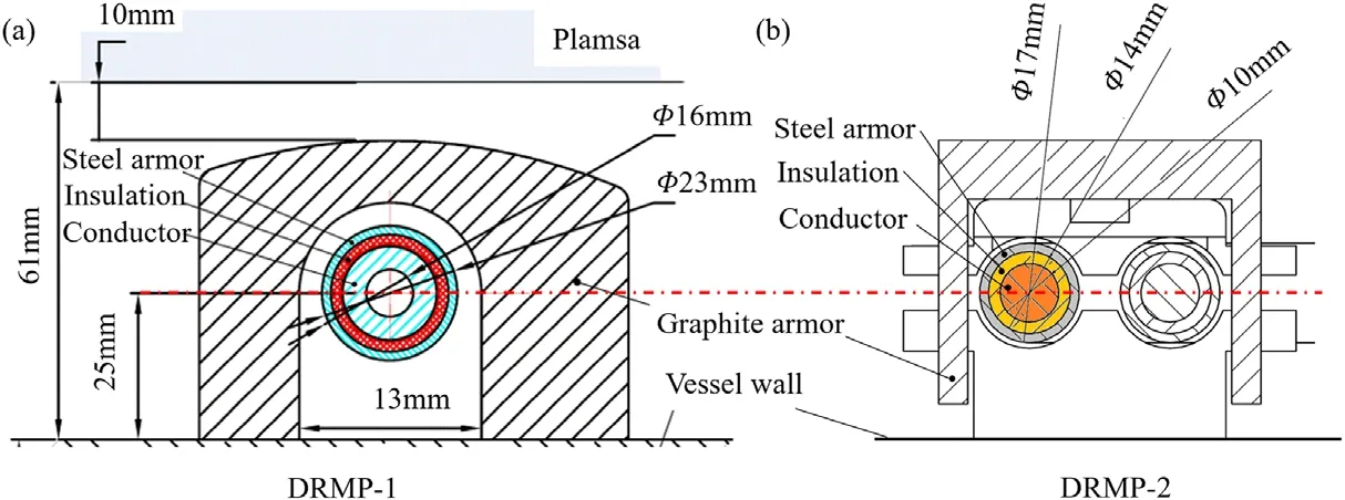
Figure 4. Cross-sections of the (a) DRMP-1 coil module and (b) the DRMP-2 coil module.
3.Simulation
The design of the two-turn coil structure was primarily guided by the constraints imposed by the limited in-vessel space.However,to assess the feasibility of this design,several issues need to be investigated,including the eddy effect,the lumped electrical parameters of the coil with respect to the power supply,the heat dissipation,and the electromagnetic load.Previous studies indicate that the electromagnetic load of the DRMP-1 coils has a considerable margin[18].Therefore,the electromagnetic load of the DRMP-2 coils is presumed to be within the stress limit and is not discussed here.To address the remaining issues,3D finite element simulations are employed below.
3.1.Electromagnetic analysis
With the increase in the coil’s turns,the inductance and resistance of the coil will increase.In the DC condition,the inductance of the coil is proportional to the coil’s area and approximately the square of the number of turns.Therefore,the inductance of the two-turn coil should be around four times that of the single-turn DRMP-1 coil.In the AC condition,the attenuation of the magnetic flux,resulting from the influence of eddy current in the vessel wall,leads to a decrease in the overall magnetic energy and a corresponding reduction in inductance.Regarding the resistance of the coil,it is inversely proportional to the cross-sectional area in the DC condition.In the AC condition,due to the skin effect,the resistance is inversely proportional to the effective cross-sectional area of the coil.The effective cross-sectional area is determined by the skin depth,which is expressed as:
where μ denotes the permeability and ρ denotes the resistivity.As the current frequency increases,the skin depth decreases,the effective cross-sectional area decreases,and the resistance increases.In addition,the heat generated by the eddy current on the vacuum chamber wall also indicates an increase in the system impedance,even though this heat is much smaller compared to the Joule heat of the coil.
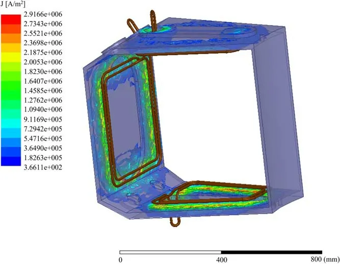
Figure 5.Model of simulation and the density of eddy currents.
Lumped electrical parameters,especially the inductance,have significant effects on the working frequency of the RMP power supply source.In addition,the amplitude and phase of the generated RMP are affected by the eddy current.The 3D finite element analysis was performed with Ansoft Maxwell to investigate these problems,as shown in figure 5.
In the 3D model,only the conductor of the coil was taken into account since there was no loop path on the stainless-steel armor.The conductor was artificially short-circuited outside the vacuum vessel for simulation requirements.Only the occupied port was included in the model,the eddy effect of other ports was neglected due to their far distances.The calculation region was a box that was 300%larger than the port in every direction and assigned the radiation boundary.A coil current of 1 kA was used and the calculated frequency range was from 10 Hz to 10 kHz.It can be observed that the eddy current is mainly concentrated on the vessel wall along the outline of the coil.
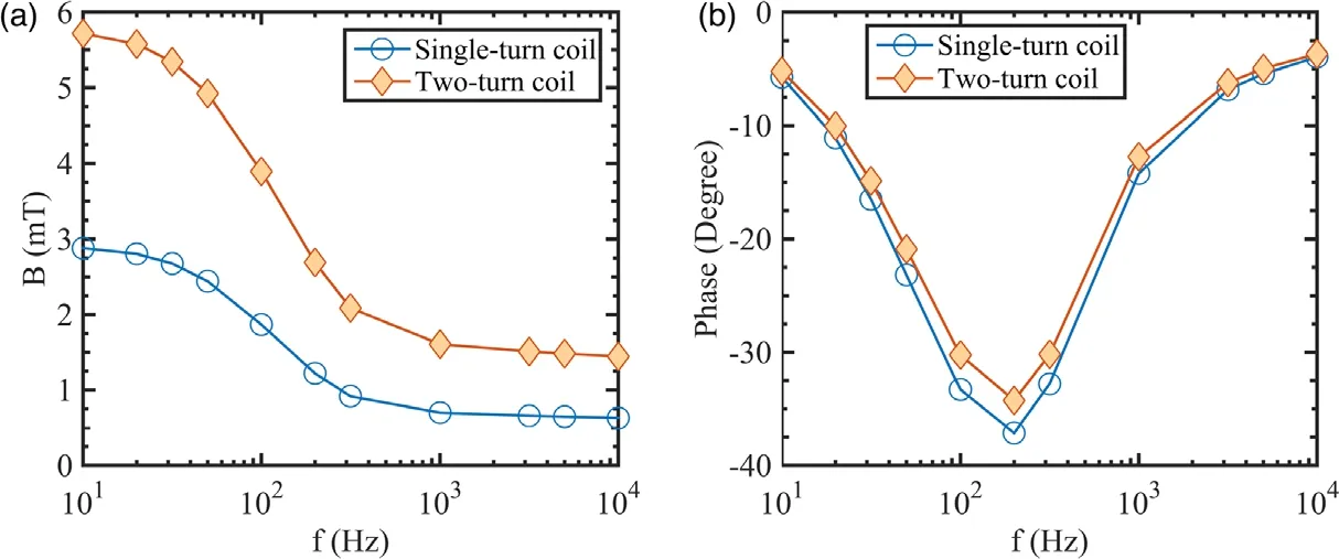
Figure 6.Variation of the field magnitude (a) and the phase (b) of the coil with the increase in frequency.
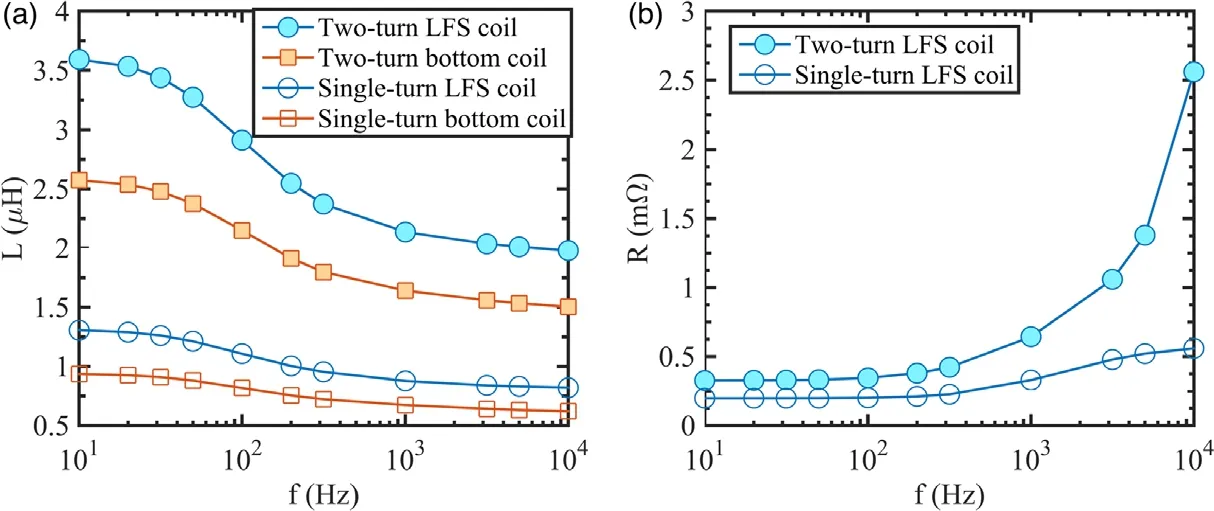
Figure 7.Variation of coil inductance (a) and resistance (b) with the increase in frequency.
Figure 6 shows the resulting magnetic field at the middle plane of the last closed surface.A variation of the magnitude and phase of the magnetic field with the increase of the current frequency was obtained.For comparison purposes,the DRMP-1 coil was also simulated and its results were provided.The magnitude of the magnetic field generated by the two-turn coil at 10 Hz is 5.7 mT,which is roughly twice that of the single-turn coil.Both of them decrease with increasing frequency.In the range of 10-1000 Hz,the amplitude decreases rapidly with the frequency.When the frequency is greater than 1000 Hz,the magnetic field amplitude remains almost unchanged.At 1000 Hz,the magnetic field amplitudes of the two coils are 1.6 mT and 0.7 mT,respectively.The eddy attenuation is approximately 28% compared with the magnetic field of 10 Hz.The magnetic field attenuation of the two-turn coil is slightly smaller than that of the single-turn coil.These two coils are similar in phase delay.When the frequency is greater than 1000 Hz,the phase delay is relatively small.It can be concluded from the above analysis that,considering the eddy current,the magnetic field of the twoturn coil is also approximately twice that of the single-turn coil,which is similar to the DC case.
Figure 7 shows the simulated coil resistance R and inductance L at various frequencies.As the frequency increases,the inductance decreases and the impedance increases.At the frequency of 10 Hz,the inductance of the two-turn LFS coil is 3.6 μH.The effective area of the bottom coil is small,its inductance is 2.6 μH.The inductance of the single-turn LFS coil is 1.3 μH.The inductance of the two-turn coil is 2.77 times that of the signal-turn coil,which is smaller than the square of the turn’s ratio due to the influence of the eddy current.The decrease in inductance with the increase in frequency is similar for single-turn and two-turn coils.The impedance of the two-turn coil at 10 Hz is 0.33 mΩ,where the impedance of the single-turn coil is 0.20 mΩ.However,the impedance of the two-turn coil rises rapidly when the frequency exceeds 3000 Hz,possibly due to the proximity effect,which becomes significant beyond this frequency and reduces the effective cross-sectional area.
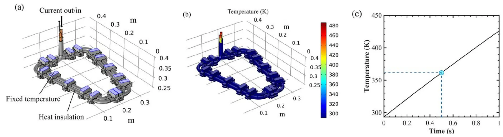
Figure 8.(a) Electro-thermal coupling 3D model,(b) the temperature distribution at 1 s,(c) time evolution of the coil temperature.

Figure 9.(a)Temperature distribution at 50 s with the initial temperature of 293.15 K,(b)time evolutions of the temperature of various layers of the coil with the initial temperature of 293.15 K,(c) time evolutions of the temperature of various layers when the initial temperature equals the final temperature.
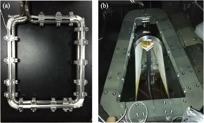
Figure 10.(a)The assembly of support parts for the LFS coil and(b)installation of the whole bottom coil module.
The AC power supply on the J-TEXT is a switching power supply based on the resonant inverter [19].The ACDC-AC rectifier and inverter module drive high-frequency and high-amplitude currents by resonance at the load end.This method requires a capacitor C in series with the load to ensure that the system works at the resonant frequency,satisfying the relationship LC=1/(2πf)2.The existing capacitors for the AC power supply match the operating frequencies of 1 kHz,2 kHz,3 kHz,4 kHz,5 kHz,and 6 kHz.Considering that the inductance of the two-turn coil is 2.77 times that of the single-turn coil,the maximum operating frequency of the two-turn coil is 3.5 kHz.This frequency is still comparable to the tearing mode frequency of several kHz[20],indicating that the two-turn coil can be effectively utilized for MHD control in the AC condition.
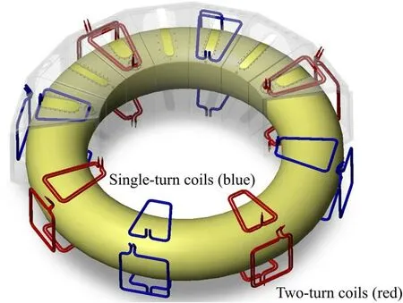
Figure 11.Layout of the in-vessel coils after the installation of twoturn DRMP-2 coils (red).Single-turn coils (blue) are the DRMP-1 coils [21].Reproduced from [21].© 2019 IAEA.CC BY 3.0.
3.2.Thermal analysis
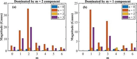
Figure 12. RMP spectra dominated by (a) m=2 components and (b) m=1 components.
During operation,the heat sources are the plasma radiation,the Joule heat from the eddy current on the vessel wall,and the Joule heat from the coil.Joule heat from the coil contributes the most to the coil’s temperature increase.Other heat sources are neglected in the following analysis.In the experiment,the maximum duration of each discharge is 1 s,the maximum energized time of the DRMP-2 is 500 ms,and there is a 5 min interval between each discharge.The heat is accumulated in 500 ms and dissipated in 5 min.Since excessive temperature increases can damage the insulation layer of the coil,it needs to be controlled.The temperature increase during operation is small for DRMP-1 coils [18].However,the DRMP-2 coils are more compact and do not have a water-cooling tube like the DRMP-1 coils,making heat dissipation more difficult.A multi-field coupled simulation was performed to demonstrate the temperature evolution of DRMP-2 coils using COMSOL MultiphysicsTM.
An electro-thermal coupling 3D model of the top DRMP-2 coil was built as shown in figure 8(a).All the screw holes on the model and the graphite armors are neglected for simplicity.The heat generated by the copper conductor is dissipated via the insulation layer,stainless-steel armor,Teflon ring,and finally to the vessel wall via the bottom of the support part.Regardless of the temperature increase of the vessel wall,all of the bottoms of the support part are set as fixed boundaries at 293.15 K.Other boundaries are set as heat insulation.At first,we should determine the temperature increase during the energized time of 500 ms.The coil current is set at an amplitude of 8 kA which is higher than the actual working current of 6 kA.To avoid introducing the magnetic field,the resistance of the copper conductor is modified to the AC impedance at 5 kHz based on the previous electromagnetic simulation.The simulation time is 1 s.The temperature distribution at 1 s is shown in figure 8(b),and the coil temperature is shown in figure 8(c).It can be observed that the heat is concentrated on the copper conductor of the coil.The heat dissipated into the insulation layer and stainless-steel armor is negligible in such a short period of time.The increase in temperature is linear with the simulation time and is 70 K at 500 ms.
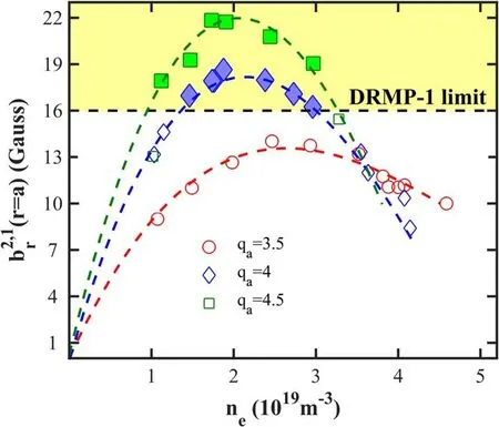
Figure 13.Density dependence of the m/n=2/1 field penetration threshold.Thresholds below 16 G can be obtained with DRMP-1(open markers),while thresholds beyond 16 G can only be obtained with DRMP-2 (closed markers).
Next,we should obtain the stable temperature of the DRMP-2 after several discharges.In the first step,the initial temperature of the coil module is set at 293.15 K,except for the copper conductor which has a temperature increase of 70 K.Figure 9(a) shows the temperature distribution at 50 s.The surface temperature of the steel armor is lower near the support part,indicating that the heat is dissipated via the support part.The time evaluations of the average temperature of the three layers are shown in figure 9(b).The final temperatures of the three layers at 300 s are almost the same at 303 K.The difference between the initial and final temperatures reflects the heat accumulation after one discharge.At the next step,the final temperature of 303 K is set as the initial temperature,and the temperature of the copper conductor is assigned with an increase of 70 K.The simulation is then run to update the final temperature.After five iterations,a stable temperature of 323 K is obtained at which the initial temperature equals the final temperature,as shown in figure 9(c).It can be observed that the peak temperature of the insulation layer is 343 K,which is lower than the softening temperature 363 K of the insulation material.The results for the LFS coil are similar to those for the top coil,as the capacity of heat dissipation is mainly determined by the distribution of the support parts.In conclusion,the two-turn DRMP-2 coil is feasible considering the heat dissipation.
4.Implementation of the DRMP-2 coils
The feasibility of the design for DRMP-2 coils has been demonstrated by the above analysis.According to the design,the DRMP-2 coils have been manufactured and successfully installed on the J-TEXT tokamak.Figure 10 shows photographs of the assembly.There are two steps for the installation of the DRMP-2 modules.The support part and graphite armor are assembled in the laboratory.Then,the assembled coil module was taken into the vessel and welded on the vessel wall.The assembly of support parts for the LFS coil is shown in figure 10(a).The installation of the entire bottom coil module is shown in figure 10(b).
The layout of in-vessel coils on J-TEXT after the installation of the DRMP-2 coils was updated as shown in figure 11 [21].The two-turn DRMP-2 coils and the singleturn DRMP-1 coils are evenly staggered in the toroidal direction.Discharge tests indicate that the coil can be fed with a current of up to 5 kA.Given that the maximum current of the DRMP coil is 6 kA,the amplitudes of the m/n=1/1,2/1,and 3/1 components generated with the application of both DRMP-1 and DRMP-2 are much higher than those with the application of DRMP-1 alone,where m is the poloidal mode number and n is the toroidal mode number.The Fourier component at the plasma edge (r/a=1) is shown in figure 12.With different connection strategies of the RMP coils,the RMP spectrum can be dominated by the m=2 or m=1 components.Compared to DRMP-1,the maximums of the present 1/1,2/1,and 3/1 components are 35 G,22 G,and 16 G,respectively,with an increase of 232%,244%,and 232%.The relative 2/1 field strengthis up to 0.175%.These results are of significant benefit to the J-TEXT experiments.
The application of the DRMP-2 system greatly extends the scope of RMP research on the J-TEXT tokamak.Benefiting from the enhancement of the RMP amplitude,a nonmonotonic density dependence of the field penetration threshold is found for the first time [22].Figure 13 shows the experimental results of the dependence of the plasma density on the 2/1 field penetration threshold.The field penetration threshold is taken as the 2/1 vacuum field component of the RMP at r/a=1 calculated from the coil currents.At safety factors qa=4 and 4.5,only incomplete data can be obtained with the DRMP-1 coils where the field penetration threshold is below 16 G (open markers).With the application of the DRMP-2 coils,the field penetration thresholds beyond 16 G were obtained in experiments(closed markers),confirming the non-monotonic dependence.In addition,the wiring strategy of DRMP-2 coils has been optimized.It further enhances the adjustability of the RMP phase,which enabled the investigation of the spectrum effects on the plasma [23].
5.Conclusions
A set of new in-vessel RMP coils called DRMP-2 has been designed for the J-TEXT tokamak,featuring compact two-turn saddle coils to overcome limited vessel space and plasma strike.Electromagnetic simulations of the DRMP-2 coils were performed to investigate the generated magnetic field and the electrical parameters.The main effect is that the maximum frequency of the new coil decreases to 3.5 kHz,which is still suitable for MHD control.An electro-thermal coupling simulation was performed to investigate the heat dissipation of the coils.It is shown that the maximum peak temperature of the insulation layer of the coil is 343 K,which is below its softening temperature.These simulations confirm the feasibility of the design of the DRMP-2 coils.Currently,the DRMP-2 coils have been installed on the J-TEXT tokamak.It has significantly enhanced the RMP amplitude and been widely applied in experiments.
Acknowledgments
This work is supported by Hubei Provincial Natural Science Foundation of China(No.BZQ22006),Fundamental Research Funds for the Central Universities (No.CZY20028),National Magnetic Confinement Fusion Energy R&D Program of China(No.2018YFE0309102),and National Natural Science Foundation of China (No.51821005).
ORCID iDs
猜你喜欢
数学小灵通(1-2年级)(2022年3期)2022-03-17
初中生学习指导·中考版(2021年4期)2021-09-10
考试与评价·七年级版(2020年6期)2020-11-02
考试与评价·七年级版(2020年3期)2020-11-02
考试与评价·七年级版(2020年5期)2020-10-29
考试与评价·七年级版(2020年1期)2020-10-23
初中生学习指导·中考版(2020年10期)2020-09-10
数学小灵通(1-2年级)(2018年9期)2018-11-19
山花(2015年22期)2015-02-20
 Plasma Science and Technology2023年11期
- Plasma Science and Technology的其它文章
- Preparation of highly efficient antibacterial non-woven by facile plasma-induced graft polymerizing of DADMAC
- Multiple chemical warfare agent simulant decontamination by self-driven microplasma
- Wet flashover voltage improvement of the ceramics with dielectric barrier discharge
- Experimental and numerical investigation on the uniformity of nanosecond pulsed dielectric barrier discharge influenced by pulse parameters
- Investigation of phase modulation and propagation-route effect from unmatched large-scale structures for Doppler reflectometry measurement through 2D full-wave modeling
- SOLPS-ITER drift modeling of neon impurity seeded plasmas in EAST with favorable and unfavorable toroidal magnetic field direction