
Topological resonators based on hexagonal-star valley photonic crystals
2023-12-02 09:22XinWan万鑫ChenyangPeng彭晨阳GangLi李港JunhaoYang杨俊豪andXinyuanQi齐新元
Chinese Physics B 2023年11期
Xin Wan(万鑫), Chenyang Peng(彭晨阳), Gang Li(李港), Junhao Yang(杨俊豪), and Xinyuan Qi(齐新元)
School of Physis,Northwest University,Xi’an 710127,China
Keywords: valley photonic crystals,triangular resonant cavity,topological edge state,unidirectional transmission
1.Introduction
The photonic quantum valley Hall effect, an analogy to the quantum valley Hall effect in condensed physics, has attracted intensive attention due to its unique properties in light manipulations.[1]Realizing the photonic quantum valley Hall effect requires the valley degrees of freedom.Generally,electromagnetic duality in valley photonic crystals or all-dielectric valley photonic crystals is used to introduce valley degrees of freedom in order to break the band degeneracy near the valleys (KandK′) by breaking spatial inversion symmetry.[2]These enable the realization of optical pseudospin-dependent,path-entangled transport analogous to the electronic valley Hall effect.Nowadays, valley photonic crystals with different structures based on the all-dielectric materials, e.g.,sublattice-broken honeycomb lattices,[3–5]triangular lattices with different-shaped scatterers,[6–8]stretched or compressed kagome lattices,[9,10]and waveguide arrays with alternating refractive indices,[11]have been proposed to breakC6symmetry while preservingC3symmetry.
The materials for realizing topological boundary states in optical systems are also quite diverse, ranging from anisotropic magneto-electric medium,[12,13]to dualanisotropic materials,[14,15]hyperbolic metamaterials,[16]and equivalent dual-anisotropic materials constructed with metal–air combinations.[17]Furthermore,isotropic all-dielectric photonic crystals have become widely used in recent years due to their simple fabrication and straightforward design of topological states based on the all-dielectric materials.Besides,such valley photonic crystals do not require external magnetic fields,or specific magneto-electric or dual-anisotropic materials,making them highly versatile for various applications.
The physical nature of valley topological edge states is mainly related to the following effects, such as the quantum Hall effect,[18,19]Floquet topological insulators,[20,21]quantum spin Hall effect,[18,21,22]or quantum valley Hall effect.[22,23]An external magnetic field was initially employed to break the time-reversal symmetry,[24,25]and then spatial inversion symmetry breaking was proposed to obtain the effects above.[26]The emergence of topological photonics provides possibilities for better control and manipulation of light.The topological edge states generated in such systems exhibit excellent properties,[27–30]including defect immunity,robust transmission around obstacles, and scattering suppression.Therefore, they have been extensively studied and hold great potential for applications in photonics integration[31,32]and optical communication fields.[33,34]
A microcavity[35]refers to a microresonator with a size in the order of wavelength.The study of microcavities has made it possible to integrate devices such as optical filters,[36]optical modulators/demodulators,and optical logic gates,enabling a wide range of applications in fundamental physics research and device applications.[37,38]However, micro-resonant cavities can suffer from increased losses due to fabrication defects and disorder.The combination of micro-resonant cavities with topological edge states in photonic crystals has been explored to suppress the backscattering, e.g., microcavities based on heterostructure,[39]two-dimensional photonic crystal line defect microcavities,[40]photonic crystal nanobeam microcavities,[41]and photonic crystal micro-ring refractive index sensors.[42]Besides, micro-resonators using traditional photonic crystals with defects[43,44]were also proposed.Nevertheless, all-dielectric topological photonic resonator with high-quality factor is still rarely reported.
In this study, we design aC3symmetric valley photonic crystal based on hexagrams and hexagons.By reducing the lattice symmetry and breaking the spatial inversion symmetry of the system,the degenerate Dirac points are suppressed,and the band gaps appear.Supercell structures with straight,Z-shaped,and Ω-type interface waveguides consisting of two valley photonic crystal units,which exhibit opposite but equal magnitudes of Berry curvature distributions, are constructed.When light propagates in the waveguide,the valley edge states emerge at the topological photonic waveguides, exhibiting unidirectional propagation and the suppression of backscattering.Furthermore, valley photonic crystal resonators are designed, and the quality factor is explored.The influence of resonator lengthLon the quality factorQis also investigated.Our findings of photonic crystal resonators may have potential applications in designing photonic crystal lasers, wavelength division multiplexers,and other photonic devices.
2.Valley photonic crystals
In this section,a novel all-dielectric two-dimensional valley photonic crystal is constructed.The photonic crystal is constructed by alternating between hexagrams and hexagons.The schematic diagram of a 2D all-dielectric valley photonic crystal is shown in Fig.1(a).The lattice constant is denoted asa=400 nm, and the dielectric constant of the dielectric rods isεd=14.The dielectric constant of the surrounding environment of the dielectric rods isεa=1.The composition of an individual dielectric rod is depicted in Fig.1(b),where the hexagon has a side length ofa1=0.225a, and the difference between the stretched hexagon and the hexagon is given by.The initial primitive cell without modification is depicted in Fig.1(c).The symmetry at the high-symmetry pointsK(K′) in the reduced Brillouin zone of this structure exhibitsC6symmetry.In previous studies,there have various methods to break theC6symmetry of the photonic lattices.This paper mainly discusses breaking spatial inversion symmetry by adjusting the distancedbetween the six-pointed star and the hexagon to achieve a structurally simple topological valley photonic crystal.
Due to the photonic lattice being composed of two sublattices, it is necessary to define two different types of dielectric rods in order to break the spatial inversion symmetry.The sizes of the modified dielectric rods are as follows:three hexagonal structure dielectric rods and three six-pointed star structure dielectric rods.After reducing the lattice symmetry,the structure of the primitive cell is shown in Fig.1(d)and labeled as valley photonic crystal 1 (VPhC1).If we exchange the positions of the hexagon and the six-pointed star,we can construct valley photonic crystal 2 (VPhC2), where the primitive cell structure is represented by the red structure in Fig.1(e).By keeping the geometric and material parameters of VPhC1 and VPhC2 unchanged, rotating the center of the VPhC1 primitive cell by 180◦yields VPhC2.Therefore,compared to VPhC1,it can be considered that VPhC2 simply exchanges the positions of the hexagon and the six-pointed star.Clearly,VPhC1 and VPhC2 have identical photonic band structures.
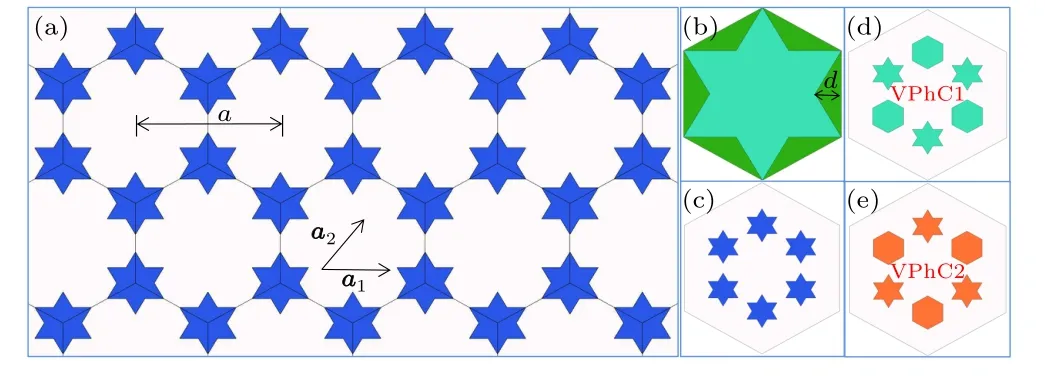
Fig.1.Structure diagram of two-dimensional all-dielectric valley photonic crystal.(a) Schematic diagram of the undistorted valley photonic crystal.(b) Schematic diagram of the dielectric rod structure.(c) Unit cell of the undistorted valley photonic crystal.(d)The green structure is a schematic diagram of VPhC1.(e)The orange structure is a schematic diagram of VPhC2.
In this study, we first consider the TM polarized mode.Scanning along the wave vector pathΓ–M–K(K′)–Γin the reduced Brillouin zone of the honeycomb lattice,the photonic band structure of the valley photonic crystal can be computed using the COMSOL Multiphysics.The computed results are shown in Fig.2.
From Fig.2(a), it can be seen that the first band (blue curve) and the second band (green curve) exhibit double degeneracy at the valley pointsKandK′,resulting in the closure of the band gap.This double degeneracy atKandK′is an inevitable consequence of the honeycomb lattice exhibitingC6symmetry when the two dielectric rods in the primitive cell are identical.This degeneracy is also known as the Dirac degeneracy.The linear dispersion relation formed around the Dirac points is referred to as the Dirac cone.The normalized frequency of the Dirac points is 0.278c/a,wherecis the speed of light in vacuum.The Dirac cone is protected by both time-reversal symmetry and spatial inversion symmetry.From Fig.2(b), when we consider VPhC1(VPhC2)as the scanned object,the first and second bands are gapped out,ranging from 0.249c/ato 0.283c/a.The Dirac cone is no longer protected by spatial inversion symmetry,leading to the disappearance of the double degeneracy.Besides,we also simulate with TE polarized mode and find that the photonic band gap could not be opened for the first and second bands,which is different from the work in Ref.[45].Therefore,only the TM polarized mode is considered in the following content.
Figure 2(c) shows the phase distribution of the first and second bands at theKpoint.The first band exhibits a counterclockwise phase distribution(indicated by the orange arrows)atK, with phase singularities primarily located at the center of the six-pointed star dielectric rods.On the other hand, the second band exhibits a clockwise phase distribution(indicated by the blue arrows) atK, with phase singularities located at the center of the hexagon dielectric rods.The phase variations are represented by left-handed circular polarization(LCP)and right-handed circular polarization (RCP).Similarly, Fig.2(d)analyzing the phase distribution at theK′point reveals that the phase distribution atK′is opposite to that atK.At theK′point,the phase of the first band exhibits a clockwise distribution,with phase singularities located at the center of the hexagon dielectric rods, while the phase of the second band exhibits a counterclockwise distribution,with phase singularities located at the center of the six-pointed star dielectric rods.
The two valley photonic crystals maintain their timereversal symmetry,and the total Chern number of a Brillouin zone is always zero.However,the Berry curvatures are locally nonzero at each valley and are opposite atKandK′valleys due to the quantum valley Hall effect.[46,47]To characterize the topological property of our system, we introduce valley Chern numberCV,[47]
which is calculated within half of the Brillouin zone around the valley.
The Chern number for each energy band can be expressed as
where the Berry curvatureFn(k)=∇×〈un(k)|i∇k|un(k)〉,andun(k) represents the eigenstate of then-th energy band.By modifying the integration region in Eq.(2)to half of the Brillouin zone for valleysKandK′, respectively, we can obtain the Chern numbersCKandCK′.
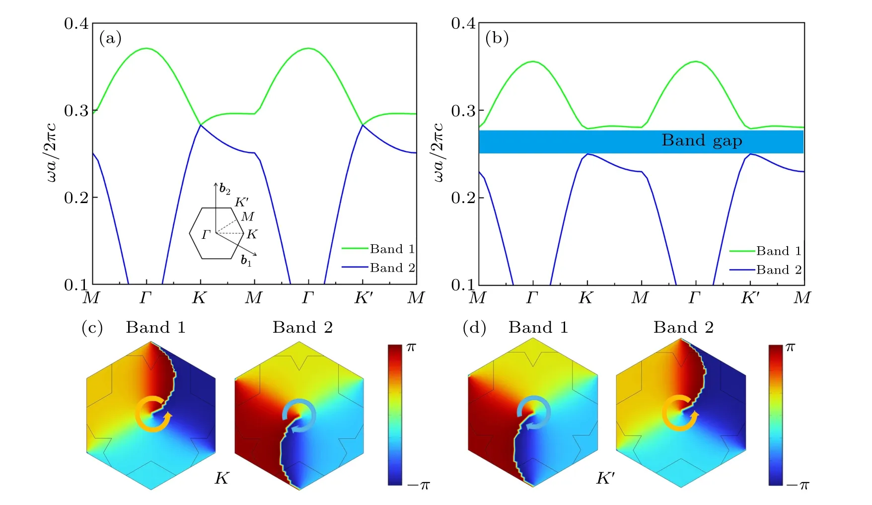
Fig.2.Band structure of the valley photonic crystals.(a) Band structure of the valley photonic crystal with C6 symmetry, illustrated with the first Brillouin zone diagram.(b) Band structure corresponding to the VPhC1 (VPhC2).(c) Phase distribution map at the K point.(d)Phase distribution map at the K′ point.

Fig.3.Topological edge states of the valley photonic crystals.(a)Schematic diagram of the structure of a valley photonic crystal.(b)Projected band diagram of the dispersion of edge states in the valley photonic crystal.The blue region represents the bulk bands of the valley photonic crystal,while the purple curve represents the dispersion of the edge states.
The results of Eq.(2)areCK,K′=±1/2 for VPhC1, andCK,K′=∓1/2 for VPhC2.Clearly, the valley Chern numberCVare +1 and-1, respectively, for VPhC1 and VPhC2.Therefore, as shown in Fig.3(a), the VPhC1 and VPhC2 are combined to form two different structures at the boundary, constituting a two-dimensional valley photonic crystal.By extracting a long strip-shaped supercell from the twodimensional valley photonic crystal,covering the width of the primitive unit cell of the photonic quasicrystal, we can calculate its projected band structure along thekxdirection, as shown in Fig.3(b).It displays the projected band structure of the valley photonic crystal, where the blue regions represent the bulk bands of the photonic crystal,and the band gaps exist between the bulk bands.A purple-colored dispersion curve of a boundary state appears within the band gap.The band group velocity at theKvalley is positive,indicating the presence of a forward-propagating topological edge state.On the other hand,the band group velocity at theK′valley is negative,indicating the presence of a backward-propagating topological edge state.
3.Transport properties of topological edge states in valley photonic crystals
Due to breaking the spatial inversion symmetry,combining two different valley photonic crystals can generate topologically protected boundary states, leading to various interesting physical phenomena.In this section,several topological photonic waveguides are designed based on valley photonic crystals that can exhibit topological valley boundary states.These waveguides are utilized to investigate their characteristics of one-way transmission and strong robustness.
3.1.Unidirection transmission of TM polarized mode
One of the significant advantages of the topological edge states in valley photonic crystals is their characteristic of unidirectional transmission.Valley coupling opens up a complete bandgap,where photons within a specific frequency range are prohibited from entering the photonic crystal.However,light waves of TM polarized mode can propagate along the boundaries of the valley photonic crystals, formed by the combination of VPhC1 and VPhC2, in different directions.This phenomenon gives rise to optical topological properties.
The valley photonic crystal is formed by combining VPhC1 and VPhC2 (see Fig.4(a)).Firstly, a TM polarized mode is incident from the left edge along the interface(zaxis)to obtain the transmittance.The frequency range of the light source is calculated to be within 175 THz and 215 THz based on the dispersion curve shown in Fig.3(a).The transmittance spectrum curve at the output port (right handside port)is shown in Fig.4(b).It can be seen from the diagram that the valley photonic crystal waveguide exhibits high transmittance across the entire wide spectral range of 183 THz to 208 THz.Secondly, we simulate the transmission of light beams when the light sources are incident at the center of the interface(the yellow pentagram) along thezaxis to excite the edge states(see Figs.4(c)and 4(d)).When a right-handed circularly polarized light(RCP)is used as the light source, the TM polarized mode component is excited and propagates along the positive direction ofzaxis; when a left-handed circularly polarized light(RLCP)is used as the light source,the TM polarized mode component is excited and propagates along the negative direction ofzaxis.For both two cases, the energy is primarily concentrated at the interface between VPhC and VPhC2 and the frequencies of light waves are 198.48 THz(0.257c/a).Circularly polarized states of different handedness will propagate in different directions within the combined topological insulator structure.In contrast, as shown in Figs.4(e) and 4(f),such a polarization-selective excitation phenomenon disappears at a higher or lower frequency, e.g., 188.17 THz or 200.35 THz.Therefore,this phenomenon is quite sensitive to light frequency,and only a single-frequency excitation is supported.We attribute such a polarization-selectively unidirectional transmission to the topological valley boundary states.In other words,the designed valley photonic crystal structure achieves unidirectional light transmission for different polarization states.

Fig.4.The unidirectional transmission and field distribution characteristics of the valley edge states in straight waveguides.(a) Schematic diagram of the straight waveguide in the valley photonic crystal, composed of VPhC1 (green region) and VPhC2 (orange region), with the position of the light source indicated by a yellow pentagram.(b) Transmittance curve.(c) Electric field intensity distribution diagram of the beam excited by right-handed circularly polarized light in the straight waveguide.(d)Electric field intensity distribution diagram of a beam excited by lefthanded circularly polarized light in a straight waveguide.(e)and(f)The distribution diagram of the electric field intensity in the straight waveguide of the beam excited by right-handed circularly polarized light at different frequencies.
3.2.Robustness
Another significant advantage of the valley photonic crystal edge states is their robustness against scattering.This section verifies the topological properties of the valley edge states at corners.Straight waveguides,Z-shaped waveguides,and Ω-shaped waveguides are designed based on the valley photonic crystals,as shown in Fig.5(a).A light source is placed at the left entrance port of the waveguide,and the frequency range of the light source remains between 175 THz and 215 THz.The Z-shaped waveguide contains two sharp corners,while the Ω-shaped waveguide contains four sharp corners, each with an internal angle of 60◦.

Fig.5.Robust transport and field distribution characteristics of energy valley boundary states in different waveguides.Panels(a)–(c)are straight waveguide, Z-shaped and Ω-shaped waveguide energy valley photonic crystal waveguide structure diagram and electric field intensity distribution.(d)Transmittance curves of different waveguides.
The transmission behavior of the boundary states in Zshaped and Ω-shaped waveguides is computed using COMSOL Multiphysics.Figures 5(a)–5(c) show the field distribution of the boundary states along the straight waveguide,Z-shaped bent waveguide, and Ω-shaped bent waveguide, respectively, at a light wave frequency of 192.36 THz.The following observations can be made from the electric field plots.(i) There is no scattering of the light wave towards the inner regions at each corner.(ii) The light wave’s energy remains relatively unchanged before and after each corner.This analysis indicates that the boundary states are topologically protected and can be transmitted almost losslessly in straight waveguides.In order to better demonstrate the transmission behavior of light waves in the Z-shaped and Ω-shaped waveguides,Fig.5(d)presents the transmission spectra of the straight waveguide,Z-shaped waveguide,and Ω-shaped waveguide at the output ports.By comparing the transmission spectra of the Z-shaped and Ω-shaped waveguides with those of the straight waveguide, it is observed that the transmission spectra in the Z-shaped and Ω-shaped waveguides almost overlap entirely with the transmission spectra in the straight waveguide within the bandgap range, and the transmission rates are also high.The topological boundary states transmitted at the sharp corners are also protected by topology,enabling efficient propagation through the bending corners of the waveguide along the predetermined path, demonstrating strong robustness.
4.Triangular ring resonator based on valley photonic crystal
The pursuit of optical devices is towards high integration and low energy loss.However,traditional optical devices suffer from losses caused by backscattering,such as waveguides and resonators.The topological boundary states of valley photonic crystals possess immune transmission properties against defects and impurities.Therefore,combining them in the design of optical devices holds excellent research value.
Photon crystal resonators are a crucial component in photonics integration, and their performance evaluation relies on two essential parameters: resonator volume and quality factor.The resonator volume reflects the degree of miniaturization of the photonic crystal device, with smaller volumes indicating higher integration levels.The quality factor characterizes the resonator’s ability to confine photons,with higher values indicating stronger photon confinement within the resonator.
In this section, a topological triangular cavity is constructed using the edge states of the valley topological crystal.The achieved topological cavity differs significantly from traditional photonic crystal nanocavities.The valley boundary states are topologically protected and insensitive to the geometric structure,which provides more possibilities for designing and fabricating resonators on the photonic crystal platform.As an essential branch of topological photonics,the valley photonic crystal exhibits stable transmission characteristics.Its relatively simple structure makes it suitable for designing compact on-chip optical devices.
The resonator is depicted in Fig.6(a),surrounded by the boundaries of the VPhC1 structure outside the cavity and the VPhC2 structure inside the cavity.The topologically protected valley photonic crystal triangular resonator has three corners.To investigate the resonator’s performance, random point sources were placed near the labeled positions on the boundary of the resonator to excite all resonant modes.The frequency range of excitation was from 175 THz to 215 THz.Five models with different resonator lengths of 15a,18a,23a,26a, and 29awere constructed to investigate the influence of resonator length on the quality factor.As shown in Fig.6(b),it was discovered that light can be confined to the topological edge states of the photonic crystal with energy valleys.As depicted in Fig.6(c), at a frequency of 199.21 THz, light can propagate steadily along the boundary state with minimal losses.However, as shown in Fig.6(d), at a frequency of 207.31 THz,the electric field distribution of light becomes non-uniform,resulting in increased losses.

Fig.6.Topological valley photonic crystal triangular ring resonator.(a) Schematic diagram of a valley photonic crystal triangular resonator.(b) Electric field distribution of a valley photonic crystal resonator.(c) Light field distribution diagram with a frequency of 199.21 THz.(d)Light field distribution diagram with a frequency of 191.67 THz.(e)Q factor of the topological triangular ring resonator.(f)Highest Q factor among different cavity lengths.
As shown in Fig.6(e), a resonant cavity with a specific cavity length (side length 23a) is studied, and theQfactor exhibits a trend of initially increasing and then decreasing with the increase of the resonant frequency.At a specific frequency,the resonant cavity reaches its highestQfactor,which falls within the frequency range of the valley photonic crystal boundary state.Within this frequency range,topological edge states in the valley photonic crystal provide topological protection, resulting in reduced energy loss in the resonant cavity.As shown in Fig.6(f),comparing the maximumQfactors of the resonant cavities with five different cavity lengths, the highest value is 12531,which occurs at a cavity length of 23acorresponding to a frequency of 203.61 THz.The frequency from pointAto pointEalso gradually increases.The reasons for the decrease in the quality factor of the resonant cavity with increasing cavity length differ.When the side length of the resonant cavity is too short,the light waves at the cavity boundary will couple with each other when the light waves propagate along the resonant cavity,increasing loss.When the side length of the cavity increases,that is,when the size of the cavity increases, theQfactor of the cavity continues to increase before 24a.Continuing to increase the side length will lead to a decrease in theQfactor.The reason for this phenomenon is mainly due to the fact that when light is transmitted in the cavity,the loss it experiences is related to the propagation length it experiences.When the cavity length becomes longer,the loss will lead to a decrease in the energy stored in the cavity.According to the definition,theQfactor equals the energy stored in the cavity divided by the energy lost per unit of time.As theQfactor decreases,the propagation loss of the boundary mode will increase.
5.Conclusion
We have proposed a method to achieve a hexagonal-star valley photonic crystal.By alternating the sizes of hexagram scatters,the degeneracy between the high-symmetry pointsKandK′is broken.A valley photonic crystal is realized by combining two sets ofC3symmetric hexagonal star photonic lattices.Supercell structures with straight,Z-shaped,and Ω-type interface waveguides consisting of two valley photonic crystal units, which exhibit opposite but equal magnitudes of Berry curvature distributions,are designed.Simulation results show that the topological edge states can be achieved at the interface of the supercell structure, and the robust and stable transmission, particularly at corner bends, further confirms the highly unidirectional light transmission.Based on these findings, a topological triangular resonant cavity is simulated using supercell structures.The maximumQfactor of the resonant cavity reaches 1.25×10⁴for the cavity length of 23aand frequency of 203.61 THz.Our work riches the content of valley topological photonics and may have potential applications in topological lasers,photonic integrated circuits,and optical modulation devices.
Acknowledgment
Project supported by the National Natural Science Foundation of China(Grant No.1217040857).
猜你喜欢
控制与信息技术(2022年1期)2022-12-02
今日农业(2022年15期)2022-09-20
大众文艺(2019年3期)2019-01-24
学校教育研究(2018年1期)2018-10-21
辽金历史与考古(2018年0期)2018-03-21
散文诗(2017年6期)2017-07-12
扬子江诗刊(2015年3期)2015-11-14

- Chinese Physics B的其它文章
- Optimal zero-crossing group selection method of the absolute gravimeter based on improved auto-regressive moving average model
- Deterministic remote preparation of multi-qubit equatorial states through dissipative channels
- Direct measurement of nonlocal quantum states without approximation
- Fast and perfect state transfer in superconducting circuit with tunable coupler
- A discrete Boltzmann model with symmetric velocity discretization for compressible flow
- Dynamic modelling and chaos control for a thin plate oscillator using Bubnov–Galerkin integral method