
Quantum algorithm for minimum dominating set problem with circuit design
2024-02-29 09:16HaoyingZhang张皓颖ShaoxuanWang王绍轩XinjianLiu刘新建YingtongShen沈颖童andYukunWang王玉坤
Chinese Physics B 2024年2期
Haoying Zhang(张皓颖), Shaoxuan Wang(王绍轩), Xinjian Liu(刘新建),Yingtong Shen(沈颖童), and Yukun Wang(王玉坤),2,†
1Beijing Key Laboratory of Petroleum Data Mining,China University of Petroleum,Beijing 102249,China
2State Key Laboratory of Cryptology,P.O.Box 5159,Beijing 100878,China
Keywords: quantum algorithm,circuit design,minimum dominating set
1.Introduction
Quantum computing is an interdisciplinary field that combines principles in modern physics and computer science.In recent years, quantum algorithms have received considerable attention from researchers,[1,2]attracted by their unique properties such as superposition,[3]interference,[4]and entanglement,[5]which enable exponential or square order speedups compared to classical algorithms.Numerous studies have explored quantum algorithms,[1,2,6–15]highlighting their potential for solving various computational problems.
The minimum dominating set problem,particularly on an undirected graph,is a well-known problem that belongs to the class of problems known to be NP-complete,[16]where NP stands for non-deterministic polynomial.The concept of a dominating set has applications in various real-life scenarios,offering a versatile mapping to a range of problems.Examples include the optimization of school bus routing, wireless sensor network management,urban traffic route planning,and several other domains.[17]The problem seeks to find a subset of vertices in a graph that dominates all other vertices.In other words,each vertex in the graph must either belong to the dominating set or be adjacent to at least one vertex in the set.Various classical algorithms,such as greedy algorithm[18]and genetic algorithm,[19]have been proposed to solve this problem.However, these approaches often yield approximate solutions and are highly dependent on the chosen strategy.Exact solution algorithms also exist,[20–26]but they suffer from high computational complexity.
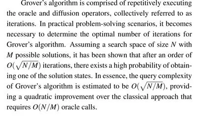
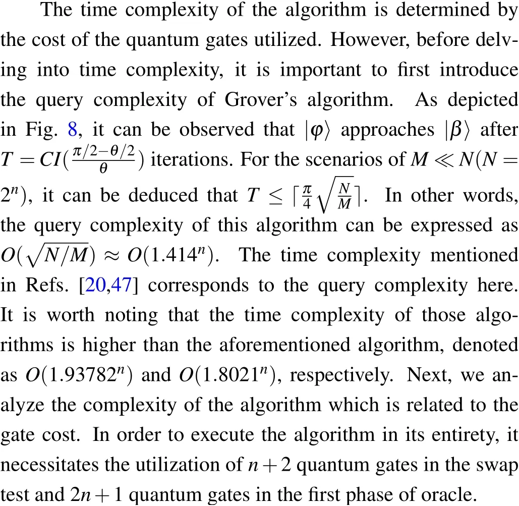
Grover’s search algorithm has emerged as one of the most widely studied quantum algorithms, with applications in diverse problem domains.[27–30]This algorithm employs Grover iterations, which comprise two essential components: the oracle and the diffusion operator.The oracle identifies the target states, while the diffusion operator amplifies the amplitudes of these states.By performing measurements,the algorithm can identify the target states representing solutions to the problem with a high probability.Compared to classical algorithms, Grover’s algorithm offers a computational advantage by requiring onlyiterations to find a solution in an unsorted database of sizeN, significantly outperforming the lower bound ofO(N)evaluations required by classical methods.
In the field of NP-complete problems, Grover’s algorithm is a popular solution that can solve many problems, including the graph coloring problem,[10–13]the shortest path problem,[14]and the 0–1 knapsack problem.[15]Therefore,leveraging the accelerated properties of quantum algorithms,applying Grover’s search algorithm to the dominating set problem is an attractive proposition.However, a challenge arises in the minimum dominating set problem due to the unknown number of solutions, making direct use of original Grover’s search algorithm infeasible.In recent years,there has been substantial research focusing on enhancing Grover’s algorithm for various applications.[31–37]These proposed methods have limited efficacy when it comes to solving the minimum dominating set problem.For instance, the approaches described in Ref.[31] can only identify the dominating set and do not provide a guarantee of finding the minor dominating set.Moreover, the design complexity associated with the phase gate in Ref.[32] presents challenges.As an alternative,Aaronson and Rall presented an approximate counting algorithm in Ref.[33], which estimates the number of target solutions within a set without relying on the quantum fourier transform, resulting in a relatively complex implementation.Therefore,a universal method is needed to estimate the number of iterations for Grover’s algorithm.
To address this challenge,we propose a swap test method to estimate the number of iterations required by calculating the fidelity between the initial state and the state of the algorithm after one iteration.By exploiting fidelity information,we can determine the number of iterations for Grover’s algorithm.Using the swap test and Grover’s algorithm,we design a quantum algorithm for the minor dominated set and subsequently obtain the minimum dominated set through classical post processing.Our proposed method ensures the attainment of an approximate exact solution and facilitates a simple circuit design.We outline the algorithm framework and systematically design the oracle circuit,diffusion operators,and swap test circuit, employing achievable quantum gates.The query complexity and qubit cost of this method areO(1.414n) andO(n)when the number of vertices in a graph isn.
The structure of this paper is as follows.Section 2 provides an overview of quantum circuits, Grover’s algorithm,and dominating sets.In Section 3, we present a detailed description and performance analysis of our algorithm circuit.We implement the method using qiskit and demonstrate its effectiveness with two examples in Section 4.Finally,Section 5 concludes the paper.
2.Preliminaries
In this section,we provide readers with some background knowledge to better understand our method.We describe qubits and quantum gates[38]in the context of quantum circuits,then provide a concise overview of Grover’s algorithm,and the dominating set problem in graph theory.
2.1.Quantum circuit
In quantum computing,all algorithms can be realized by quantum circuits which are composed of qubits and quantum gates.
Qubits The fundamental unit of a quantum circuit is the quantum bit, known as a qubit, which is the quantum counterpart of classical bits used in classical computing.In the realm of physics, a qubit can be realized as a superposition of any two distinguishable quantum states, typically denoted as|0〉 and|1〉.These quantum states can be physically represented based on the properties of certain physical systems,such as the spin of an electron or the energy level state of an atom.In a quantum circuit,a qubit can exist in a superposition of multiple states, exemplified asα|0〉+β|1〉, whereαandβare complex numbers, representing the probability amplitudes of the respective states.This property enables quantum circuits to simultaneously process multiple possibilities, potentially conferring a computational advantage.There are two types of qubits, the first type is data qubits which are used to encode the input or output of a quantum algorithm.The other is the ancilla qubits that are used to store interim or temporary results during the execution of the algorithm.
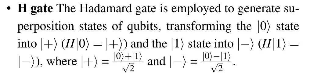
Quantum gates Quantum gates are employed to enact all operations within a quantum circuit, serving as operations or evolutions within physical systems capable of modifying the state of qubits.Distinct quantum gates exert diverse influences on qubits.In our algorithm, we utilize several specific quantum gates, including the Hadamard (H) gate, the controlled-NOT (CNOT) gate, the Toffoli gate, and the multiple control Toffoli(MCT)gate.
• CNOT gate It is a two-qubit gate where the upper qubit acts as the control qubit and the lower qubit functions as the target qubit.When the gate is applied, it transforms the tensor product state of the two qubits,denoted as|a〉⊗|b〉 into|a〉⊗|a ⊕b〉, where the⊗is used to represent the tensor product in quantum mechanics,indicating the combined state of two or more qubits and the⊕represents the bitwise XOR(exclusive OR)operation between bit values,indicating the result of applying XOR to the binary values of the bits.
• Toffoli gate This is a three-qubit quantum gate.There are two control qubits and a single target qubit.When it is applied,|a1a2〉⊗|b〉 can be transformed to|a1a2〉⊗|a1a2⊕b〉.
• MCT gate This gate is similar to the Toffoli gate,which is ann-qubit quantum gate.By applying it,|a1...an〉⊗|b〉can be transformed to|a1...an〉⊗|a1...an ⊕b〉.Here,a,b,ai ∈{0,1}represent binary values.We collectively refer to the CNOT gate, Toffoli gate, and MCT gate as controlled gates.In this context,a visual notation is employed,utilizing a black dot to signify that when the control qubit is in the state|1〉, it induces a change in the target qubit.Conversely,for ease of representation, a white dot is used to signify that when the control qubit is in the state|0〉,it likewise influences the state of the target qubit.In current quantum devices, basic quantum logic gates,such as single-qubit gates and CNOT gates, are implemented using control techniques to manipulate individual qubits and establish interactions between them.These gates are realized on various quantum platforms,including superconducting qubits,trapped ions,and hybrid systems combining different types of qubits.
2.2.Grover’s algorithm
Currently, Grover’s algorithm has been implemented on various quantum computing platforms including IBM Quantum Experience, Rigetti Forest, and Microsoft Quantum Development Kit.These platforms provide programming languages and tools for users to utilize Grover’s algorithm for tasks such as unstructured database search.Except for the simulation platforms, there have been several experimental demonstrations of Grover’s algorithm on different quantum hardware platforms, such as superconducting qubits and trapped ions.Although these implementations are still limited in terms of the number of qubits and the level of noise, they represent significant progress towards achieving practical applications of Grover’s algorithm on quantum hardware.
The quantum circuit framework employed in Grover’s algorithm is visually depicted in Fig.1.It comprises two fundamental components:the oracle and the diffusion operator.The oracle plays a pivotal role in this quantum search algorithm as it is responsible for altering the phase of the target states.It is worth noting that different problem instances necessitate distinct oracle configurations, tailoring the algorithm to specific problem domains.The diffusion operator, alternatively known as the inversion about the average operator,serves as a critical amplification step within Grover’s algorithm.Its primary function is to enhance the amplitude of the target states,thereby elevating the likelihood of measuring the desired solution.This enhancement is achieved through a process that reflects the average amplitude across all states, accentuating those that deviate from this average.The initial setup involves the utilization of the firstnqubits as data qubits, responsible for encoding the problem’s solution space.Meanwhile, the final qubit,known as the ancilla qubit,is dedicated to effectuating phase alterations within the target states.Grover’s algorithm encompasses four distinct stages,namely,initialization,Hadamard transformation,oracle,and diffusion operator.
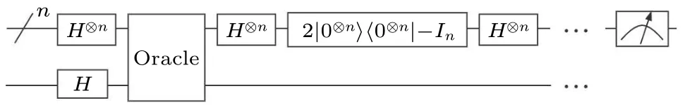
Fig.1.Generalized circuit of Grover’s algorithm.
InitializationIn the initialization stage, the data qubits are initialized in the state|0〉.The ancilla qubit, on the other hand, is initialized in the state|1〉, preparing the system for computation.
Hadamard transformationHadamard operations are applied to both the data and ancilla qubits,the operation facilitates the creation of superposition states,endowing all possible solutions with an equal probability amplitude.
and the ancilla qubit is transformed from|1〉to|-〉.
OracleThe oracle, a problem-specific gate, is pivotal in marking the correct solution with a negative phase.It perturbs the phases of the target states in a manner tailored to the problem’s nature.Let the solution set of the problem be denoted asS.The oracle can be represented as a functionfdefined as
Thus,the effect of the oracle can be defined as
where|x〉nrepresents the data qubits, and|q〉 represents the ancilla qubit.
Diffusion operatorThe diffusion operator increases the probability amplitude of the correct solution by adjusting the phase of the target state,which effectiveness arises from its underlying quantum mechanical principles.It is fundamentally based on the concept of quantum interference.In quantum systems,probabilities are determined by the complex amplitudes associated with each possible outcome.These amplitudes can interfere constructively or destructively.If a quantum state is viewed as a vector in a high-dimensional space, the diffusion operator will rotate this vector closer to the target state.
As we can see in Fig.1,the operation described as
is the diffusion operator.During this phase, the amplitude of the marked states is enhanced, while the probability amplitudes of the unmarked states are reduced.As a result, when the data qubits are measured, the marked states are obtained with a significantly higher probability.This enables an efficient identification and extraction of the desired marked states from the superposition of all possible states.
2.3.Dominating set
Giving an undirected graphG=(V,E), there is a vertex subsetS ⊆V,withS ̸=∅.For∀v ∈V,eithervbelongs toS,or at least one adjacent vertex ofvbelongs toS.Such anSis called a dominating set ofG.The vertices which belong toSare called the dominant vertex,and other vertices are called the non-dominant vertex.The number of dominant vertices for the dominating setSis defined asγ(S).If any true subsets of the dominating setSare non-dominating,Sis called a minor dominating set.The sets with the smallestγ(S)in all minor dominating sets are called minimum dominating sets.The minimum dominating and minor dominating sets of a graph are not unique,but theγ(Si)of all minimum dominating sets is equal.For a more comprehensive description of the dominating set problem,we refer the reader to the books.[39,40]Figure 2 illustrates an example with three vertices, where the dominating sets can be identified as{A},{A,C},{A,B},{B,C},{A,B,C},the minor dominating sets are{A}and{B,C}, and the final minimum dominating set is{A}.
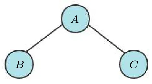
Fig.2.An undirected graph G=(V,E)with three vertices.
3.The proposed approach for the minimum dominating set problem
This section presents the algorithmic implementation for identifying the minimum dominating set in undirected graphs.Figure 3 illustrates the step-by-step process of the algorithm, which aims to leverage quantum algorithms to accelerate the search for minor dominating sets.Through the measurement of the quantum circuit, a set of quantum states describing the states of the vertices(whether they are dominant or non-dominant) can be obtained.Within this set, the minimum dominating set corresponds to the smallest number of dominant vertices.However, the measured result represents a combination of minor dominating sets, necessitating classical post-processing.The overall idea of the quantum algorithm is shown in Algorithm 1,which shows how the search algorithm finds the minor dominating set.In the subsequent sections, we introduce Algorithm 1 in detail.

Fig.3.The process of finding minimum dominating set.The overall algorithmic process entails employing a quantum algorithm to obtain the minor dominating set of a graph, subsequently employing this minor dominating set as input for a classical algorithm,and finally outputting the minimum dominating set of the graph.
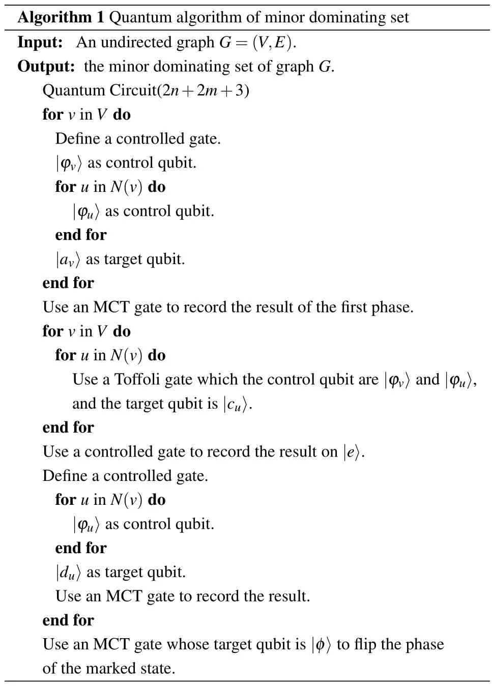
Algorithm 1 Quantum algorithm of minor dominating set Input: An undirected graph G=(V,E).Output: the minor dominating set of graph G.Quantum Circuit(2n+2m+3)for v in V do Define a controlled gate.|ϕv〉as control qubit.for u in N(v)do|ϕu〉as control qubit.end for|av〉as target qubit.end for Use an MCT gate to record the result of the first phase.for v in V do for u in N(v)do Use a Toffoli gate which the control qubit are|ϕv〉and|ϕu〉,and the target qubit is|cu〉.end for Use a controlled gate to record the result on|e〉.Define a controlled gate.for u in N(v)do|ϕu〉as control qubit.end for|du〉as target qubit.Use an MCT gate to record the result.end for Use an MCT gate whose target qubit is|φ〉to flip the phase of the marked state.
3.1.The algorithm idea
We present a novel approach for identifying the minor dominating set in an undirected graphG=(V,E) composed ofnvertices.Each vertex in the graph can be classified into one of two categories: dominant or non-dominant.Consequently, the search space for the minor dominating set problem,denoted asS,encompasses 2npossible vertex sets,where S={Si}i=1,...,2n.
The quantum algorithm module is divided into two phases: the first phase focuses on searching all dominating sets,and the second phase focuses on searching all minor dominating sets within the obtained dominating sets.
3.1.1.Circuit design for the minor dominating set problem using Grover’s algorithm
The primary task of this research endeavor entails the design of a quantum circuit capable of implementing the aforementioned ideas.Figure 4 shows the cases of the quantum circuit employed for addressing the minor dominating set problem.The algorithm proposed in this study builds upon Grover’s algorithm as its foundation.Subsequently,we delve into an elaborate examination of the five sequential steps constituting the algorithm.
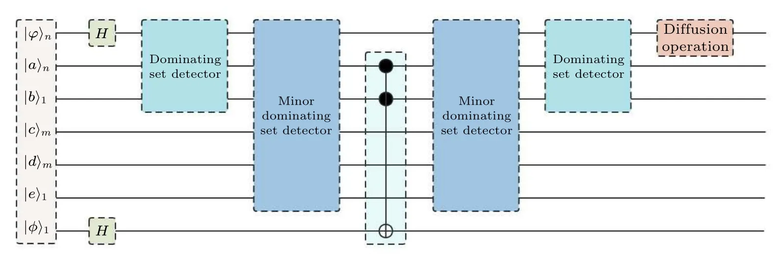
Fig.4.The general framework of applying Grover’s algorithm to the minor dominating set problem,the most important parts are the dominating set detector and minor dominating set detector.
3.1.2.Circuit setup
It is possible to classify the quantum bits into seven distinct categories based on their specific functions within the circuit, as shown in Fig.4.The effect of different qubits is introduced as follows.
•|ϕ〉n: The minimum dominating set problem necessitates the utilization ofnqubits,denoted by|ϕx〉,wherex ∈{1,2,...,n}, in order to represent the search space associated with this problem.
•|a〉nand|b〉1: The state|a〉 comprisesnqubits and serves as a repository for storing the outcome of judgments obtained during both the first and second phases outlined in Subsection 3.1.On the other hand,the state|b〉 encompasses a single qubit solely designated for recording the outcomes associated with the first phase.For the purposes of representation, let us define the dominant set of the problem asZ.Consequently, the state|b〉can be mathematically defined as follows:
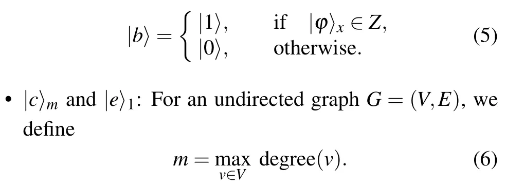
The state|c〉 comprisesmqubits and serves as storage for information related to the fulfillment of the first judgment condition in the second phase of the method proposed in Subsection 3.1.Specifically, if|c〉x=|1〉forx ∈{1,2,...,m}, it indicates that the condition has been satisfied.Additionally, a single qubit denoted as|e〉is utilized to record the results corresponding to the state|cx〉,x ∈{1,2,...,m}.
•|d〉m: The state|d〉 is employed to assess whether one of the neighboring vertices of the current vertex can be dominated by other vertices in the dominating set when the current vertex is changed to a non-dominating vertex.If|dx〉=|1〉 forx ∈{1,2,...,m}, it signifies that this condition holds true for at least one adjacent vertex.In the event that|d〉m=|1〉m, it indicates that all adjacent vertices of the current vertex can be dominated by other vertices in the event of the current vertex being changed to a non-dominating vertex.In other words,the current vertex satisfies the second judgment condition in the second phase of the method proposed in Subsection 3.1.
•|φ〉:It is utilized for the purpose of flipping the phase of marked states and requires only a single qubit.
3.1.3.Initialization
The initialization process is as follows:
3.1.4.Hadamard transformation
The Hadamard transformation is applied to both the data qubits and the phase reversal ancilla qubits.The transformation can be defined as follows:
In our representation,the state|1〉signifies that the current vertex is classified as a dominant vertex, while the state|0〉 represents that the vertex is categorized as a non-dominant vertex.We take|101〉 as an example, where the two|1〉 means that verticesAandCare dominant vertices,and the middle|0〉means that vertexBis a non-dominant vertex.After Hadamard transformation on the data qubits,the search space will be encoded into the circuit.
3.1.5.Oracle
Before introducing oracle, in order to better understand the algorithm,it is necessary to introduce two related concepts,namely garbage qubit and mirror.When a qubit undergoes an operation and is not reset to its initial state, it becomes unusable and is referred to as a garbage qubit.To prevent this,a mirror is employed to restore such qubits to their original states for subsequent use,thereby eliminating a large number of circuit costs.Consequently, the oracle circuit presented in this research exhibits symmetry.
The proposed quantum circuit is partitioned into two distinct phases,aligning with each respective stage elucidated in the proposition of the algorithm described in Subsection 3.1.Quantum logic gates are commonly used to express quantum operations.In graphG=(V,E) withnvertices, we require the Toffoli gate, MCT gate, and CNOT gate to complete the circuit.Referring to Fig.4,the details are given as follows:
Dominating set detector For everyv ∈V,we useN(v)to represent the adjacent vertices ofv,and|ϕw〉to represent one vertex set ofw=v∪N(v).When|ϕw〉=|0,...,0〉is satisfied,the set comprisingw=0,...,0 is identified as non-dominating set.We mark these dominating sets by introducing an ancilla qubit|av〉.Specifically,we introduce a controlled gate,where|ϕw〉serves as the control gate,and|av〉as the target bit.When|ϕw〉=|0,...,0〉is satisfied,the target qubit|av〉undergoes a bit flip operation.
After all the vertices have been done, we employ a controlled gate to map the marked results onto the ancilla qubit|b〉and restore all|av〉v∈Vfor subsequent procedures.The controlled gate takes|av〉v∈Vas the control qubits and|b〉 as the target qubit.In the case of combining non-dominated sets,no operations are applied to|b〉.Conversely,when|b〉undergoes a transformation from|0〉 to|1〉, it indicates that the current set is a dominating set.Thus, if|b〉 is in the state|0〉, it signifies that the current set is a non-dominating set.Otherwise,the current set is identified as a dominating set.
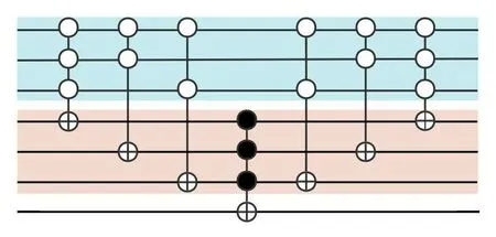
Fig.5.Dominating set detector.The circuit is to mark the set that can dominate vertex A,B and C in the given undirected graph in Fig.2.
Taking the undirected graph in Fig.2 as an example, its corresponding circuit diagram is shown in Fig.5.Following the application of theH⊗3,the state|ϕ〉3represents the superposition of the search space spanning from|000〉to|111〉.The initial controlled gate, referred to as an MCT gate, is utilized to mark the sets in which the vertexAis a non-dominating vertex.
Notably, when all the control qubits are in the state|0〉, signifying that vertexAcannot be dominated in the current set, the target qubit|a〉 is transformed from|1〉 to|0〉.Similar operations are performed on the remaining vertices.Only when all the marked qubits remain un-flipped, namely|a1,a2,a3〉=|1,1,1〉,|b〉is transformed from|0〉to|1〉.The outcome|b〉=|1〉 serves as a marker for the dominating set.Consequently,the state|ϕ1,ϕ2,ϕ3,b〉assumes the superstition of|0000〉,|0010〉,|0100〉,|0111〉,|1001〉,|1011〉,|1101〉,and|1111〉.The resulting dominating sets are|011〉,|100〉,|101〉,|110〉, and|111〉, where|b〉=|1〉.These states correspond to{B,C},{A},{A,C},{A,B}, and{A,B,C}.The three controlled gates on the right side of the circuit serve to restore the qubits of the ancillary circuit|av〉.
Minor dominating set detector This process is divided into two phases.
Forv ∈V,setk=degree(v)to denote its degree.We can employkcontrolled gates to determine whether the vertexvcan be dominated after it becomes a non-dominating vertex.For eachu ∈N(v),the control qubit of each controlled gate is|ϕw〉, wherew=v ∪uand the target qubit is|cu〉.Then, introduce another ancilla|e〉,which serves as a marker to record the sets in whichvcan be dominated even after it becomes a non-dominating vertex.This is accomplished by employing a controlled gate, where|cu〉 serves as a control qubit.The resulting state|e〉=|1〉signifies that the corresponding sets are non-minor dominating sets,as vertexvcan still be dominated even after it becomes a non-dominating vertex.
For each adjacent vertexuof the current vertex, we can employ a controlled gate to determine whetherucan be dominated after it becomes a non-dominating vertex.The control qubit of the controlled gate is|ϕw〉,wherew=u∪N(u)/v,and the target qubit is|du〉.If the target qubit|du〉is in|1,...,1〉,it indicates that the adjacent vertices of the current vertex are already in the dominating set.Therefore,each adjacent vertex of the current vertex can be dominated even after the current vertex becomes a non-dominating vertex.
We use an MCT gate to record the result of the states after performing the above operations,where|d〉and|e〉are control qubits,and|av〉is the target qubit.If|av〉is in|1〉,it signifies that this set is a minor dominating set.After all vertices in the set are judged,we employ another MCT gate to mark the minor dominating sets and flip their corresponding phases.The control qubits of the MCT gate are|a〉and|b〉,while the target qubit is denoted as|φ〉.
Taking Fig.2 as an example,its judgment circuit diagram for vertexAis shown in Fig.6.The initial three controlled gates are utilized to assess the dominant ability of the vertexAsubsequent to its removal from the dominating set.The third controlled gate is used to map the result onto the ancilla|e〉.Specifically,it turns the dominating set as well as ancilla into
wheree=1 serves as an indicator denoting the set in which vertexAcan still be dominated even after its removal from said set.
The fourth and fifth controlled gates are used to judge whether the verticesBandC(all adjacent vertices of vertexA)can still be dominated when the vertexAbecomes a non-dominating vertex.The sixth controlled gate maps the result to|a〉.The five controlled gates on the right side are used to restore the initial qubit of|c〉,|d〉,and|e〉.Specifically,
Therefore,after the judgment operations based onAand its adjacent vertices,the set|111〉which is a non-minor dominating set is marked.
The aforementioned judgment operations are sequentially applied to verticesA,B,andCwithin the overall circuit.The circuit diagram is depicted in Fig.7.We use an MCT gate whose target qubit is|φ〉 to flip the phase of the minor dominating sets, and the controlled gates on the right side symmetrical about the MCT gate are used to restore the ancilla circuit.The controlled gates situated to the right of the MCT gate exhibit symmetry and serve the purpose of restoring the ancilla circuit.This restoration ensures that the qubit value of the ancilla circuit remains consistent with its state prior to executing the algorithm in subsequent Grover iterations.The final marked minor dominating sets comprise|011〉and|100〉,corresponding to{B,C}and{A},respectively.
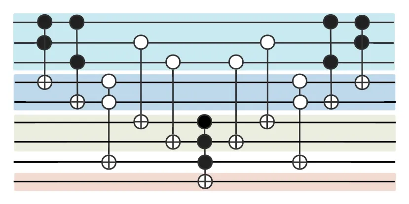
Fig.6.Minor dominating set detector.The circuit is to mark that a dominant set containing vertex A (the first line) is still a dominant set when vertex A is eliminated from the dominant vertex.If so,A can be eliminated in the dominant set.Similar circuits will be executed in sequence for the remaining vertices to check whether this vertex can be eliminated.Finally,turn the dominant set into a minor dominating set.
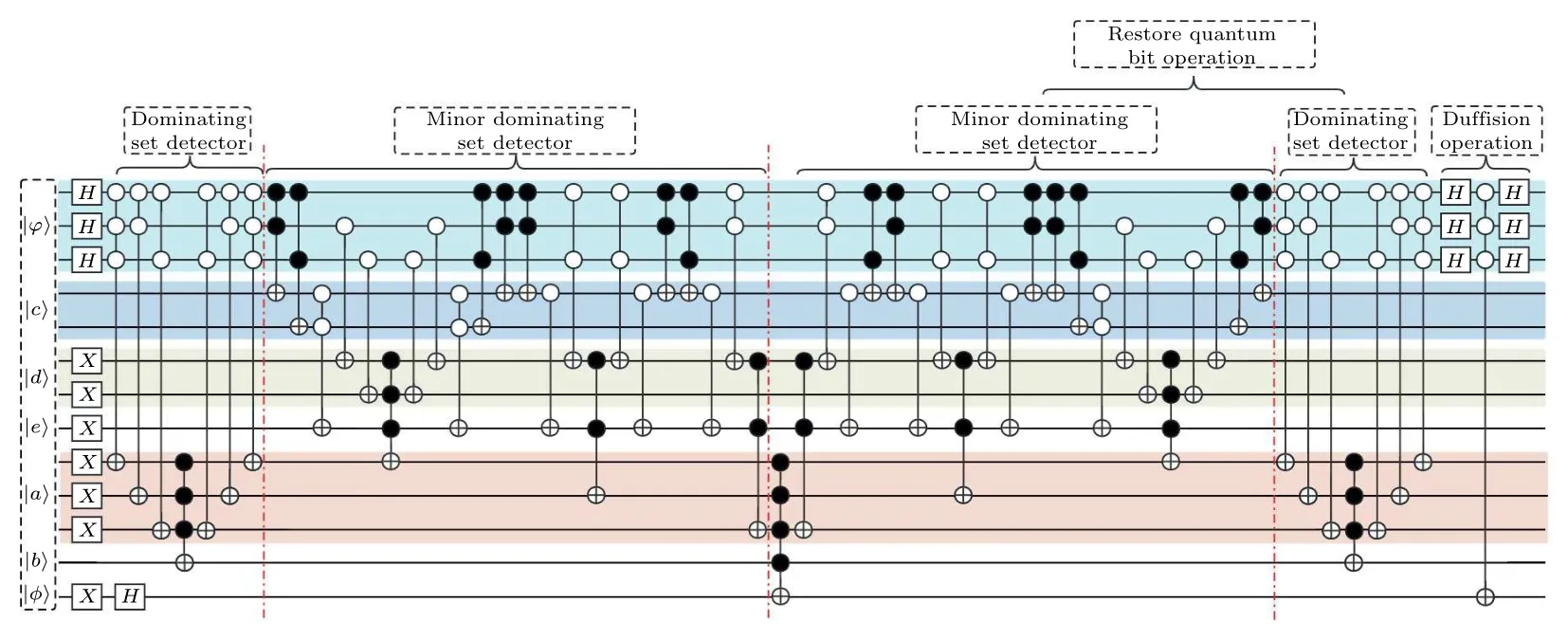
Fig.7.The circuit for dominating set problem of the given three-vertex undirected graph.It includes two modules,i.e.,the dominating set detector module and the minor dominating set detector module.The dominating set detector module is employed to identify all dominating sets within the graph, while the minor dominating set detector module is utilized to identify the minor dominating sets within the graph.Lastly,the diffusion operation module is applied to amplify the identified collection of minor dominating sets.
3.1.6.Diffusion operation
The diffusion operation, which forms an integral part of the Grover iteration, can be conceptualized as a reflection of the state[as described in Eq.(1)].The operation of this part is
which equals 2|X〉〈X|-I.
The circuit diagram depicting the complete process of finding the minor dominating set for Fig.2 is illustrated in Fig.7, considering the incorporation of multiple measurements.By performing multiple measurements on the data qubits,we are able to identify the set that contains the fewest dominating vertices, known as the minor dominating set.However, before conducting measurements, an important issue that needs to be addressed is to determine the optimal iteration numbers.In the case of minor dominating set problems,the number of potential solutions remains unknown,rendering the direct application of original Grover’s search algorithm impractical.
From the practical implementation perspective, theHgate,CNOT gate,and PauliXgate in the quantum circuit designed above are basic gates and can be directly implemented on quantum computers.However, the circuit also involves multi-controlled gates.For these controlled multi-qubit gates,we can typically decompose them into combinations of basic gates and entangling operations,with implementation methods varying based on the specific quantum platform being used.There have been numerous studies on the decomposition of multi-controlled gates.[38,41–45]The seminal work by Barencoet al.[38]introduced a technique to decompose an (n+1)-qubit controlled single-qubit unitary gate into a combination of single-qubit gates and controlled-Xgates.However,the resulting circuit depth and the number of quantum gates employed exhibit quadratic scaling with the number of qubits.Saeediet al.[41]proposed a linear-depth,quadratic-size quantum circuit for realizing ann-qubit Toffoli gate using controlled-rotation gates.Notably,this method does not require an ancilla qubit.Daet al.[42]shows that ann-qubit controlled single-qubit unitary gate can be decomposed into a circuit with a linear depth of single-qubit and CNOT gates.Vartiainenet al.[43]decomposes multiple controlled gates through the use of Gray code.Heet al.[44]proposes a work that only requiresO(n)number of general resources for ann-qubit Toffoli gate.Valeet al.[45]decomposes multiple controlled gates into single-qubit unitary gates and controlled-Xgates,similarly,no auxiliary qubits are required.This approach enables achieving linear scaling in both circuit depth and the number of quantum gates.
3.2.Estimation of the number of iterations of Grover’s algorithm
We propose a more effective method that uses a swap test to estimate the number of iterations.In the subsequent sections,we provide a comprehensive and detailed description of the estimation process.The visualization of one iteration of Grover’s algorithm is shown in Fig.8,where|α〉is the superposition state of the non-target solution and|β〉is the superposition state of the target solution.The rotated angle of the one iteration is denoted asθ,which is the value related to the number of iterations.Figure 9 shows the swap test circuit.Taking|ϕ〉andG|ϕ〉as the input of the swap test,the output state is expressed as follows:
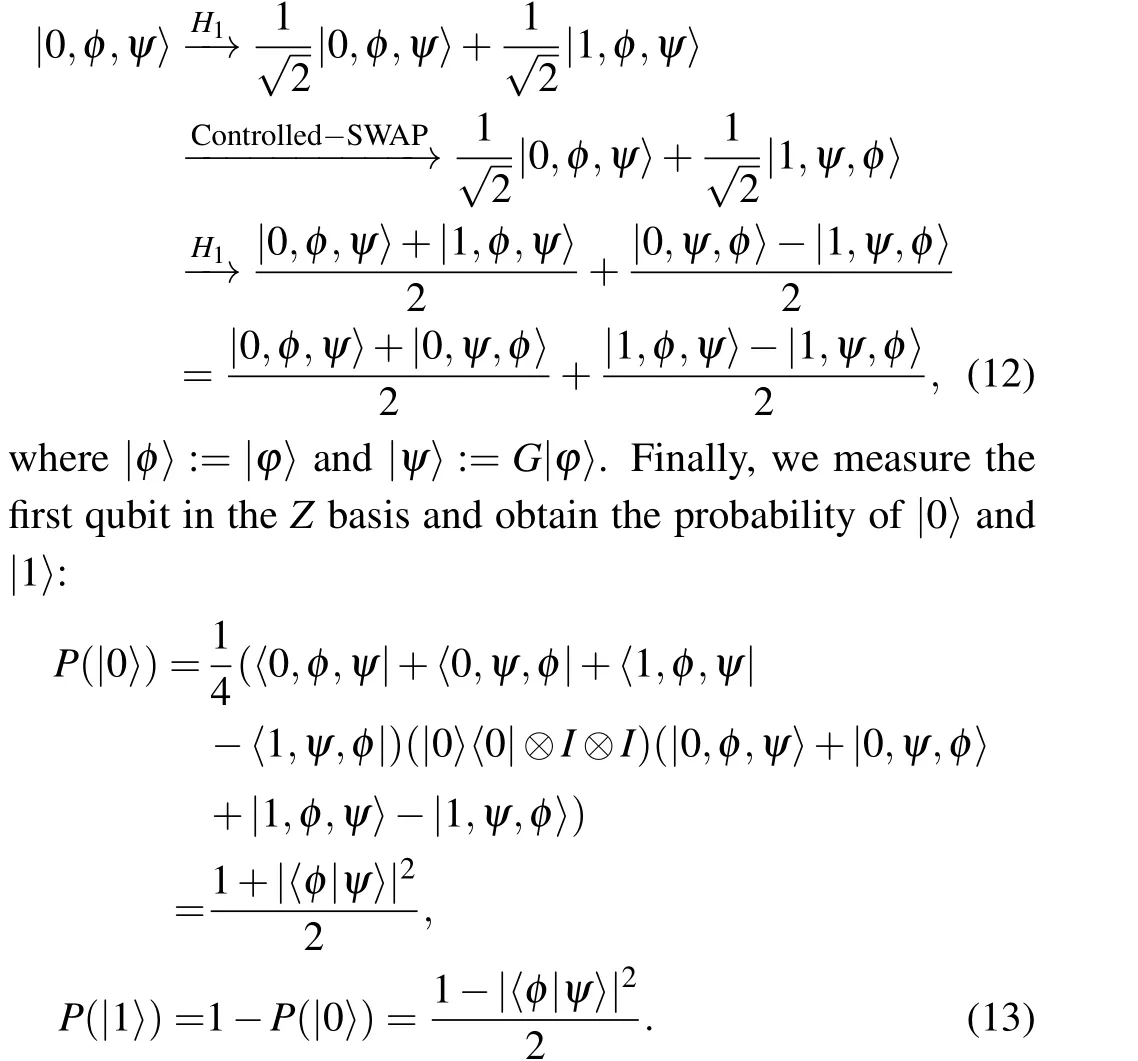
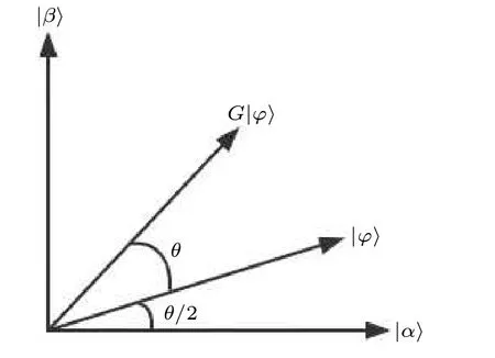
Fig.8.One iteration visualization of Grover’s algorithm.
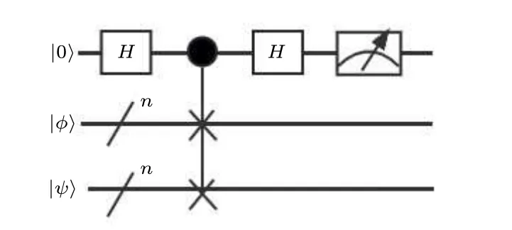
Fig.9.General quantum circuit of swap test.
3.3.Circuit cost estimation
We describe the overall design process of our quantum algorithm, and conduct a detailed analysis of the circuit cost associated with the algorithm,as presented in Table 1.For an undirected graphG=(V,E) withnvertices, we analyze the cost from space complexity and time complexity.
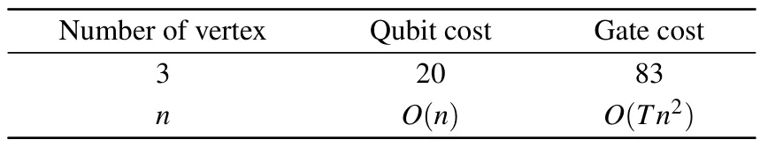
Table 1.Cost analysis of algorithm.
The cost of the qubit in the algorithm is called space complexity.The oracle we design requiresndata qubits and 2m+n+3 ancilla qubits when the maximum degree ism.In addition, for|ϕ〉 ofnqubits, the swap test requires 2n+1 qubits.Therefore,we require a total of 2m+4n+4 qubits.
The number of quantum gates required by the second phase of the oracle is related to the degree of each vertex in the undirected graph, rendering it infeasible to provide a precise numerical value.In order to assess the worst-case scenario, we consider a fully connected graph, where the gate cost amounts to 4n2-3n+1.Additionally, the restoration of ancilla qubits necessitates an equivalent number of gates as the first and second phases.Within the diffusion operator,the incorporation of 2n+1 quantum gates is essential.Consequently,afterTiterations,a total of quantum gates amount to(T+1)(8n2+6)+(n+2),which is expected to yield superior results in the majority of cases.
After getting the minor dominating set through the algorithm, we can use the classical computer to get the minimum dominating set withO(M) whereMis the number of minor dominating sets obtained by the quantum algorithm.However,this cost has little impact on the overall cost.
The complexity of this algorithm is more optimistic than that of classical algorithms.In the classical algorithms,Fominet al.proposed a theory in Ref.[25]that focuses on reducing the search space and accelerating the algorithm’s efficiency.However, this approach is limited to graphs with a minimum vertex degree of 3.The query complexity associated with it is denoted asO(1.93782n).Grandoni, on the other hand,established a correlation between the time complexity of the minimum set cover problem and the minimum dominating set problem in Ref.[47],this method by leveraging dynamic programming techniques reduces the complexity of the minimum set cover problem,the time complexity of the minimum dominating set problem was also improved toO(1.8021n).Although these methods yield accurate results, their elevated time complexity poses a challenge for current computing capabilities.Consequently,reducing time costs through the utilization of quantum algorithms holds significant promise.
3.4.The success rate of algorithm
The success rate is one of the important indicators to measure whether the algorithm is excellent.As far as this method is concerned, one of the root causes of the error is the process of calculatingθ.According to the cost analysis in the above section, the cost of calculatingθfor the swap test circuit is negligible in terms of the overall cost.Consequently,by conducting multiple measurements,the cumulative impact on accuracy can be disregarded.
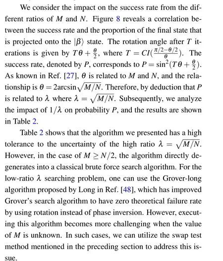
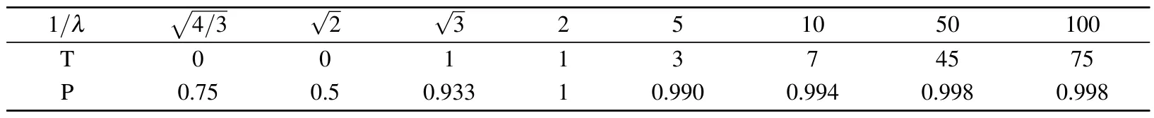
Table 2.Relationship between λ and P.
4.Simulation of minimum dominating set algorithm
We simulate the quantum algorithm using a Python software package called Quantum Information Science Kit(Qiskit).The software package uses Open QASM or Open Quantum Assembly Language developed by IBM and is used in all IBM quantum hardware.As examples for our simulation, we consider two undirected graphs with three vertices and eight vertices,respectively.
4.1.Simulation of three-vertex graph
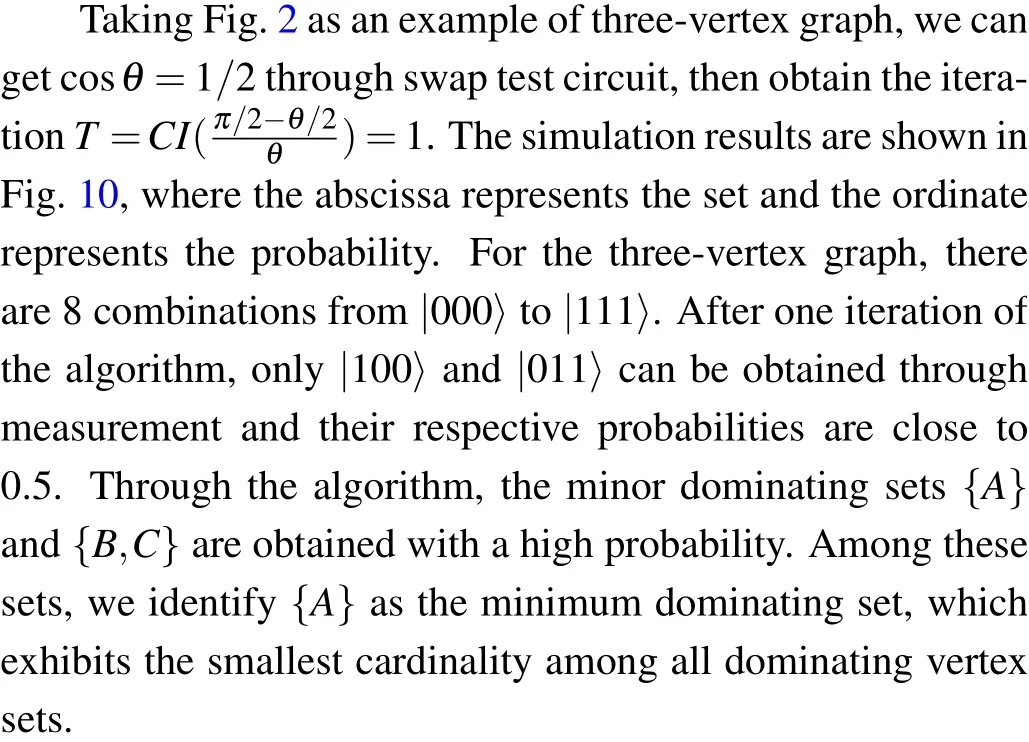
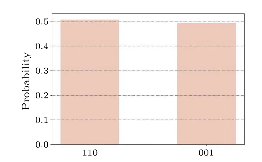
Fig.10.Using qiskit to simulate the graph shown in Fig.2,two minor dominating sets are obtained through measurement, with a probability of 0.5.
4.2.Simulation of eight-vertex graph
We randomly generate a graph with eight vertices as shown in Fig.11.From the swap test circuit, the angle is calculated with cosθ= 228/256, then we get the iteration ofT= 3 according toθ.Figure 12 shows the simulation results after 2000 times measurements.As we can see, the dominating sets are obtained with a high probability.The dominating sets corresponding to the measurement result are{A,C,D},{A,B,C,E},{B,F},{D,F},{A,C,G},{B,C,G},{C,E,G},{A,F,G},{E,F,G},{B,C,D,H},{C,E,H},{A,F,H},{E,F,H},and{C,D,G,H}.Among these sets,the minimum dominating sets are identified as{B,F}and{D,F}.
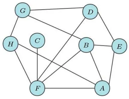
Fig.11.An undirected graph with eight vertices generated randomly.
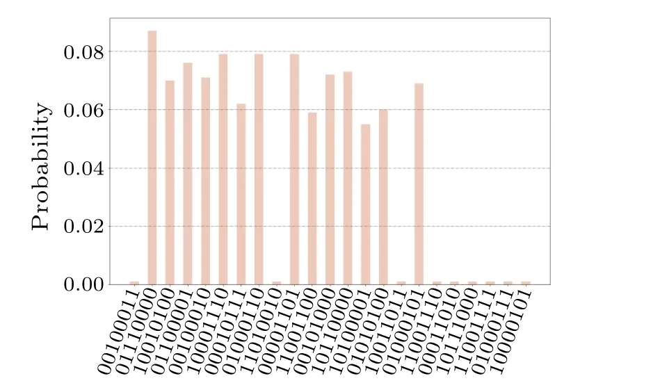
Fig.12.The simulation result of the graph shown in (a).After measurement,the probability of each target state is about 0.07.
To verify the correctness and effectiveness of the algorithm for any graph,except the simulations of the above threeand eight-vertex graphs,we also performed experimental verification on graphs with different numbers of vertices, particularly 2,4,5,6,and 8 vertices.The results of the experimental verification are presented in Table 3.It can be observed that the accuracy of the algorithm is close to 100 percent, indicating that it performs well in correctly identifying graph properties.Additionally, the running time of the algorithm is reasonable,considering the complexity of the task.However,due to limitations in computer memory capacity,we were only able to verify graphs up to 8 vertices.Based on the results presented in Table 3, it can be concluded that the circuit running time and accuracy of the algorithm are acceptable for the tested graphs.Furthermore, the current experimental results show that the proposed algorithm outperforms the method described in Ref.[47].We are confident that the algorithm will yield even more promising results as computer memory capacity expands.
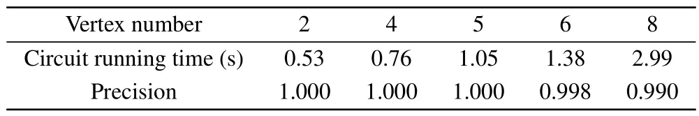
Table 3.Execution efficiency of undirected graphs with different vertex numbers.
5.Conclusion
In this paper, we present an automated quantum algorithm utilizing Grover’s search algorithm to solve the problem of finding the minimum dominating set in undirected graphs.Comparative analysis with classical brute force search demonstrates a quadratic improvement in query complexity, rendering our algorithm more efficient and accurate than existing classical approximation algorithms.Our designed oracle exhibits a gate cost and circuit cost ofO(n2) andO(n), respectively.Furthermore, we propose a novel method for estimating the number of iterations by leveraging fidelity obtained from the swap test.This method features a simple circuit design, easy implementation, and broad applicability to any problem addressed by Grover’s algorithm.Experimental validation supports the superior performance of our method in accurately determining the optimal number of iterations.
To demonstrate the effectiveness and efficiency of our algorithm, we conduct simulations using Python and the qiskit package developed by IBM.We showcase its performance on undirected graphs with three and eight vertices, showcasing the algorithm’s accuracy in obtaining minor dominating sets with high probability.Subsequently, classical postprocessings are employed to transform these minor dominating sets into minimum dominating sets, significantly reducing the search space and enabling accurate solutions within a short time.All the quantum circuits in this study are manually designed.However, future research should explore the automatic design of quantum circuits for a given graph.In this work,we employ a simulation platform to verify the accuracy of our proposed methods.In the future, we plan to optimize the quantum circuit implementation and conduct experiments on real quantum computers.Additionally,we will investigate the impact of hardware noise on the performance of the circuit implementation.
Acknowledgments
Project supported by the National Natural Science Foundation of China (Grant No.62101600), the Science Foundation of China University of Petroleum, Beijing (Grant No.2462021YJRC008), and the State Key Laboratory of Cryptology(Grant No.MMKFKT202109).
猜你喜欢
Chinese Physics B(2022年12期)2022-12-28
作文小学中年级(2022年9期)2022-09-08
石油沥青(2022年3期)2022-08-26
广东教学报·教育综合(2022年45期)2022-05-05
小天使·一年级语数英综合(2020年5期)2020-12-16
小天使·一年级语数英综合(2019年4期)2019-10-06
美与时代·美术学刊(2018年8期)2018-11-23
江海学刊(2018年2期)2018-04-04
美与时代·美术学刊(2018年10期)2018-01-25

- Chinese Physics B的其它文章
- Unconventional photon blockade in the two-photon Jaynes–Cummings model with two-frequency cavity drivings and atom driving
- Effective dynamics for a spin-1/2 particle constrained to a curved layer with inhomogeneous thickness
- Genuine entanglement under squeezed generalized amplitude damping channels with memory
- Protected simultaneous quantum remote state preparation scheme by weak and reversal measurements in noisy environments
- Gray code based gradient-free optimization algorithm for parameterized quantum circuit
- Symmetric Brownian motor subjected to L´evy noise