Investigation of flow separation control on an airfoil usingDBD plasma actuators
2011-06-15 01:26WANGXunnianWANGWanboHUANGYongZHANGXinHUANGZongbo
实验流体力学 2011年4期
WANG Xun-nian,WANG Wan-bo,HUANG Yong,ZHANG Xin,HUANG Zong-bo
(1.School of Aeronautics,Northwestern Polytechnical University,Xi'an 710072,China;2.China Aerodynamics Research and Development Center,Mianyang Sichuan 621000,China)
Investigation of flow separation control on an airfoil usingDBD plasma actuators
WANG Xun-nian1,WANG Wan-bo2,HUANG Yong2,ZHANG Xin2,HUANG Zong-bo2
(1.School of Aeronautics,Northwestern Polytechnical University,Xi'an 710072,China;2.China Aerodynamics Research and Development Center,Mianyang Sichuan 621000,China)
Influence of plasma actuators on the flow separation control of NACA 0015airfoil was investigated in an open-circuit low-speed wind tunnel.Particle Image Velocimetry (PIV)technology was applied to visualize the modification of the flow structure over the airfoil by the plasma actuators.Lift and drag were measured by a five-component strain gauge balance to investigate the separation control effect of the actuator voltage and excitation frequency.The results show that the leading-edge plasma actuators are effective in controlling the flow separation over the airfoil at low wind speeds.The maximum lift coefficient and stall angle are increased by 11%and 6deg respectively at the free-stream velocity of 20m/s.However,at a given flow state,there exists threshold values for both the actuator voltage and excitation frequency on the actuators.The threshold values are different with the changing attack angles.At the higher attack angles,the plasma actuator's authority must be increased due to the much stronger flow separation on the airfoil.
plasma;flow control;actuator;flow separation
0 Introduction
The maximum lift and stall characteristics of a wing decide many performance aspects of an aircraft,including takeoff and landing distance,maximum and sustained turn rates,climb and glide rates,and flight ceiling[1]etc.Therefore,how to increase the maximum lift and improve stall characteristics is an important issue for aerodynamics.
As an important branch and research frontier of aerodynamics,flow control is to improve aerodynamic characteristics,such as reducing drag and increasing lift.Methods of flow control can be divided into two types:passive flow control that modifies the main flow structure and active flow control that modifies the local flow by introducing external energy.Active flow control includes blowing and suction,micro-jet[2],synthetic jet[3],plasma actuation,micro-electro-mechanical systems(MEMS)[4]etc.
Plasma technique has received much attention in recent decades due to its prospective applications in flow control.The popular DBD(Dielectric Barrier Discharge)plasma actuator consists of two electrodes that are located on the surface separated by a dielectric material.A high-voltage AC supplied to the electrodes causes the air in their vicinity to weakly ionize.The ionized air(plasma)in the presence of the electric field gradient produced by the electrodes results in a body force vector acting on the external flow that can induce steady or unsteady velocity components.In this way,it can effectively control boundary layer transition and separation,significantly improve lift-to-drag ratio and stall angle of the aircraft.
In recent years,there have been a great deal of researches focusing on plasma flow control due to the advantage of no moving parts,quick response,very low mass,low input power and low parasitic drag when not in operating,such as boundary layer control[5-6],lift augmentation and separation control for airfoils[7-12],low-pressure turbine blade separation control[13]etc.
Chuan He and Thomas C.Corke[11]used the DBD plasma actuators to validate application of weakly-ionized plasma actuators for improved aerodynamic performance on NACA0015airfoil.Force balance results showed that the leading plasma resulted in an increase in both the maximum lift coefficient and the stall angle of attack and a lift-to-drag improvement of as much as 340%.Patrick Nguyen Huu et al.[14]found that the plasma actuator could increase the lift coefficient by an average of 5%,and up to 10%,while has no major effect on the stall condition,at a free stream speed of 20m/s.N.Yurchenko and Yu.Paramonov[15]used localized plasma discharges generated by microwave radiation for boundary-layer control.Experiments showed that lift coefficients raised by 15%and drag dropped by 5%.P.F.Zhang et al.[12]investigated the effect of the plasma actuator in different chordwise locations on the aerodynamic characteristics of a 75deg swept delta wing.The force measurement results demonstrated that the maximum lift and lift-to-drag ratios were increased by 10.6%and 11.7%at the Reynolds number of 2.82×10⁵.
In this paper,the whole metal airfoil model was applied as an electrode audaciously.Particle Image Velocimetry(PIV)technology was applied to visualize the modification of the flow structure over the airfoil by the plasma actuators.Force measurement was carried out in the wind tunnel to investigate the effect of the plasma actuator in different actuator voltages and excitation frequencies on the aerodynamic characteristics of the airfoil.
1 Experimental setup
1.1 Wind tunnel
The experiment was conducted in the drawdown open-circuit low-speed wind tunnel.The main parts of the tunnel include diffuser,contraction section,plenum chamber and blower etc.The test section of the tunnel is nominally 700mm high,700mm wide and 1050mm long.The junction of the diffuser,contraction section and the plenum chamber is made of flexible material,which can prevent resonance.The diffuser and contraction section are made of fiberglass.The plenum chamber adopts point-supporting glass curtain wall structure.A photograph of the tunnel with the airfoil in the test section is shown in Fig.1.
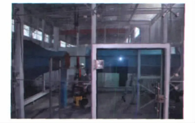
Fig.1 The wind tunnel图1 风洞
1.2 Power system
Multi-phase power system consists of multiphase signal generator,SPWM (Sine Pulse Wave Modulator),multi-phase power amplifier and low frequency high voltage transformers.The voltage in this paper is adopted one phase.The photographs of the power are shown in Fig.2.

Fig.2 The high voltage DC图2 电源内部及面板分布图
1.3 Model and plasma actuator
The airfoil used in this study is a NACA0015.This generic shape is chosen due to its well known steady characteristics.The airfoil has a 100mm chord and a 480mm span.The photograph of the model is shown in Fig.3.
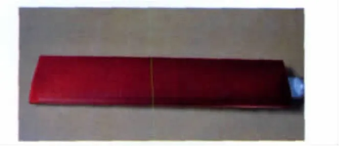
Fig.3 NACA0015airfoil model图3 NACA0015翼型模型
The plasma actuator consists of two electrodes separated by three layers of 0.1mm thick Kapton film.One of the electrodes is made of 0.05mm thick copper foil tape and the other one is the whole airfoil model.The upper electrode is arranged along span wise with a width of 2mm and a length of 440mm.Fig.4shows the illustration of the plasma actuator arrangement.
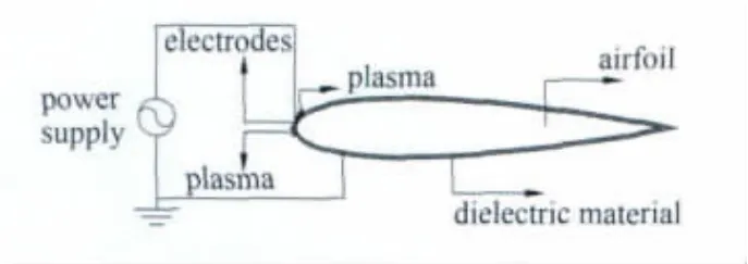
Fig.4 Plasma flow control layout图4 等离子体流动控制布局示意图
The surface of the model is not very smooth and flush when bonded the plasma actuator.Since we only study the basic concept of the flow control effect on the airfoil,it is not necessary to treat the model further more.
1.4 Data acquisition and control system
Data acquisition utilizes data acquisition and control system in the wind tunnel.The system include balance,manostat,data processing software,computer,and angle controller.
The time-averaged lift and drag forces of the airfoil are measured by a five-component strain gauge balance.The range of the angle of attack in this experiment varies from 0to 28deg.
1.5 PIV system
Particle Image Velocimetry(PIV)technology is applied to measure the flow field.The PIV system includes laser system,recording system,synchronizer,smoke generator,data processing software,and computer etc.
2 Results and discussion
The lift coefficients of the airfoil versus angle of attack controlled by the plasma actuator are presented in Fig.5(a).The lift and drag coefficients have not been corrected by accounting for the flow blockage effects.
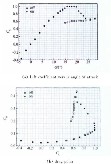
Fig.5 Lift coefficient versus angle of attack and drag polar for the airfoil图5 翼型升力系数和极曲线
The corresponding data of the airfoil without control are also included in the plot.There is no visible lift enhancement on the airfoil at low angles of attack,but significantly lift increment at natural post stall conditions.Without control,the flow separates at an angle of attack of 15deg,which is observed as a sharp decrease in lift and increase in drag.With control,the actuator is able to reattach the flow for angles of attack up to 21deg,which is 6 deg higher than the normal stall angle.The maximum lift coefficient of the airfoil is increased by 11%from 0.90without control to 1.0with control.The control results in an increase in both maximum lift and stall angle.It results in a lift-to-drag ratio improvement of as much as 199%.
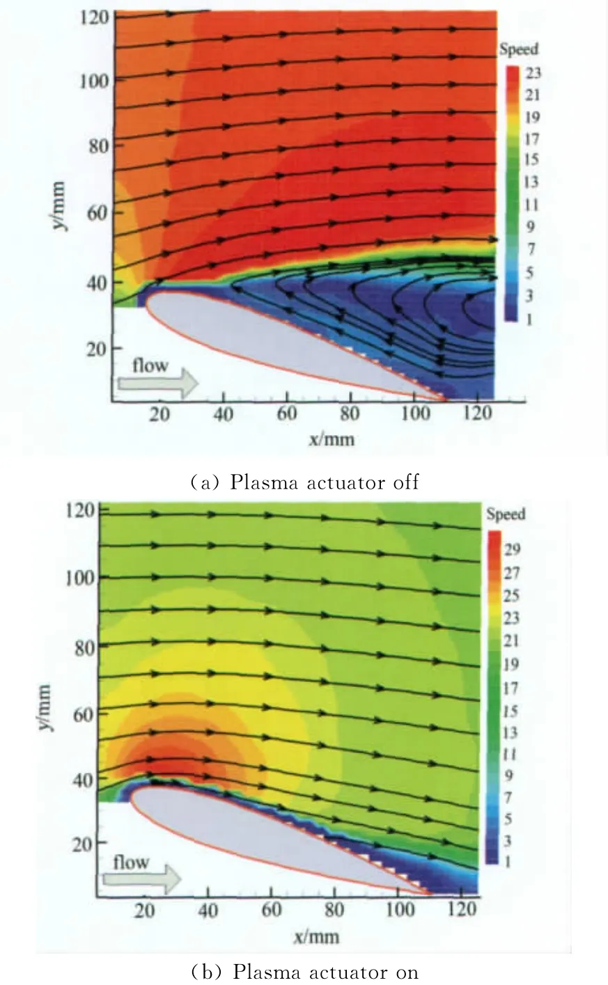
Fig.6 PIV results at angle of attack of 18deg图6 迎角为18°时的PIV测量结果
The results of the PIV show that the drop in lift at large angles of attack is due to separation of the flow at the leading edge.Fig.6(a)shows the flow field of the airfoil at a post stall of 18deg without control.A large separation region covers the whole upper surface of the airfoil.With control,the flow is observed to be attached all over the upper surface,shown in Fig.6(b).The PIV tests are in good agreement with the force measurements.
When the free-stream velocity and the actuator are fixed,the actuator voltage and excitation frequency are the most important factors interested.Firstly,the control effect of actuator voltage was investigated.The lift coefficients at different actuator voltages and fixed excitation frequency of 3.0kHz are shown in Fig.7.Without control,the flow separates at an angle of attack of 15deg.When the actuator voltage is 2.0kV,the flow separates at an angle of attack of 16deg and the stall angle is increased by 1deg.When the actuator voltage is 3.0kV,the flow separates at an angle of attack of 20deg.which is 5 deg higher than the normal stall angle.When the actuator voltage is 4.0kV,the result is more significant that the stall angle delays 6deg.
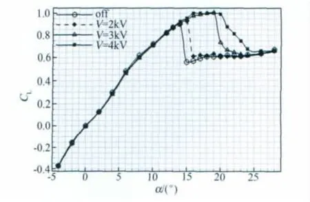
Fig.7 Lift coefficient versus angle of attack for the airfoil at different voltages图7 不同电压下的翼型升力曲线
Further study of the control effect of actuator voltage at a fixed angle was carried out.The results at attack angle of 15~19deg at free-stream velocity of 20m/s and excitation frequency of 3.0kHz are shown in Fig.8.This documents the lift and drag coefficients as a function of the actuator voltage.At attack angle of 15deg,the flow over the airfoil has been naturally separated and the lift coefficient is low and the drag coefficient is high.When the actuator voltage is not high enough,the flow remains separated and there is no improvement in the lift and drag,like the left edge of the plot.However,once a threshold voltage to the actuator is reached,the flow dramatically reattached.This is observed as a large increase in the lift and decrease in the drag,marked by the dashed line in the plot.Above this voltage,there is very little change in the lift and drag coefficients.It is concluded that the actuator voltage has an optimum value and once the actuator voltage is higher than the value,the control is effective.
Fig.8shows that the threshold value is 1.6kV for the attack angles of 15,16and 17deg,while the value is 2.4kV for the angle of 18deg.At higher attack angle the flow separation is much stronger and flow control is more difficult,resulting in higher actuator voltage threshold value.
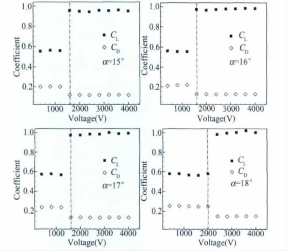
Fig.8 Effect of the actuator voltages on the lift and drag coefficient at different angles of attack图8 不同迎角下电压对升阻力系数的影响
Similar experiments have been done for different excitation frequencies.At a fixed actuator voltage of 4.0kV,the lift coefficients at different frequencies are shown in Fig.9.The stall angle is increased by 5deg at the frequency of 2.0kHz,while the stall angle increased by 6deg at the frequencies of 3.0kHz and 4.0kHz.Moreover,the control effects at the frequencies of 3.0kHz and 4.0kHz have no visible difference.
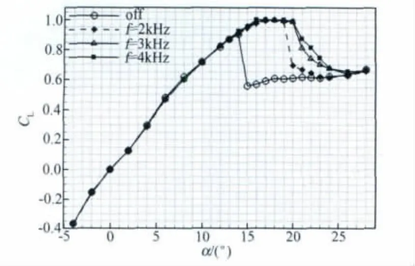
Fig.9 Lift coefficient versus angle of attack for the airfoil at different frequencies图9 不同频率下的翼型升力曲线
The more particular investigation has been done to find an optimum frequency value at different angles.Same as the actuator voltage,different attack angles have different threshold values.As seen in Fig.10,when the actuator voltage is fixed at 4.0kV,the value is 150Hz at angles of 15,16and 17deg.While the value is a sudden break at angle of 18 deg,which is very similar to the actuator voltage and the value is 800Hz.The reason is the same as the actuator voltage.
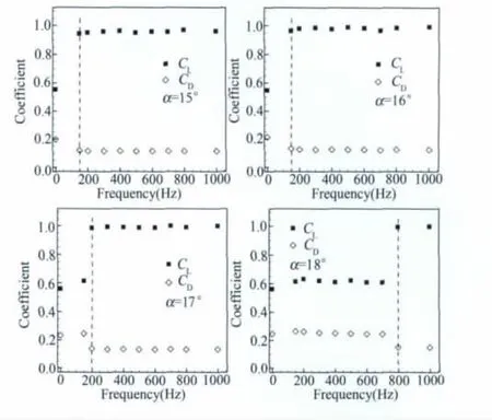
Fig.10 Effect of the excitation frequencies on the lift and drag coefficient at different angles图10 不同迎角下频率对升阻力系数的影响
3 Conclusions
The force measurement and PIV experiments were carried out in the wind tunnel to investigate the influence of plasma actuators on the flow separation control of NACA0015airfoil.The results show that the leading-edge plasma actuators can be effective in controlling the flow separation over the airfoil at low wind speeds.The maximum lift coefficient and stall angle are increased by 11%and 6deg respectively at free-stream velocity of 20m/s.
At a given flow state,there exists threshold values for both the actuator voltage and excitation frequency on the actuators.The threshold values are different with the changing attack angles.At the higher attack angles,the plasma actuator's authority must be increased due to the much stronger flow separation on the airfoil.
[1]CORKE,T C.Design of aircraft[M].New York:Prentice-Hall,2002:38-59.
[2]MCMICAWL J M.Progress and prospects for active flow control using microfabricated electro-mechanical system (MEMS)[R].AIAA 96-0306.
[3]WILTSE J,GLEZER A.Manipulation of free shear flows using piezoelectric actuators[J].J Fluid Mech.,1993,249:261-285.
[4]WARSOP C.AeromemsII:A European research effort to develop MEMS based flow control technologies[R].AIAA Paper 2004-22209,2004.
[5]ROTH J R,SHERMAN D M,WLIKINSON S R.Electrohydrodynamic flow control with a glow-discharge surface plasma[J].AIAA Journal,2000,38(7).
[6]JACOB J,RIVIR R,CAMPBELL C,et al.Boundary layer flow control using AC discharge plasma actuators[R].AIAA 2004-2128.
[7]CORKE T C,JUMPER E J,POST M L,et al.Application of weakly-ionized plasmas as wing flow-control devices[R].AIAA 2002-0350,2002.
[8]POST M L,and CORKE T C.Separation control on high angle of attack airfoil using plasma actuators[J].AIAA Journal,2004,42(11):2177-2184.
[9]CORKE T C,MERTZ B,and PATEL M P.Plasma flow control optimized airfoil[R].AIAA 2006-1208,2006.
[10]PATEL M P,SOWLE Z H,CORKE T C,et al.Autonomous sensing and control of wing stall using a smart plasma slat[R].AIAA 2006-1207,2006.
[11]HE C,CORKE T C,et al.Plasma flaps and slats:an application of weakly ionized plasma actuators [J].Journal of Aircraft,2009,46(3).
[12]ZHANG P F,WANG J J,et al.Experimental study of plasma flow control on highly swept delta wing [J].AIAA Journal,2010,48(1).
[13]HUANG J,CORKE T C,and THOMAS F O.Plasma actuators for separation control of low pressure turbine blades[R].AIAA2003-1027,2003.
[14]HUU P N,et al.Plasma-assisted high lift systems[R].AIAA2009-3943,2009.
[15]YURCHENKOV N and PARAMONOV Yu.Boundary-layer control based on localized plasma generation:wind-tunnel investigations[R].AIAA2010-1007,2010.
Author biography:

WANG Xun-nian(1962-),male,born in Longnan of Jiangxi province,Doctor of Northwestern Polytechnical University.Research field:low speed aerodynamics and experiments in fluid.Address:China Aerodynamics Research &Development Center,Mianyang,Sichuan(621000).Telephone:(0816)2461070,E-mail:xunnian@sohu.com.
1672-9897(2011)04-0009-06
介质阻挡放电等离子体对翼型流动分离控制的实验研究
王勋年1,王万波2,黄 勇2,张 鑫2,黄宗波2
(1.西北工业大学航空学院,西安710072;2.中国空气动力研究与发展中心,四川 绵阳 621000)
在低速开口风洞中进行了等离子体激励器对NACA0015翼型流动分离控制的实验研究。采用PIV技术,对翼型绕流流场进行了测量,显示了施加等离子体激励后流场的变化。通过五分量天平对升力和阻力的测量,研究了激励电压和激励频率对翼型流动分离控制的规律。研究表明,低风速下在翼型前缘施加等离子体激励,能够有效地控制翼型流动分离,在来流为20m/s时,最大升力系数增加11%,失速迎角增加6°;在给定的流动状态下,激励电压和激励频率存在一个阈值,不同迎角下该阈值不同,迎角越大,分离越严重,对激励强度的要求也越高。
等离子体;流动控制;激励器;流动分离
V211.7;O357.4+1
A
date:2010-11-09;Revised date2011-05-08
猜你喜欢
北京航空航天大学学报(2021年6期)2021-07-20
空间科学学报(2021年6期)2021-03-09
空间科学学报(2020年4期)2020-04-22
科学Fans(2019年4期)2019-04-30
北京航空航天大学学报(2017年7期)2017-11-24
北京航空航天大学学报(2017年7期)2017-11-24
北京航空航天大学学报(2017年2期)2017-11-24
北京航空航天大学学报(2016年3期)2016-02-27
科技传播(2014年4期)2014-12-02
少年科学(2014年7期)2014-08-18