悬索桥隧道式锚碇横断面形状对其承载性能影响
2012-08-16 02:24江南,冯君
重庆交通大学学报(自然科学版) 2012年4期
江 南,冯 君
(西南交通大学土木工程学院,四川成都610031)
0 Introduction
Anchorage is the main bearing structure of suspension bridge.The main function of anchorage is transferring the cable force of suspension bridge to the surrounding rock.Gravity anchorage and tunnel anchorage are two commonly used forms of suspension bridges.Gravity anchorage is widely used for it can adapt all kinds of geologic conditions.For example,Akashi-kaikyo Bridge in Japan,the Tsingma Bridge in Hong Kong and Jiangyin Yangtze River Bridge and Toranomon bridge in China all use gravity anchorage.Tunnel anchorage is preferred when nature condition of terrain and geology at the anchorage is better(Lu,2003)[1].For example,tunnel anchorages have been applied in George Washington Bridge,Auckland Bridge,the San Francisco Bay Bridge in America,the Fourth Bridge in Britain and Fengdu Yangtze River Bridge in China,etc..
The bearing capacity of tunnel anchorage depends mostly on geometry dimensions,interface strength between anchorage structure and surrounding rock,and rock strength.Geometry dimensions include cross section type,enlarged angle,and length etc..The results of numerical modeling and model tests show that anchorage inclination,length,enlarged angle,interface roughness have influence on anchorage displacements and its stability(Wang,2005)[2].Many researchers study the failure mechanism and bearing capacity for anchorage with U-type section(Zhu,2005;Zhang,2004)[3-4].The results show that shear failure is main failure mode of surrounding rock,then comes tension-shear failure.The displacements of anchorage are about several millimeters,and the ultimate bearing capacity is larger than seven times of the design cable force.All these studies did not include comparison of the load bearing characteristics for different types of anchorage.
Based on the tunnel anchorage in the Sidu River Bridge in China,we analysis the deformation characteristics,stress characteristics and bearing capacity for U-type and circular section respectively.The results can be useful in optimization of tunnel anchorage in suspension bridge.
1 Cross Section Types of Tunnel Anchorage
Because high requirements for surrounding rock,tunnel anchorage have less applications than gravity anchorage.Literature statistics show that there are thirty-nine suspension bridges built in the 20th,and only seven bridges used tunnel anchorage(Zhu,2005;Zhou,2003)[4-5].According to these project examples,combined with tunnel anchorages built in China in recent years,we summarized the main types of cross section of tunnel anchorage.The results show that the type of cross section of tunnel anchorage can be categorized as U-type and circular type.For example,the George Washington Bridge in America and the Sidu River Bridge in China are U-type tunnel anchorage,and the Fourth Highway Bridge in Britain has circular type tunnel anchorage.Table 1 list cross section types and dimensions used in some tunnel anchorage.

Table 1 Tunnel anchorage datum of suspension bridge at home and abroad表1 国内外部分悬索桥隧道式锚锭资料
2 Numerical Analysis
2.1 Cross Section Type and Boundary Dimensions
Using tunnel anchorage of Sidu River Bridge as prototype,we analyses two kinds of cross section type which are U-type and circular type.For comparison,it is assumed that the front cross section and the back cross section of two types are equal respectively.The area of the two front cross sections are both 98.42 m2,and the area of the two back cross sections are both 175m2,the length of anchorage is 40m.The final cross section size of U-type and circular is showed in Fig.1.
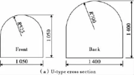
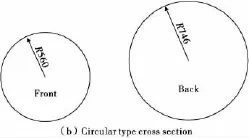
Fig.1 Cross sections sizes of anchorage body(units:cm)图1 锚碇体截面尺寸
The problem of tunnel anchorage of suspension subjected to cable force should be considered as boundless region problem.When finite element method is used,boundary dimensions have obvious influence on the resultaccuracy. Therefore, when determining boundary dimensions,calculation precision and computational cost impact should be taken into account synthetically.Parameter sensitive analysis may be the best method to gain the reasonable boundary dimensions.According to other scholar research,the boundary dimensions are determined as follows.The calculation model has a length of 80m,a height of 140m,and a width of 140m which is about 10 times of the tunnel width.Half of the model is selected to calculate by using symmetry of the model.
2.2 Stress-Strain Behavior and Material Parameters
Rock mass is considered as ideal elastic-plastic material,obeying Mohr-Coulomb yield rule.Anchorage is considered as linear elastic material.The interface between anchorage body and surrounding rock is modeled by interface element of which friction behavior obey Mohr-Coulomb yield rule.The interfaces allow open and slippage relatively.
A extended Mohr-Coulomb model is adopted for the rockmass(Hibbit K,2010)[6].The expression of yield function is as follows,
Menétrey-Willam plasticity potential function(Menétrey,1995)[7]and orthogonal flow rule are used,and material hardening is not taken into account.
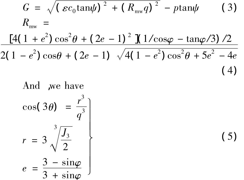
Where:φ is the internal friction angle;ψ is the dilation angle;p is the equivalent pressure stress;q is the Mises equivalent stress;J3is the third stress partial derivative invariant;θ is the deviatoric polar angle;c0is the initial cohesion yield stress;ε is a parameter,referred to as the meridional eccentricity.
The material parameters of rockmass,anchorage body and interface are listed in Table 2.

Table 2 Material parameters表2 材料参数
2.3 Load Case
Taking no account of dead load stress caused by surrounding rock and anchorage,only the design cable tensile force of 220MN is considered in this analysis.Treating cable tensile force as equivalent uniform compressive stress at the rear face of anchorage,which is σ =220,000/175=1,257kPa.The load cases include applying one time of cable force,two times of cable force,three times of cable force till arriving at the ultimate bearing capacity of the anchorage,when the failure of the anchorage and/or the surrounding rock would occur.
2.4 Element Mesh and Boundary Condition
Meshing the anchorage structure and rock mass into 8-node hexahedral element(C3D8R),and increasing element density at anchorage area to improve calculation precision.There are 15,753 hexahedral elements and 17,712 nodes for U-type cross section model(see Fig.2).The boundary conditions are that four peripheral boundary faces around the tunnel anchorage have normal constraint;the bottom face is fixed in all three directions,and the top face is free.
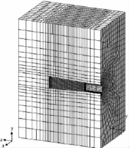
Fig.2 Finite element mesh of U-type图2 U型截面隧道锚网格划分
2.5 Results Analysis
2.5.1 Displacement Analysis
The results show that the displacement direction of anchorage is mainly axial due to various cable forces.When bearing one time of cable force(1,257kPa),contour of the anchorage total displacement is showed in Fig.3.

Fig.3 Displacement distribution of anchorage图3 一倍缆力作用下隧道锚位移分布
According to Fig.3,the biggest displacements both appear at the rear face of the anchorage.U-type is 1.348mm and circular type is 1.044mm.The displacement of circular tunnel anchorage is less than U-type tunnel anchorage by 22%.For U-type cross section,the displacement distribution is uneven,and the displacement at the lower part is bigger than the upper part at the rear face.The displacements of circular type distribute symmetrically around the axis of anchor.Therefore,application of circular type cross section can decrease the displacement obviously than the U-type cross section.
2.5.2 Stress Analysis
In order to observe the stress state of wall rock,setting path at the perimeter of anchorage cave(showed in Fig.4).
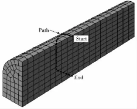
Fig.4 Path around the anchorage cave图4 环绕洞周路径布置示意
According to the stress value subjected to one time of cable force(S1 is the maximum principal stress,S3 is the minimum principal stress,tensile is positive),plot diagram showed in Fig.5,which shows surrounding rock mainly bear compressive stress.
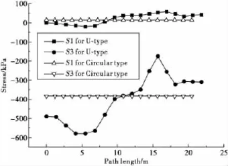
Fig.5 Principal stresses distribution图5 主应力沿环绕洞周路径的分布
Stresses of U-type cave change comparatively bigger,and the maximum compressive stress located at the top zone of arch,which is 578kPa,while at the sidewall and the bottom is smaller.Stresses of circular type anchor cave are uniform around the perimeter,and the maximum compressive stress is 383kPa.In addition,some tensile stresses occur around the anchor cave.U-type cross section is uneven,and the biggest tensile stress is 57kPa;circular type cross section is uniform,and the biggest tensile stress is only 14kPa.So circular cross section can decreases stress concentration obviously,which is helpful to improve the bearing capacity of surrounding rock.
2.5.3 Analysis of Ultimate Bearing Capacity
Because the main function of anchorage is bearing the cable tensile force of suspension bridge,over-load-ing method is adapted to gain ultimate bearing capacity.That is to say,in the analysis,we continually increase the load of cable force(one time,two times,etc.)till the calculation can’t reach convergence.Then we determine the bearing capacity by considering the load-displacement diagram.The relationship between the biggest displacement of anchorage and the load is showed in Fig.6.
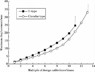
Fig.6 The maximal displacement vs.load curves图6 锚碇体最大位移与荷载的关系
It can be seen from Fig.6 that,as for U-type anchorage,displacement increases linearly with cable force increasing from one time to five times,then it change rapidly that means the surrounding rock start to reach plastic phase.When the load is 11 times of design cable force,the calculation can’t convergent.So the ultimate bearing capacity of the U-type anchorage is 11 times of the design cable force.The displacement of circular anchorage increase linearly with cable force increasing from one time to six times,then displacement change rapidly,after 13 times of cable force,the calculation can’t convergent.It means that the ultimate bearing capacity of the circular type anchorage is 13 times of design cable force.So the ultimate load of circular type cross section increase by 18%compared with the U-type cross section.
3 Conclusions
1)Tunnel anchorage is one kind of main type of anchorage used in suspension bridge,it is preferred when nature condition of terrain and geology is better.Investigation of some suspension bridges at home and abroad indicates that the cross section shape of tunnel anchorage can be divided into two categories:U-type and circular type.
2)Under the effect of an identical cable force(220MN),the maximum displacement of both cross sections appears at the rear face of anchorage.For U-type crosssection the maximum displacementis 1.348mm,for circular type it is 1.044mm,which decrease by 22%compared with U-type.
3)Stresses distribution around the U-type anchorage cave are not uniform.Compressive stress at the portion of arch is much bigger than the portion of side wall and bottom floor,and the maximum compressive stress is 578kPa.As for circular anchorage cave,the stress distributes uniformly around the tunnel.The maximum compressive stress is 383kPa.So circular cross section can decrease stress concentration obviously,that may be helpful to increase the bearing capacity of surrounding rock.
4)The ultimate bearing capacity of U-type anchorage is 11 times of the design cable force,while that of circular type anchorage is 13 times of the design cable force.The ultimate bearing capacity of circular type increase by 18%compared with U-type anchorage.
[1]Lu Yongcheng.The east tunnel-anchor of Chongqing Egongyan Yangtze River Bridge[J].China City Engineering,2003(6):31-34.卢永成.重庆鹅公岩长江大桥东隧道式锚碇[J].中国市政工程,2003(6):31-34.
[2]Wang Haibin,Gao Bo,Sun Zhen.Study on mechanical behavior of tunnel anchorage system for suspension bridge[J].Chinese Journal of Rock Mechanics and Engineering,2005,24(15):2728-2735.汪海滨,高波,孙振.悬索桥隧道式锚碇系统力学行为研究[J].岩石力学与工程学报,2005,24(15):2728-2735.
[3]Zhang Lijie,Huang zhengjia,Ding Xiuli.Numerical analysis with FLAC3D of a tunnel anchorage of Sidu River Bridge[J].Chinese Journal of Rock Mechanics and Engineering,2004,23(supp2):4971-4974.张利洁,黄正加,丁秀丽.四渡河特大桥隧道锚碇三维弹塑性数值分析[J].岩石力学与工程学报,2004,23(增刊2):4971-4974.
[4]Zhu Yu,Wei Jun,Li Hao,et al.Analysis of displacements of tunnel-type anchorage for a large-span suspension bridge[J].Chinese Journal of Rock Mechanics and Engineering,2005,24(19):3588-3593.朱玉,卫军,李昊,等.大跨径悬索桥隧道锚变位分析[J].岩石力学与工程学报,2005,24(19):3588-3593.
[5]Zhou Mengbo.Manual of Suspension Bridges[M].Beijing:China Communications Press,2003:105-219.
[6]Hibbit K,Sorensen Inc.ABAQUS Theory Manual:Ver.6.10[M/OL].2010[2012-3-20].http://www.simulia.com
[7]Menétrey P,William K J.Tri-axial failure criterion for concrete and its generalization [J].ACI Structural Journal,1995(92):311-318.
猜你喜欢
数学物理学报(2022年4期)2022-08-22
水利水运工程学报(2022年3期)2022-07-07
疯狂英语·新读写(2022年12期)2022-03-07
中国交通信息化(2021年9期)2021-11-22
美与时代·美术学刊(2021年3期)2021-05-28
生物医学工程学进展(2021年1期)2021-04-15
照明工程学报(2019年3期)2019-07-09
中国公路(2017年11期)2017-07-31
中国生物医学工程学报(2017年6期)2017-02-10
城市道桥与防洪(2014年5期)2014-02-27