
基于TiO2纳米管阵列的高效正面透光型染料敏化太阳能电池的制备及其光电性能
2014-10-18 05:27高素雯吴晚霞阙兰芳吴季怀林建明黄妙良
物理化学学报 2014年3期
高素雯 兰 章,2,3,* 吴晚霞 阙兰芳 吴季怀,2,3 林建明,2,3 黄妙良,2,3
(1华侨大学材料科学与工程学院,福建厦门 361021;2环境友好功能材料教育部工程中心,福建厦门 361021;3福建省高等教育功能材料重点实验室,福建厦门 361021)
1 Introduction
Dye-sensitized solar cells(DSSCs)have been a researching focus among new types of solar cells since O′Regan and Grätzel first reported.1Compared with conventional silicon solar cells,DSSCs have an absolute advantage of low-cost and easy preparation.2,3Generally,the DSSC is composed of a dyesensitized photoanode,an electrolyte typically containing the iodine/iodide redox couple,and a counter electrode.4The photoanode is usually composed of TiO2nanoparticles(TNPs).5However,the TNPs based photoanodes have some drawbacks affecting the photovoltaic performance of DSSCs.For example,the existed random networks and large interfaces will result in serious charge recombination between electrons and iodide ions in the electrolyte;numerous boundaries among TNPs will trap electrons and induce short electron diffusion length.6To solve the problems,researchers have attempted to synthesize and utilize some ordered one-dimensional TiO2nanorods,7nanowires,8and nanotubes in DSSCs.9
As a promising alternative to traditional TNPs based photoanodes in DSSCs,TiO2nanotubes(TNTs)have been attracting intensive interests.10Highly ordered,one-dimensional TNTs have been widely used in DSSCs,sensors,photocatalysis and water splitting.11-13Applied in DSSCs,TNTs have some outstanding properties.For one hand,one-dimensional TNTs can provide a vertical electron transport path which can effectively reduce charge recombination;for another hand,the less grain boundaries lead to higher electron mobility and faster electron transport speed compared with the TNPs based photoanodes.14However,mainly due to low surface area,the photovoltaic performance of TNTs based DSSCs is still much lower than that of the TNPs based DSSCs.One efficient way to increase the surface area of TNT membranes and further increase the photovoltaic performance of DSSCs is to form secondary or hierarchical structure.15,16However,the as-formed particle-connected secondary structure in the TNT membranes will partly destroy the fast ordered electron transport channels.Here,some improvements are carried out to fabricate highly photovoltaic performance of TNTs based DSSCs through maintaining the fast ordered electron transport channels in the TNT membranes and increasing surface roughness for enhancing dye loading amounts at the same time.
2 Experimental
2.1 Materials
All solvents and reagents were of AR grade quality and were used as received.2-propanol,concentrated nitric acid(65%(w)aqueous solution),ethanol,ethylene glycol,ammonium fluoride,hydrofluoric acid,H2O2(30%(w)aqueous solution),tetra-n-butyl titanate,acetic acid,acetonitrile,titanium tetrachloride,tetrabutyl ammonium iodide,4-tert-butyl pyridine,sodium iodide,iodine,and H2PtCl6·6H2O were purchased from Sinopharm Chemical Reagent Co.Ltd.,China.Ti-foils(0.2 mm thick,99%(w)purity)were purchased from Baoji Yunjie Metal Production Co.Ltd.Conductive glasses FTO glasses(fluorine doped tin oxide over-layer,sheet resistance 15 Ω·□-1)were purchased from Nippon Sheet Glass Co.JP.N719 dye(Ru[LL'-(NCS)2],L=2,2'-bipyridyl-4,4'-dicarboxylic acid,L'=2,2'-bipyridyl-4,4'-ditetrabutylammonium carboxylate)from Dye sol.
2.2 Preparation of TiO2nanotube membranes
Ti foils(2 cm×3 cm)were treated with ultrasonic cleanser in deionized water,2-propanol,and ethanol for 5 min,respectively,and then rinsed with ethanol and dried at room temperature.The cleaned Ti foils were polished in a solution containing H2O(50%(volume fraction)),concentrated nitric acid(50%(volume fraction)),and NH4F(1.7%(w)vs the total weight of H2O and concentrated nitric acid).The polished Ti foils were subjected to a two-step anodization in electrolyte containing ethylene glycol,H2O(0.5%(volume fraction)vs ethylene glycol),and ammonium fluoride(0.25%(w)vs ethylene glycol)at room temperature.Namely,the polished Ti foils were firstly anodized at 60 V for 4 h.After thermally treated at 250°C for 2 h and cooled down to room temperature,they were anodized again at 60 V for 5 min.After two-step anodization,the Ti foils were rinsed with ethanol,dried at room temperature,and then immersed into H2O230%(w)aqueous solution for 1 h to detach the TNT membranes.
2.3 Preparation of photoanodes and assembling of front-side illuminated dye-sensitized solar cells
The detached TNT membranes about 12.5 μm were incised into several pieces with area of 0.1 cm2(0.25 cm×0.4 cm)and adhered to FTO glasses using the paste containing 10-20 nm anatase TiO2nanoparticles prepared with the same method reported in the reference.17The thickness of the TiO2adhesive under-layer was about 1 μm.After sintered at 450 °C for 30 min,the TNT photoanodes were further treated with HF,TiCl4,and HF combining with TiCl4.The details are as follows.HF treatment:the TNT photoanodes were dipped in 0.35%(volume fraction)HF aqueous solution at room temperature for 1 h,and then sintered again at 450°C for 30 min.TiCl4treatment:the TNT photoanodes were dipped in 0.05 mol·L-1TiCl4aqueous solution at 90 °C for 30 min,and then sintered again at 450 °C for 30 min.HF combining with TiCl4treatments:the TNT photoanodes were treated with HF solution and TiCl4solution with the methods as above mentioned in sequence.The as-prepared TNT photoanodes were sensitized in 0.25 mmol·L-1anhydrous ethanol solution of N719 dye for 24 h at room temperature.The sensitized TNT photoanodes were rinsed with anhydrous ethanol and dried in air.Pt counter electrode was prepared with the same method reported in the reference.18The DSSC was assembled as follows.Firstly,a drop of electrolyte was dripped into the sensitized TNT photoanode,and then a piece of Pt counter electrode was placed above the photoanode.Secondly,the two electrodes were clipped together and a cyanoacrylate adhesive was used as sealant to seal the cell.Bisphenol A epoxy resin was used in a further sealing process.The liquid electrolyte contained 0.4 mol·L-1sodium iodide,0.1 mol·L-1tetrabutyl ammonium iodide,0.5 mol·L-14-tert-butylpyridine,and 0.05 mol·L-1iodine in acetonitrile solution.
2.4 Measurements
The surface morphologies and thickness of TNT membranes were characterized by a field emission scanning electron microscopy(FESEM,S-4800,HITACHI,Japan).X-ray diffraction(XRD)measurements were carried out with a Bruker D8 ADVANCE(Germany),using Cu Kα1radiation(λ=0.15418 nm).A UV-Vis 2550 spectrophotometer(Shimadzu,Japan)was employed to measure UV-Vis absorption and reflectance spectra.Electrochemical impedance spectroscopy(EIS)measurements were performed using a CHI 660 C electrochemical workstation(CH Instrument Inc.,USA).The impedance spectra were analyzed by an equivalent circuit model interpreting the characteristics of DSSCs with Zview software.19Photovoltaic tests were carried out by measuring photocurrent-voltage(I-V)characteristic curves under simulated AM 1.5G solar illumination at 100 mW·cm-2from a xenon arc lamp(CHFXM500,Trusttech Co.,Ltd,China)in ambient atmosphere and recorded with a CHI 660 C electrochemical workstation.All of the samples were measured three times and the average data were taken.Incident-photon-to-current conversion efficiency(IPCE)curves were measured as a function of wavelength from 300 to 800 nm using the Newport IPCE system(Newport,USA).
3 Results and discussion
Fig.1 shows X-ray diffraction patterns of TNT membranes treated with HF and TiCl4solutions,respectively,and the original non-treated sample after sintered at 450°C for 30 min.The standard 2θcharacteristic peaks of anatase TiO2according to the JCPDS#21-1272 are at 25.3°,37.55°,47.85°,53.75°,55.05°,and 62.35°,which are all existed in the three samples,so the crystal structures of the samples are all anatase.20The diffraction intensity of HF solution treated sample is stronger than the other two samples,so its crystallinity is higher than the others.
Fig.2 shows SEM images of top and cross-sectional views of TNT membranes without and with HF,TiCl4,and HF combining with TiCl4treatments.It is seen that the non-treated TNT membrane is composed with highly ordered TNT array with smooth surfaces.After HF treatment,the top ends of former individual TNTs are connected together to form a thin porous layer on up-side of the membrane;and the original structure of ordered TNT walls does not obviously change except for a little rougher.However,after TiCl4or HF combining with TiCl4treatments the morphologies of TNT membranes are changed significantly compared with that of the non-treated TNT membrane.Firstly,the porous top-side morphology disappears and is substituted by a compact layer composed with nanoparticles.Secondly,there appear many nanoparticles both on the inner and outer surfaces of TNT walls.Comparing Fig.2(e,f)and Fig.2(g,h),one can see that the nanoparticles on the top-side of the membrane in HF combining with TiCl4treated sample are bigger than the others.
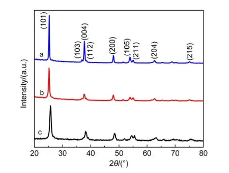
Fig.1 X-ray diffraction patterns of TNT membranes after sintered at 450°C for 30 min

Fig.2 SEM images of top and cross-sectional views of TNT membranes
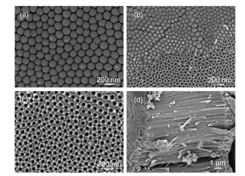
Fig.3 SEM images of back-side views of TNT membranes
Fig.3 shows SEM images of back-side view of TNT membranes as prepared and corroded by 30%(w)H2O2aqueous solution and the cross-sectional image of TNT photoanode.One can observe that the back-side of TNT membrane is composed with ordered close-end semisphere-like TNT layer by the secondary anodization.Due to the miss of thermal treatment,the formed secondary TNT layer can be easily corroded by H2O2reagent.21From Fig.3(b,c),we can see that the thin TNTs under layer disappear after H2O2corrosion;and the newly formed under layer is porous,which is beneficial for strongly adhered to FTO glasses with TiO2nanoparticle paste.Moreover,the through structure as shown in Fig.3(d)can provide a direct electron transport channel to FTO glasses by omitting the closeend under layer in the membrane,and improve the penetrability of electrolyte in the photoanode.22
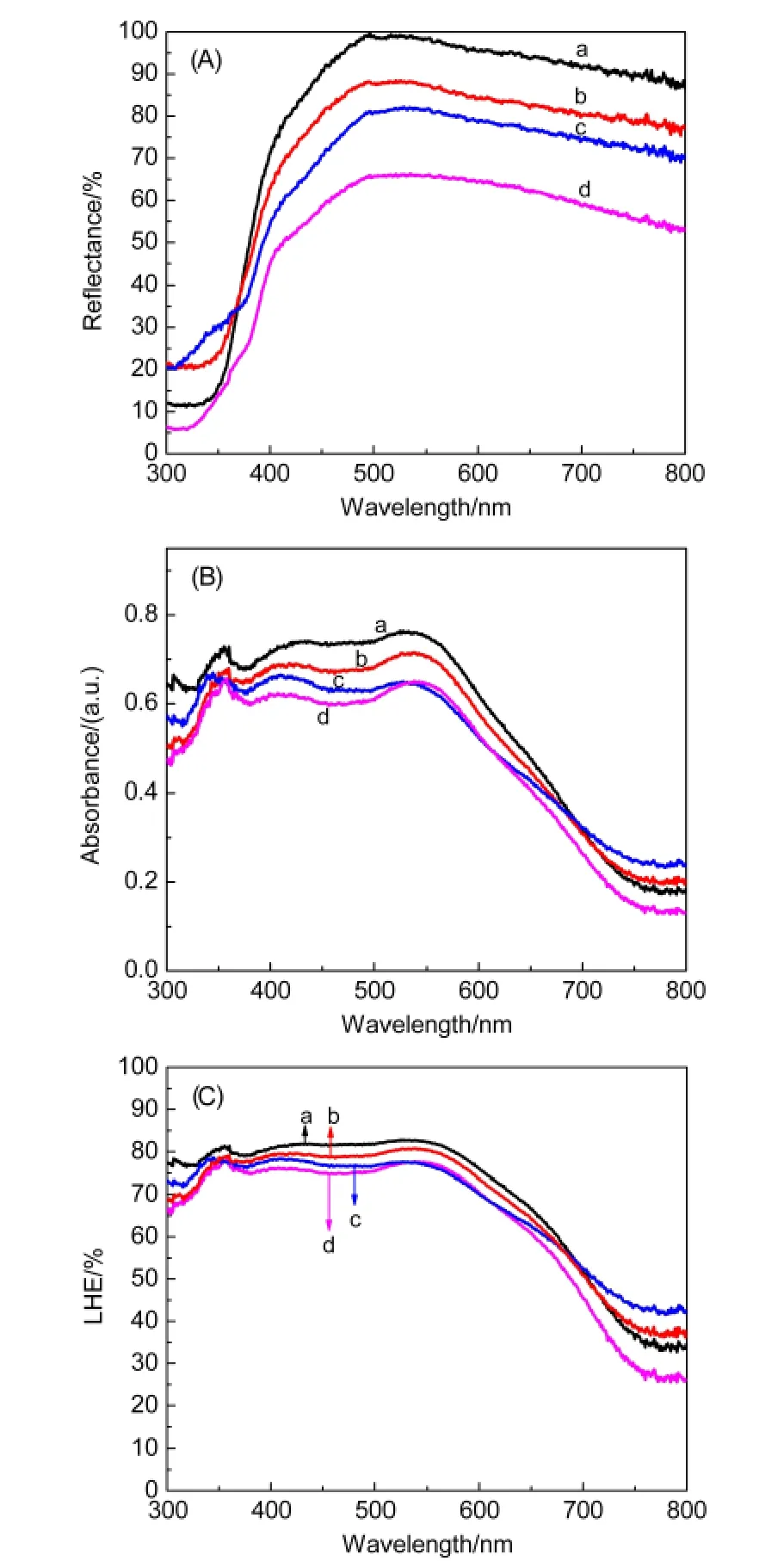
Fig.4 UV-Vis diffused reflectance spectra of TNT membranes(A);absorption(B)and LHE(C)spectra of TNT photoanodes
Fig.4(A,B)shows the UV-Vis diffused reflectance spectra of TNT membranes and absorption spectra of TNT photoanodes.The light scattering ability of the TNT membranes is improved obviously after HF and TiCl4treatments as shown in Fig.4(A).The changed top-side morphologies and the increased rough-ness of the TNT walls as discussed above mainly response for the changed diffused reflectance of the TNT membranes.From Fig.4(B),it is seen that the treated samples all show enhanced light absorbance compared with the non-treated one.The increased roughness of TNTs can increase dye-loading amounts(as listed in Table 1),resulting in the enhanced light absorbance in the short-wavelength region(300-570 nm);and the increased light scattering ability of the TNT membranes is mainly responsible for the enhanced light absorbance in the longwavelength region(570-800 nm).23The light harvesting efficiency(LHE)[LHE(λ)=1-10-ABS(λ),where ABS(λ)is absorbance of the photoanodes of the samples]shown in Fig.4(C)can reflect the effects of the treatments more directly.24
Photovoltaic performance of DSSCs based on TNT photoanodes with different treatments is presented in Fig.5,and the corresponding parameters:short-circuit current density(Jsc),open-circuit voltage(Voc),fill factor(FF),and power conversion efficiency(PCE)are listed in Table 1.We can see that the values of Jscof DSSCs with the treated photoanodes are all improved compared with the original non-treated one;and the TiCl4treatment shows higher efficiency in enhancing Jscthan that of HF treatment.Moreover,by HF combining with TiCl4treatments,Jscof the DSSC can further attain to a higher value.As aforementioned,the increased dye-loading amounts and light harvesting efficiency are the main reasons for the enhanced Jsc,which can be verified by measuring the IPCE performance of the DSSCs.
As shown in Fig.6(A),one can observe that the DSSCs with the treated photoanodes show enhanced IPCE;and the change tendencies are consistent with that of Jsc.The absorbed-photonto-current conversion efficiency(APCE),which is derived from the IPCE and LHE[APCE(%)=IPCE(%)/LHE(%)],24,25is also shown in Fig.6(B)to more directly demonstrate the im-proved photon-to-electron conversion ability of DSSCs with the treated photoanodes.From the data,it is seen that TiCl4treatment can efficiently enhance the APCE of the DSSC in all wavelength region;and by combining with HF treatment,a higher APCE is obtained.The TiCl4and HF combining with TiCl4treated samples have maximum APCE about 84.90%at 510 nm and 89.55%at 530 nm,respectively.Moreover,the two samples also show high APCE(exceeding 20%)in the near-infrared long-wavelength region(700-770 nm).However,the DSSC with non-treated one shows a lower APCE(below 10%)in the same wavelength region.
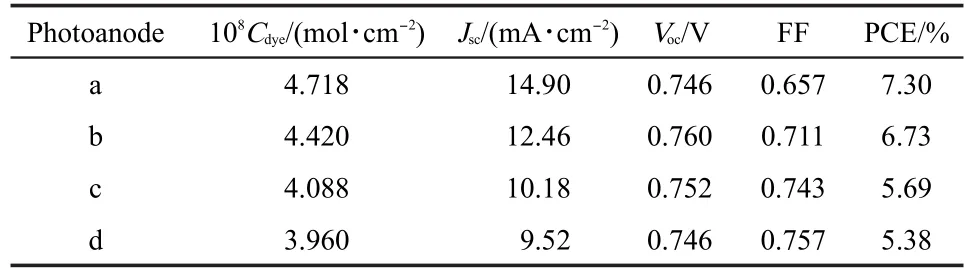
Table 1 Photovoltaic parameters of DSSCs as shown in Fig.5

Fig.5 Photocurrent density-voltage curves of DSSCs based on TNT photoanodes
From the photovoltaic parameters of the DSSCs presented in Table 1,it is found that the changes of Vocare small;whereas the values of FF are decreased obviously after treatments.The reason may be owing to the increased density of the TNT membranes by fitting the new generated TiO2nanoparticles,which results in hindering the deep penetration of electrolyte into TNTs and enhancing the resistance of the DSSCs.Even so,owing to the largely enhanced Jsc,the PCE of the DSSCs with the treated photoanodes is still improved.The best PCE of the DSSCs can attain to 7.30%by HF combining with TiCl4treatments,with 35.69%enhancement compared with the non-treated DSSC(5.38%).

Fig.6 IPCE(A)and APCE(B)spectra of DSSCs based on TNT photoanodes
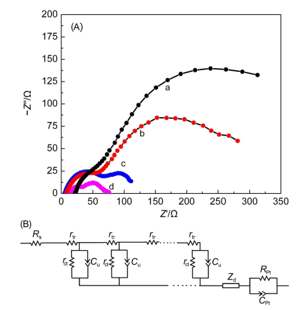
Fig.7 Nyquist plots of DSSCs based on TNT photoanodes at 0.6 V applied forward bias under dark condition(A)and the equivalent circuit model(B)
The EIS measurements are carried out to deeply detect the electron transport and kinetic properties in the DSSCs with non-treated and treated TNT photoanodes as shown in Fig.7(A).A transmission line model(Fig.7(B))is used to describe the kinetic processes of the DSSCs.The corresponding parameters:charge transport resistance Rtr(Rtr=rtrL),interfacial charge recombination resistance Rr(Rr=rct/L),distributed chemical capacitance Cu(Cu=cuL),electron lifetime τn(τn=RrCu),effective electron diffusion length Ln[Ln=L(Rr/Rtr)0.5],and collection efficiency ηcol=Rr/(Rr+Rtr)are summarized in Table 2(where L is the thickness of the TNT membrane).26
From the data,one can observe that HF treatment can suppress the recombination reaction efficiently(due to the obviously increased Rrcompared with the non-treated one),so the ηcoland Lnincrease,resulting in the improved photovoltaic performance of the DSSC.For TiCl4treatment,the value of Rris increased greatly.Owing to the increased value of Rtrat the same time,the enhancements of ηcoland Lnare little lower than that of HF treated sample,whereas they are still higher thanthat of the non-treated one,so the DSSC can generate high Jscby combining with the largely increasedτn.Using HF combining with TiCl4treatments,the values of EIS key parameters such as Rr,ηcol,Ln,and τnare all further enhanced,so the PCE of the DSSC can attain to a higher value.It also can be seen that the TiCl4and HF combining with TiCl4treated samples show higher Rtrthan that of the non-treated one,which may result in lower values of FF.The values of Cu,reflecting the surface area variation,are increased in the DSSCs with treated TNT photoanodes,which is consistent with the increased roughness of the TNTs.
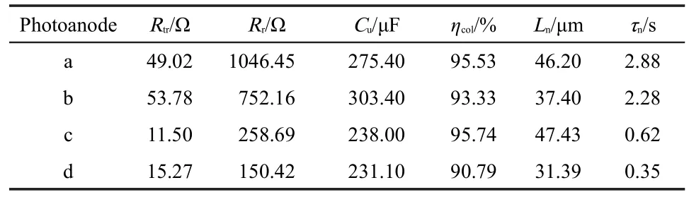
Table 2 Parameters determined by fitting the EIS experimental data to the equivalent circuit shown in Fig.7
4 Conclusions
High efficiency front-side illuminated dye-sensitized solar cells based on ordered TNTs have been successfully prepared.It is found that the high temperature sintering process can avoid damage of the ordered TNTs by HF treatment and maintain the fast electron transport channels in the membranes.Following with HF,TiCl4,and HF combining with TiCl4treatments,the TNTs become rougher,resulting in the increased dye loading amounts,light scattering ability,and light harvesting efficiency,which are all beneficial for improving the IPCE of DSSCs.The EIS analysis reveals that some key parameters describing the kinetic processes of DSSCs are made better after the HF or TiCl4treatment,especially the sample treated with HF combining with TiCl4,which can attain to the highest power conversion efficiency about 7.30%,with 35.69%enhancement compared with the non-treated DSSC(5.38%).
(2)Bella,F.;Bongiovanni,R.;Kumar,R.S.;Kulandainathan,M.A.;Stephanc,A.M.J.Mater.Chem.A 2013,1,9033.doi:10.1039/c3ta12135f
(3)Xin,X.;He,M.;Han,W.;Jung,J.;Lin,Z.Angew.Chem.Int.Edit.2011,50,11739.doi:10.1002/anie.201104786
(4)Grätzel,M.Nature 2001,414,338.doi:10.1038/35104607
(5)Shu,W.;Liu,Y.;Peng,Z.;Chen,K.;Zhang,C.;Chen,W.J.Alloy.Compd.2013,563,229.doi:10.1016/j.jallcom.2013.02.086
(6)Frank,J.;Kopidakis,N.;Lagemaat,J.Coord.Chem.Rev.2004,248,1165.doi:10.1016/j.ccr.2004.03.015
(7)(a)Liu,R.H.;Zhang,S.;Xia,X.Y.;Yun,D.Q.;Bian,Z.Q.;Zhao,Y.L.Acta Phys.-Chim.Sin.2011,27,1701.[刘润花,张 森,夏新元,云大钦,卞祖强,赵永亮.物理化学学报,2011,27,1701.]doi:10.3866/PKU.WHXB20110734(b)Lan,Z.;Wu,J.H.;Lin,J.M.;Huang,M.L.J.Inorg.Mater.2011,26,119.[兰 章,吴季怀,林建明,黄妙良.无机材料学报,2011,26,119.]
(8)(a)Xiao,Y.M.;Wu,J.H.;Yue,G.T.;Lin,J.M.;Huang,M.L.;Fan,L.Q.;Lan,Z.Acta Phys.-Chim.Sin.2012,28,578.[肖尧明,吴季怀,岳根田,林建明,黄妙良,范乐庆,兰 章.物理化学学报,2012,28,578.]doi:10.3866/PKU.WHXB201201032(b)Feng,X.;Shankar,K.;Varghese,O.K.;Paulose,M.T.;Latempa,J.;Grimes,C.A.Nano Lett.2008,8,3781.
(9)(a)Zhang,Z.Y.;Sang,L.X.;Sun,B.;Zhang,X.M.;Ma,C.F.Acta Phys.-Chim.Sin.2010,26,2935. [张知宇,桑丽霞,孙 彪,张晓敏,马重芳.物理化学学报,2010,26,2935.]doi:10.3866/PKU.WHXB20101131(b)Hyeokapark,J.;Guakang,M.Chem.Commun.2008,2867.
(10)(a)Li,H.H.;Chen,R.F.;Ma,Z.;Zhang,S.L.;An,Z.F.;Huang,W.Acta Phys.-Chim.Sin.2011,27,1017.[李欢欢,陈润锋,马 琮,张胜兰,安众福,黄 维.物理化学学报,2011,27,1017.]doi:10.3866/PKU.WHXB20110514(b)Mor,G.K.;Shankar,K.;Paulose,M.;Varghese,O.K.;Grimes,G.A.Nano Lett.2006,6,215.
(11)Jun,Y.;Park,J.H.;Kang,M.G.Chem.Commun.2012,48,6456.doi:10.1039/c2cc30733b
(12)(a)Su,Y.L.;Li,Y.;Du,Y.X.;Lei,L.C.Acta Phys.-Chim.Sin.2011,27,939.[苏雅玲,李 轶,杜瑛珣,雷乐成.物理化学学报,2011,27,939.]doi:10.3866/PKU.WHXB20110401(b)Chang,W.T.;Hsueh,Y.C.;Huang,S.H.;Liu,K.I.;Kei,C.C.;Perng,T.P.J.Mater.Chem.A 2013,1,1987.
(13)Zhang,Z.;Wang,P.Energy Environ.Sci.2012,5,6506.doi:10.1039/c2ee03461a
(14)Kuang,D.;Brillet,J.;Chen,P.;Takata,M.;Uchida,S.;Miura,H.;Sumioka,K.;Zakeeruddin,S.M.;Grätzel,M.ACS Nano 2008,2,1113.doi:10.1021/nn800174y
(15)Zhang,T.;Hu,X.;Fang,M.;Zhang,L.;Wang,Z.CrystEngComm 2012,14,7656.doi:10.1039/c2ce25323b
(16)Tao,L.;Xiong,Y.;Liu,H.;Shen,W.J.Mater.Chem.2012,22,7863.doi:10.1039/c2jm00005a
(17)Lan,Z.;Wu,J.H.;Lin,J.M.;Huang,M.L.J.Mater.Chem.2011,21,15552.doi:10.1039/c1jm12812d
(18)Lan,Z.;Wu,J.H.;Lin,J.M.;Huang,M.L.J.Mater.Chem.2012,22,3948.doi:10.1039/c2jm15019k
(19)Wang,Q.;Moser,J.E.;Grätzel,M.J.Phys.Chem.B 2005,109,14945.doi:10.1021/jp052768h
(20)Lan,Z.;Wu,J.H.;Lin,J.M.;Huang,M.L.J.Mater.Sci.:Mater.Electron.2010,21,833.doi:10.1007/s10854-009-0003-4
(21)Choi,J.;Park,S.H.;Kwon,Y.S.;Lim,J.;Song,I.Y.;Park,T.Chem.Commun.2012,48,8748.doi:10.1039/c2cc33629d
(22)Yip,C.T.;Guo,M.;Huang,H.;Zhou,L.;Wang,Y.;Huang,C.Nanoscale 2012,4,448.doi:10.1039/c2nr11317a
(23)Huang,F.;Chen,D.;Zhang,X.L.;Caruso,R.A.;Cheng,Y.B.Adv.Funct.Mater.2010,20,1301.doi:10.1002/adfm.v20:8
(24)Yanagida,M.;Yamaguchi,T.;Kurashige,M.;Hara,K.;Katoh,R.;Sugihara,H.;Arakawa,H.Inorg.Chem.2003,42,7921.doi:10.1021/ic034674x
(25)Wang,Z.S.;Li,F.Y.;Huang,C.H.J.Phys.Chem.B 2001,105,9210.doi:10.1021/jp010667n
(26)Bisquert,J.;Belmonte,G.G.;Santiago,F.F.;Ferriols,N.S.;Bogdanoff,P.;Pereira,E.C.J.Phys.Chem.B 2000,104,2287.doi:10.1021/jp993148h
猜你喜欢
世界科学技术-中医药现代化(2022年2期)2022-05-25
世界科学技术-中医药现代化(2021年8期)2021-12-21
世界科学技术-中医药现代化(2021年7期)2021-11-04
陶瓷学报(2019年5期)2019-01-12
物理化学学报(2018年6期)2018-03-08
分析化学(2018年12期)2018-01-22
中国塑料(2016年8期)2016-06-27
中国塑料(2016年12期)2016-06-15
物理化学学报(2015年5期)2015-02-28
应用化工(2014年11期)2014-08-16
