
Instantaneous rotation speed measurement and error analysis for variable speed hydraulic system
2015-03-29 07:58YANGBinGULichenLIUYongWANGPing
YANG Bin, GU Li-chen,2, LIU Yong,3, WANG Ping
(1. National Engineering Laboratory for Highway Maintenance Equipment, Chang’an University, Xi’an 710064, China;2. School of Mechanical and Electronic Engineering, Xi’an University of Architecture and Technology, Xi’an 710054, China;3. School of Mechanical Engineering, Hubei University of Automotive Industries, Shiyan 442002, China)
Instantaneous rotation speed measurement and error analysis for variable speed hydraulic system
YANG Bin1, GU Li-chen1,2, LIU Yong1,3, WANG Ping1
(1.NationalEngineeringLaboratoryforHighwayMaintenanceEquipment,Chang’anUniversity,Xi’an710064,China;2.SchoolofMechanicalandElectronicEngineering,Xi’anUniversityofArchitectureandTechnology,Xi’an710054,China;3.SchoolofMechanicalEngineering,HubeiUniversityofAutomotiveIndustries,Shiyan442002,China)
In order to monitor the working state of piston motor and measure its instantaneous rotation speed accurately, the measuring principle and method of instantaneous rotation speed based on industrial personal computer and data acquisition card are introduced, and the major error source, influence mechanism and processing method of data quantization error are discussed. By means of hybrid programming approach of LabVIEW and MATLAB, the instantaneous rotation speed measurement system for the piston motor in variable speed hydraulic system is designed. The simulation and experimental results show that the designed instantaneous speed measurement system is feasible. Furthermore, the sampling frequency has an important influence on the instantaneous rotation speed measurement of piston motor and higher sampling frequency can lower quantization error and improve measurement accuracy.
variable speed hydraulic system; instantaneous rotation speed measurement; error analysis; hybrid programming
0 Introduction
Instantaneous rotation speed is an important running parameter and fault signal source of piston motor, whose signal contains a wealth of information that characterizes the working and health conditions of piston motor. Therefore, accurate instantaneous rotation speed measurement is of great significance for real-time control, condition monitoring and fault diagnosis of piston motor[1-5]. The commonly used speed measurement methods include mechanical, magneto-electrical, photoelectric and vibration methods[6-8]. However, they are not suitable for communication with the computer as well as measurement and control of hydraulic system by microcomputer due to limited communication ports.
This paper mainly analyzes the influence mechanism and processing method of data quantization error, which is based on the industrial personal computer (IPC) and data acquisition card. The use of hybrid programming of LabVIEW and Matlab provides technical support for the condition monitoring and fault diagnosis of piston motor.
1 Rotation speed measurement principle and algorithm
1.1 Measurement principle
The rotation speed measurement uses magnetic speed sensor. The sensor installation diagram is shown in Fig.1.

Fig.1 Magnetic speed sensor installation diagram
The magnetic speed sensor is installed on the carriage. When the piston motor drives the speed disk, the gear teeth of the speed disk sequentially rotates through the magnetic sensor. As a result, the backlash between the sensor and the speed disk changes periodically, and accordingly the magnetic flux passing through the sensor inside the coil changes periodically. Sinusoidal signal from the sensor is converted into pulse square wave by shaping filter. By using data acquisition card, A/D sampling for square wave pulse is completed and the sampling number during the time each tooth rotating from the top to the root can be counted, namely the sampling number during a square wave cycle. Thus the instantaneous rotation speed of the speed disk can be measured.
Suppose thatZis the number of gear teeth,fsis the sampling frequency of data acquisition card, andKis the sampling number during a square wave cycle, then the instantaneous rotation speedncan be calculated by
1.2 Measurement algorithm
The flow chart of instantaneous rotation speed measurement algorithm is shown in Fig.2.
The signal sensor output generates arraySby A/D sampling, then arraySis indexed and the threshold is set. The falling edge means low level sampling number is counted, while the rising edge means the high level sampling number is counted. The instantaneous rotation speed can be calculated by summing the sampling number during a square wave cycle.
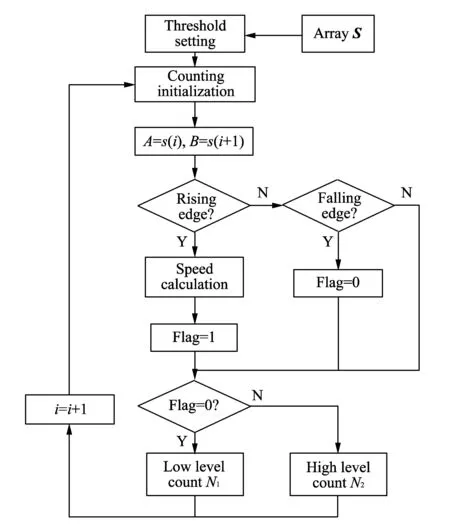
Fig.2 Flow chart of instantaneous rotation speed measurement algorithm
2 Error analysis and processing
2.1 Error analysis
The speed measurement error mainly results from installation eccentricity of the speed disk, tooth profile machining error, vibration of the carriage and data quantization error[9-11].
The installation eccentricity of the speed disk causes relative motion in the radial and tangential directions between the sensor and speed disk. The relative radial movement modulates the amplitude of the output signal, and the relative tangential motion results in frequency modulation. Monitoring the amplitude and frequency modulation (AM-FM) signals can obtain the installation and operation status information of coupling[12]. Tooth profile machining error is inevitable, which can be eliminated by calibration and average methods; The error caused by vibration of the carriage is random, which can also be decreased by average method[13-14]. The data quantization error is caused by lower sampling frequency of the data acquisition card; the higher the frequency is, the less the error is.
2.2 Data quantization error
Eq.(1) shows that the accuracy of instantaneous rotation speed measurement lies on the number of gear teethZ, the sampling frequency of the data acquisition cardfsand the sampling number during a square wave cycleK. The number of gear teeth is a mechanical parameter and is not changed easily. Therefore, the accuracy directly depends on the sampling frequency and sampling number.
Suppose thatnfis the sampling number once reading from the buffer, the sampling time ist=nf/fs. During the sampling time, the number of the square wave cycle isN. The instantaneous rotation speedncan be written as
In the process of counting,K=nf/Nhas error ±1 after being rounded, and its quantization error isεr=±fs/K. After setting the sampling frequency and sampling time,nfis constant. At the moment,Ndepends on the frequency of input signal. The lower the frequency is, the smallerNis and the smaller the quantization error ofKis; otherwise, the higher the frequency is, the bigger the quantization error is.
2.3 Error simulation analysis
The square wave simulation signal with the frequency of 678 Hz is generated based on Matlab. When the sampling time is 1 s, at different sampling frequencies, the instantaneous frequency measurement error values are compared and comparison results are shown in Table 1.
Table 1 Effect of sampling frequency on instantaneous frequency measurement
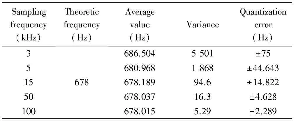
Samplingfrequency(kHz)Theoreticfrequency(Hz)Averagevalue(Hz)VarianceQuantizationerror(Hz)351550100678686.5045501±75680.9681868±44.643678.18994.6±14.822678.03716.3±4.628678.0155.29±2.289
It can be seen from Table 1 that with the increase of the sampling frequency, the measurement error can be reduced, which is conducive to improvement of measurement accuracy and reduction of measurement variance and quantization error.
3 Speed measurement system
3.1 Variable speed hydraulic system
The schematic diagram of variable speed hydraulic system is shown in Fig.3[15].

Fig.3 Schematic diagram of variable speed hydraulic system
In Fig.3, variable frequency motor 13 drives hydraulic pump 14 to control the rotation speed of the piston motor 3. The oil passes through the filter 15 and checks valve 12 to set up the pressure by variable frequency motor driving pump. The pressure oil passes through change valve 9 to change the rotation direction of piston motor and drive it to work with load. Servo controller 18 controls the variable frequency motor to change the output flow of the pump. The flow rate of the system is proportional to the input voltage of servo controller and the speed change of piston motor is consistent with the flow of the system.
Speed disk 4 is mounted on the input shaft of reducer 5, by pressing on the coupling. When the piston motor works with load, the speed disk rotates with the piston motor, and its speed is the same as the speed of piston motor. Magnetic sensor transmits speed information to the IPC in the form of a square wave signal. After the data acquisition card samples the signal, the instantaneous speed can be obtained by programming.
3.2 Speed measurement system based on IPC
The speed measurement system diagram based on IPC is shown in Fig.4.

Fig.4 Speed measurement system diagram based on IPC
The speed square wave signal of hydraulic motor passes through the data acquisition card to communicate with upper computer. In the developed speed measurement system, the instantaneous speed is calculated, and it can be displayed or preserved in the human-computer interface based on LabVIEW.
Using hybrid programming approach of LabVIEW and Matlab to develop speed measurement system can implement the instantaneous speed measurement based on data acquisition card and IPC. As shown in Fig.4, the data acquisition card samples the signal of hydraulic system, and the speed square wave signal is extracted by means of LabVIEW. The signal passes through MATLAB Script node and the speed value is calculated. Finally, by external node interfaces, the value is transmitted to the human-computer interface based on LabVIEW for display and preservation.
4 Experiment and analysis
4.1 Static response analysis
The speed of variable frequency motor is set at 300 r/min. The sampling frequency is set at 5 kHz, 10 kHz, 15 kHz, 20 kHz, respectively. The speed measurement diagram of piston motor is shown in Fig.5.
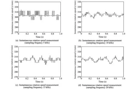
Fig.5 Instantaneous rotation speeds under different sampling frequencies
It can be seen from Fig.5 that with the increase of sampling frequency, because of the output speed fluctuations of hydraulic piston motor, the transient information of rotation speed is obvious. The statistical characteristics are shown in Table 2.
Table 2 Statistical characteristics of speed measurement under different sampling frequencies

Samplingfrequency(kHz)Measurementaverage(rpm)MeasurementvarianceQuantizationerror(rpm)5304.34322.008±4.73110304.29710.573±2.33115304.2449.791±1.54620304.1727.872±1.157
Table 2 shows that, when the sampling frequency increases from 5 to 20 kHz, the instantaneous rotation speed measurement variance is diminished obviously from 22.008 to 7.872. The quantization error is also decreased from ±4.731 to ±1.157 r/min. The measurement result is of high accuracy.
4.2 Dynamic response analysis
The speed of variable frequency motor changes as step, slope and sine regulations, respectively. The change of rotation speed of hydraulic piston motor is the same as that of variable frequency motor. In order to reduce the influence of quantization error on instantaneous rotation speed measurement, with the sampling frequency of 50 K, when the rotation speed reaches the maximum (620 r/min), the quantization error is reduced to ±1.917 r/min; the lower the rotation speed, the smaller the quantization error. The instantaneous speed measurement dynamic response diagram of piston motor is shown in Fig.6.
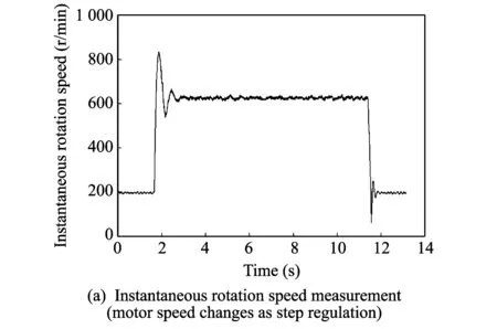

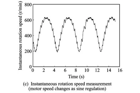
Fig.6 Instantaneous rotation speed dynamic response diagram
It can be seen from Fig.6 that, with the increase of the sampling frequency, the quantization error is dramatically reduced, which is beneficial to measuring the change of instantaneous rotation speed during dynamic response process for variable speed hydraulic system.
5 Conclusion
In this paper, by means of hybrid programming approach of LabVIEW and MATLAB, the speed measurement system is developed to implement the instantaneous speed measurement based on data acquisition card and IPC. Error analysis indicates that the data quantization error is the major error source of the rotation speed measurement based on data acquisition card and IPC, which has an obvious effect on the instantaneous speed. The higher the simpling frequency of the data acquisition card, the less the quantization error. Therefore, increasing the sampling frequency can reduce the measurement error, improve accuracy and detect the dynamic change process of instantaneous rotation speed.
[1]XI Song-tao, CAO Hong-rui, CHEN Xue-feng, et al. A frequency-shift synchrosqueezing method for instantaneous speed estimation of rotating machinery. Journal of Manufacturing Science and Engineering, 2015, 137(3): 031012-11.
[2]MA Lei, Melkote S N, Castle J B. A model-based computationally efficient method for on-line detection of chatter in milling. Journal of Manufacturing Science and Engineering, 2013, 135(3): 031007-11.
[3]LIA Yu-hua, GUA Feng-shou, Harris G, et al. The measurement of instantaneous angular speed. Mechanical Systems and Signal Processing, 2015, 19(4): 786-805.
[4]Gubran A A, Sinha J K. Shaft instantaneous angular speed for blade vibration in rotating machine. Mechanical Systems and Signal Processing, 2014, 44(1/2): 47-59.
[5]Stander C J, Heyns P S. Instantaneous angular speed monitoring of gearboxes under non-cyclic stationary load conditions. Mechanical Systems and Signal Processing, 2005, 19(4): 817-835.
[6]GU Yu-hai, HAN Qiu-shi, XU Xiao-li. Research of high-accurate rotating speed method. Instrument Technique and Sensor, 2013, (10): 88-90.
[7]LIU Wei-guo, CHEN Jia-hua, ZHANG Li-mei, et al. The instantaneous speed measurement of internal combustion engine. Transactions of CSICE, 1999, 17(4): 388-390.
[8]ZHENG Zhe, ZHANG Ren-jie. Classification research of rotation speed measurement. Applied Mechanics and Materials, 2014, (457/458): 998-1003.
[9]Espadafor F J J, Villanueva J A B, Guerrero D P, et al. Measurement and analysis of instantaneous torque and angular velocity variations of a low speed two stroke diesel engine. Mechanical Systems and Signal Processing, 2014, 49(1/2): 135-153.
[10]Renaudin L, Bonnardot F, Musy O, et al. Natural roller bearing fault detection by angular measurement of true instantaneous angular speed. Mechanical Systems and Signal Processing, 2010, 24(7): 1998-2001.
[11]HU Yu-ping, WU Bo, ZHANG Li-mei. Analysis of measured errors of transient speed in internal combustion engines. Journal of Shandong University of Technology, 2001, 31(5): 408-415.
[12]WANG Yuan-wen, DONG Da-wei, YAN Bing. Influence mechanism and law of sensor working clearance on instantaneous engine speed measurements. Transactions of CSICE, 2014, 32(5): 466-473.
[13]ZHANG Yong-xiang, SUN Yun-ling, LI Jun, et al. Research on transient rotation speed measurement errors process technology for diesel engines. Chinese Internal Combustion Engine Engineering, 2005, 26(6): 61-63.
[14]WANG Xi-bo, PENG Hai-yong, DENG Kang-yao. Method and implement of measuring the revolution speed with data acquisition card. Transactions of the Chinese Society for Agricultural Machinery, 2007, 38(2): 72-75.
[15]JIA Yong-feng, GU Li-chen. System design and experimental analysis for hydraulic power unit with permanent magnet synchronous motor drive. China Mechanical Engineering, 2014, 23(9): 1239-1243.
变转速液压系统瞬时转速测量与误差分析
杨 彬1, 谷立臣1,2, 刘 永1,3, 王 平1
(1. 长安大学 公路养护装备国家工程实验室, 陕西 西安 710064;2. 西安建筑科技大学 机电工程学院, 陕西 西安 710054;3. 湖北汽车工业学院 机械工程学院, 湖北 十堰 442002)
为实时监测柱塞马达的运行状态, 准确测量瞬时转速, 结合基于工控机与数据采集卡的瞬时转速测量原理与算法, 讨论了数据量化误差的主要来源、 影响机理以及处理方法, 利用LabVIEW与Matlab混合编程的方法, 设计了变转速液压系统柱塞马达瞬时转速的测量系统, 通过实验验证了测速系统的可行性。 仿真与实验结果表明, 采样频率对马达转速测量具有重要影响。 提高采样频率可以减小数据量化误差、 提高测量精度。
变转速液压系统; 瞬时转速; 误差分析; 混合编程
YANG Bin, GU Li-chen, LIU Yong, et al. Instantaneous rotation speed measurement and error analysis for variable speed hydraulic system. Journal of Measurement Science and Instrumentation, 2015, 6(4): 315-321.
10.3969/j.issn.1674-8042.2015.04.002
Foundation items: National Natural Science Foundation of China (No. 51275375, No. 51509006); Shaanxi Provincial Natural Science Basic Research Plan (No.2014JQ7246); The Science and Technology of Hubei Province(No. B2015115) and Doctoral Research Foundation of Hubei University of Automotive Technology (No. BK201403)
YANG Bin (chdsy_yb@163.com)
1674-8042(2015)04-0315-07 doi: 10.3969/j.issn.1674-8042.2015.04.002
Received date: 2015-10-08
CLD number: TP271+.31 Document code: A
猜你喜欢
中国机械工程(2022年22期)2022-11-25
机械工程与自动化(2022年3期)2022-06-24
中国机械工程(2022年7期)2022-04-20
装备制造技术(2020年11期)2021-01-26
钻采工艺(2020年1期)2020-07-21
中国机械工程(2019年17期)2019-09-19
中国机械工程(2018年4期)2018-03-06
小学生导刊(2017年15期)2017-05-17
棋艺(2016年4期)2016-09-20
中国塑料(2016年3期)2016-06-15
 Journal of Measurement Science and Instrumentation2015年4期
- Journal of Measurement Science and Instrumentation的其它文章
- Sensors layout optimization in explosion overpressure field reconstruction
- Experimental study on gas explosion to kill and injury mouse
- Fault diagnosis and analysis of main sea water pump based on vibration monitoring in offshore oil field
- Uncertainty contribution at NIS phototherapy irradiance facility
- Effects of interior ballistic factors on dispersion of central blast tube cluster munitions
- Symmetric axis detection for images based on Hough algorithm