
Fluid simulation of internal leakage for continuous rotary electro-hydraulic servo motor①
2016-12-29 05:34WangXiaojing王晓晶ZhangMengjianManGuojiaCaoJianXiuLiwei
High Technology Letters 2016年4期
Wang Xiaojing (王晓晶), Zhang Mengjian, Man Guojia, Cao Jian,Xiu Liwei
(*School of Mechanical and Power Engineering, Harbin University of Science and Technology, Harbin 150080, P.R.China)(**School of Mechanical and Electrical Engineering, Harbin Institute of Technology, Harbin 150080, P.R.China)
Fluid simulation of internal leakage for continuous rotary electro-hydraulic servo motor①
Wang Xiaojing (王晓晶)②*, Zhang Mengjian*, Man Guojia*, Cao Jian**,Xiu Liwei*
(*School of Mechanical and Power Engineering, Harbin University of Science and Technology, Harbin 150080, P.R.China)(**School of Mechanical and Electrical Engineering, Harbin Institute of Technology, Harbin 150080, P.R.China)
The internal leakage has important influence on low speed performance of continuous rotary electro-hydraulic motors, and research on internal leakage is of important significance to improve the motor low speed performance. UG software is adopted to establish a flow field inside a motor, which ignores the gap between the blade and the blade groove, and a motor fluid model in different working conditions is established. Using ICEM-CFD to generate high-quality O-Net mesh for meeting the computing requirements, the flow field inside the motor is simulated using fluid simulation software CFX. Applying reasonable boundary conditions and then solving it, pressure field distribution and the variation rule of internal leakage with different pressure difference in the flow field are obtained when the clearance value of the motor key components is 0.01mm. At the same time the motor’s leakage experiment has also been done to verify the validity of the simulation results, which lays a foundation for the study of motor internal leakage effect on the low speed performance.
continuous rotary motor, leakage, low speed performance, finite element analysis
0 Introduction
Rapid development of hydraulic technology not only broadens the application scope of hydraulic system, but also accelerates the research on hydraulic pump and hydraulic motor[1,2].At present China’s power keeps rising in aerospace and military technology, so aircraft’s precision and controllability requirements are becoming more stringent. The flight simulator is an important experimental equipment of flight control system simulation, whose performance affects the fidelity of flight simulation results directly, and continuous rotary electro hydraulic servo motor must have good properties as directly driving the heavy load hydraulic simulator, such as super-low speed, wide control, high precision and fast dynamic response, etc[3-5]. The minimum stable speed of a continuous rotary electro-hydraulic servo motor is 0.001°/s, and factors affecting the low speed performance include friction and leakage characteristics of motor, servo valve resolution, load friction characteristics and oil source pressure pulsation, etc., the most important of which is friction and leakage characteristics of motor[6-8]. Friction not only affects system dynamic and static characteristics, but also easily causes low ripple and a creeping phenomenon in the system[9-11]. In addition, the damping ratio of the hydraulic motor system can be improved by motor internal leakage. But at the same time system stiffness will be reduced, so that the system anti-interference ability is reduced in low speed running[12,13]. Thus the real problem of improving motor’s low speed performance is attributed to the study of friction and leakage characters.
In order to master the internal leakage changing rule affecting motor’s low speed performance, in this work, motor’s leakage characteristics will be studied in detail. First of all, motor’s internal leakage parts are analyzed, and then physical models are established by UG software. The finite element simulation is implemented on the flow field within motor with ANSYS workbench software[14-16]. The internal flow field distribution of continuous rotary motor is obtained under different inlet and outlet pressure, and the changing rule of motor’s seal chamber pressure field and motor’s internal leakage with pressure difference are revealed and proved by the experiment, which provides powerful basis for improving the motor low speed performance.
1 Working principle of continuous rotary motor
The working principle diagram of vane type continuous rotary electro-hydraulic servo motor is shown as Fig.1, which is composed of a vane, a rotor, an oil distribution casing and a stator, where the stator inner curve includes two arcs with long radius, two arcs with short radius and eight transition curves for connecting the long and short radiuses. When the motor does not start, the vane under the effect of pre-compression spring extends along the vane groove and the vane top is pressed against the stator inner surface to form a closed chamber inside the motor.

Fig.1 The working principle diagram of continuous rotary electro-hydraulic servo motor
After the motor is started, hydraulic oil is supplied to each oil-way by hydraulic pump. Firstly hydraulic oil is supplied by electro-hydraulic servo valve to inlet chamber 1 and inlet chamber 2 which is distributed as radial symmetric in the oil distribution casing. After the high-pressure oil flows into the motor sealed cavity, an effect torque is put on the blades, so as to drive the rotor to rotate. As the motor runs, the blades along the rotor slot continue to slide constantly. In arc transition curve of the stator, the cavity fluid between blades root and blades top is interlinked in order to make the blade always to keep a close contact with the stator inner surface. And on the four arcs with long and short radius, the oil from the blades root is supplied by relief valve in order to ensure that the blades can be close to the stator surface, so as to ensure a closed container cavity. Therefore, when the blades rotate from the stator arc segment to transition curves, the pressure in the root is changing. The leak site exists in the arc segment of stator curves, and between the vane and stator inner surface, between the vane end face and oil distribution plate, between the rotor end face and oil distribution plate, and between the vane and the vane groove.
2 Flow field analysis of continuous rotary electro-hydraulic servo motor
2.1 The creation of fluid computing model
Due to the special structure of continuous rotary electro-hydraulic servo motor, the leakage only exists in the arc segment of stator curve. For this purpose, the flow field distribution is studied where there are two blades in the long radius arc section of stator inner curve and two blades in the short radius arc section of stator inner curve, and in this case a blade exists in the other arc segment of stator curve, so the four fluid flowing models could just express the entire variation of pressure field in the seal chamber. The leakage direction between the vane and vane slot is complex because of the special motor structure, and its impact on the whole leakage model is small and the modeling is complex, so when the flow field is modeled inside the motor, leakage is ignored between the vane and vane groove, considering the leakage between the stator inner surface and the blade, blade end face and the oil distribution plate, and the rotor end surface and the oil distribution plate. Using Unigraphics to model the solid which is shown in Fig.2. Fig.2(a) is the fluid model of a blade in the long radius arc of stator curves, Fig.2(b) is the fluid model of two blades in the long radius arc of stator curves, Fig.2(c) is the fluid model of a blade in the short radius arc of stator curves, and Fig.2(d) is the fluid model of two blades in the short radius arc of stator curves.

Fig.2 Fluid models of various parts of the motor
2.2 Grid division
The fluid model structure is complex in this study, because there is size distortion at the vane top, and the minimum gap value is 0.01mm between the vane top and the stator inner surface, the end face of the rotor and the oil distribution plate, whose size is too much different between the surrounding structure, and the shape and the structure of blade top is also very irregular, which make it more difficult to build a structured grid, and it needs to try different methods to generate high-quality meshes. So the difficulties of this study is to mesh fluid model, in general, somewhere physical changes drastically, the grid unit size should be relatively small, and permutations need to be more close[17,18]. Therefore, CFD ICEM is used to divide the fluid model grid, which has a good grid division function and a rich solver interface, and can output grid for CFD and FEA software[19]. Comprehensive considering various factors, the size distortion part of the top gap is parted from other sections, and then the size distortion position is divided into several parts again. By creating mapping to generate O-Net meshing, the grid of flow sensitive region is encrypted. The grid of motor flow model is shown as Fig.3, and grid convergence check all through, which meets the computational requirement.

Fig.3 The grid of fluid models in motor
2.3 Settings of boundary conditions
When calculating flow field distribution of continuous rotary motor at different inlet and outlet pressure difference, the boundary conditions consist of inlet and outlet pressure boundary, symmetric periodic boundary, fixed wall boundary and rotating wall boundary. The inlet and outlet pressure boundary is set to get the motor leakage in different inlet and outlet pressure difference, so when the oil source pressure is 12 MPa, respectively, inlet and outlet pressure value is shown in Table 1, and the change rule of leakage can be obtained when inlet and outlet pressure difference is 1MPa、2MPa、3MPa、4MPa、5MPa. In this work, 32#hydraulic oil is chosen, and hydraulic oil viscosity change will affect flow field distribution, so the pressure field distribution within the motor is considered under varying viscosities[20]. The relationship of dynamic viscosity and temperature is shown as Fig.4.

Fig.4 viscosity-temperature curve of 32# hydraulic oil

BoundarypressurevaluesInletpressure(MPa)8.587.576.5Outletpressure(MPa)3.544.555.5
3 Simulation results and Analysis
Under the conditions of variable viscosity, simulation analysis is done by changing working conditions. Due to the length limit of this paper, the change law of pressure field is listed only when pressure difference is 1MPa, 3MPa, and 5MPa in the motor working chamber, as shown in Fig.5 to Fig.8.
(1) When there is a blade in the long radius arc of the stator inner curves, the pressure field distribution with different pressure difference is shown in Fig.5.
(2) When there are two blades in the long radius arc of the stator inner curves, the pressure field distribution with different pressure difference is shown in Fig.6.
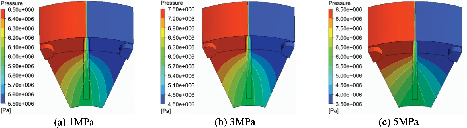
Fig.5 Pressure field distribution with a blade in the long radius arc of stator inner curves

Fig.6 Pressure field distribution with two blades in the long radius arc of stator inner curves
(3) When there is a blade in the short radius arc of the stator inner curves, the pressure field distribution with different pressure difference is shown in Fig.7.

Fig.7 Pressure field distribution with a blade in the short radius arc of stator inner curves
(4) When there are two blades in the short radius arc of the stator inner curve, the pressure field distribution with different pressure difference is shown in Fig.8.

Fig.8 Pressure field distribution with two blades in the short radius arc of stator inner curves
Simulation results show that the flow pressure field distribution within the motor is not evenly uniform, but shows some regular distribution that the inlet pressure is the maximum, the outlet pressure is the minimum, and the pressure transits gradually from high to low pressure chamber. Pressure cloud shows that the pressure field distribution under different pressure difference is the same. When only one blade in the long radius arc, there is a clear transition zone in the blade top connection between the high and low pressure chamber, and the pressure gradually decreases from the high pressure chamber to the low pressure chamber, and the transition of blade end face is more gentle and no obvious transition zone. While these are two blades in the long and short radius arc, in the region between two vanes, there is a relatively less obvious transition zone in the blade top and end face between high and low pressure chamber, and no negative pressure occurs.
In order to obtain the motor internal leakage, an example of fluid model was given when the long radius arc has two blades and pressure difference is 1MPa. By Function Calculator under Calculators of CFX software, the cross-section was established on one of blades’ top which is named Plane1, according to the operation shown as Fig.9, and then clicking Calculate to get the leakage through the blade top of the arc segment when the gap is 0.01mm. The motor mass flow in other location and under different pressure difference can be obtained by the same method. When two blades exist in the long and short radius arc, the leakage can be determined at different pressure difference, and hydraulic oil as incompressible fluid, the mass flow will eventually be converted into volume flow. Under different working conditions, when two blades exist in the long radius arc, the results are shown as Table 2. When two blades exist in the short radius arc, the results are shown as Table 3.

Fig.9 The mass flow through the Plane 1

Pressuredifference(MPa)12345Leakage(L/min)0.5375×10-30.9648×10-31.3292×10-31.6624×10-31.9691×10-3

Table 3 The results under different pressure difference when two blades exist in short radius arc
Thus the change curves of gap leakage flow of continuous rotary motor with the pressure changing can be obtained, as shown in Fig.10, where curve 1 is the curve that the gap leakage flow changes with the pressure difference when two blades exist in the long curve radius arc, and curve 2 is the curve that the gap leakage flow changes with the pressure difference when two blades exist in the short curve radius arc.

Fig.10 The leakage change curve with pressure difference
From Fig.10, the pressure difference is proportional to the internal leakage of continuous rotary electro-hydraulic servo motor, and the greater the pressure, the greater the amount of leakage within the motor. Therefore in order to reduce the internal leakage, it does not only reduce the gap with the motor inside surfaces, but also control the pressure difference between the inlet and the outlet of the motor, thereby improving the low speed performance of continuous rotary motor.
4 Experiment
The purpose of this experiment is to make a quantitative measurement of leakage produced by the motor. The hydraulic system circuit of leakage experiment is shown in Fig.11, where the dashed line represents valve block, the motor’s high pressure chamber is connected to port A, and low pressure chamber is connected to port B. The oil of blade root is connected to a pressure reducing valve by pk, and 1, 2 and 3 represents the globe valve, psrepresents the oil inlet, and O represents the outlet.

Fig.11 Circuit sketch of hydraulic system
Neglecting the effect of the servo valve leakage on the motor leakage, the experiment process is as follows: Setting oil source pressure psto be respectively 1 MPa, 2 MPa, 3 MPa, 4 MPa, 5 MPa, and ps/2 to be dispatched as the reducing valve pressure. Secondly starting the motor, closing stop valve 2, opening stop valve 3, finally collecting leakage within 10s, and the average of multiple measurements is calculated. The result is shown in Fig.12, Curve 1 represents motor leakage with pressure difference when the servo valve opening is positive, and Curve 2 represents motor leakage with pressure difference when the servo valve opening is reversed. As Fig.11 shows, the motor leakage is high, and the leakage increases with the increasing of pressure difference. So the results of experiment and simulation are uniform on the change trend, which verifies the correctness of simulation results.

Fig.12 Experimental curves of leakage under different pressure difference
5 Conclusion
Through the working principle analysis of continuous rotary electro-hydraulic servo motor, the internal leakage position is determined, and using UG to establish the flow field simulation model, the distribution rule of pressure field in the different condition of the motor is obtained by using ANSYS CFX. The simulation results of the pressure field under different pressure difference show that pressure field distribution is not uniform, and there is no pressure jump, but a gradual transition from the maximum pressure to the minimum pressure in accordance with the actual working conditions of the motor. The change rule of internal leakage in various position of continuous rotary electro hydraulic servo motor is obtained, and the pressure difference is proportional to motor internal leakage. The experiment equipment is built for continuous rotary electro-hydraulic servo motor, and the motor leakage experiment is practiced under the oil pressure of 12MPa. The experimental results show that the leakage is proportional to the pressure difference, which has the same change trend with the result of motor finite element analysis. So the correctness of simulation result is verified, which not only lays the foundation for the motor structure design optimization, but also lays the foundation for studying the leakage effect on the motor low speed performance.
[ 1] Wang Y Q, Zhang W. Summary of fluid power transmission and control technology. Chinese Journal of Mechanical Engineering, 2003, 39(10): 95-99
[ 2] Yang H Y, Pan M. Engineering research in fluid power: a review. Journal of Zhejiang University-Science A(Applied Physics & Engineering), 2015, 16(6): 427-442
[ 3] Tao J F, Wang X Y, Liu C L. Five-axis flight simulators and their key techniques. Machine & Hydraulic, 2006, (6): 78-82
[ 4] Guo J, Low-speed performance and predictive functional control of hydraulic simulator: [Ph.D dissertation]. Harbin: School of Mechatronics Engineering, Harbin Institute of Technology, 2012. 85-102 (In Chinese)
[ 5] He Y H. Research on performance of continuous rotation electro-hydraulic servo motor based on controller: [Master’s thesis]. Harbin: School of Mechatronics Engineering, Harbin Institute of Technology, 2010. 2-6 (In Chinese)
[ 6] Wang X J, Jiang J H, Li S Y. Study on the leakage of the continuous rotary electro-hydraulic servo motor. Machine & Hydraulic, 2008, 36(10):54-56
[ 7] Cao J, Li S Y, Zhao K D. Low-speed friction and performance of new continuously rotating electro-hydraulic servomotor. Journal of Harbin Institute of Technology, 2003, 35(2): 142-146
[ 8] Wu X F. Research on performance of continuous rotation electro-hydraulic servo motor: [Master’s thesis]. Harbin: School of Mechatronics Engineering, Harbin Institute of Technology, 2009. 3-36 (In Chinese)
[ 9] Yuan B. Simulation of Hydraulic Motor low speed performances considering nonlinear friction torque. Journal of Wuhan University of Technology(Transportation Science& Engineering), 2002, 26(2): 277-279
[10] Peng X W, Geng Q B, Wang X P. Experimental study on low-velocity friction torque characteristics of hydraulic motor. Transactions of Beijing Institute of Technology, 2006, 26(11): 999-1003
[11] Jia S N. Frictional and experimental research on electro-hydraulic servo motor to simulator: [Master’s thesis].Harbin: School of Mechatronics Engineering, Harbin Institute of Technology, 2007. 6-52 (In Chinese)
[12] Yuan L P, Cui S M, Lu H Y, et al. Research on low speed performance of electro-hydraulic servomotor based on improved simulated annealing genetic algorithm. Journal of Shanghai Jiaotong University, 2010, 44(12): 1742-1746
[13] Jiang W B, Liu S K, Zou B H. Research on simulation of hydraulic motor’s low speed stabilitty based on MATLAB/Simulink. Mining and Metallurgical Engineering, 2008, 28(1): 94-96
[14] Ling G L. ANSYS workbench15.0 from entry to the master. Beijing: Tsinghua University Press, 2014. 25-70
[15] Mao Z Q. Simulation and analysis of helical gear pump flow field based on fluent: [Master’s thesis]. Lanzhou: College of Energy and Power Engeering, Lanzhou University of Technology,2014. 12-45 (In Chinese)
[16] Gong J K, Cai H, Liu Y Q, et al. CFD analysis and experimental research on the internal flow field in rotor oil pump. Journal of Hunan University(Natural Sciences), 2007,34(5):24-28
[17] Wang C, Liu Y M, Zhou T, et al. Optimization of mesh generation of steam turbine last stage 3D blade field based on ICEM CFD. Turbine Technology,2012,54(5): 324-326
[18] Yang Q. Simulation and analysis on the internal flow in centrifugal pump based on different turbulence models: [Master’s thesis]. Lanzhou:College of Energy and Power Engeering, Lanzhou University of Technology, 2010. 6-59 (In Chinese)
[19] Ji B B, Chen J P. ANSYS ICEM CFD Meshing Technology Example Explanation. Beijing: China Water Conservancy and Hydropower Press , 2013. 153-301
[20] Yang X D, Shao J P, Mu X N. Numerical and experimental studies on fluid- solid interaction heat transfer of heavy vertical lathe rotary-table. Transactions of the Chinese Society for Agricultural Machinery,2014,45(7):292-300
Wang xiaojing, born in 1981. She received her PH.D degrees in School of Mechanotronics Engineering of Harbin Institute of Technology in 2009. Her research interests include fluid transmission and control, optimum design of hydraulic components and novel hydraulic device.
10.3772/j.issn.1006-6748.2016.04.015
① Supported by the National Natural Science Foundation of China (No. 51305108), Heilongjiang Province Ordinary Higher School Youth Academic Backbone Support Program (No.1254G025) and Post Doctoral Researchers Settled in Heilongjiang Research Start Funding Projects (No. LBH-Q15069).
② To whom correspondence should be addressed. E-mail: hitwangxiaojing@163.com Received on Jane 6,2016
 High Technology Letters2016年4期
- High Technology Letters的其它文章
- Clustering approach based on hierarchical expansion for community detection of scientific collaboration network①
- Integration of naval distributed tactical training simulation system based on advanced message queuing protocol①
- A visual awareness pathway in cognitive model ABGP①
- Measurements and analysis at 400MHz and 2600MHz in corridor radio channel①
- A buffering method for quadruped robots based on active impedance control①
- Fuzzy image restoration using modulation transfer function①