
An efficient QoS enhancement mechanism of VoIP using erasure array codes①
2017-12-19 00:39LiZhenRenHuiLiuWenboGaoXinyan
High Technology Letters 2017年4期
Li Zhen (李 真), Ren Hui, Liu Wenbo, Gao Xinyan
(*School of Information Engineering, Communication University of China, Beijing 100024, P.R.China) (**School of Software, Dalian University of Technology, Dalian 116024, P.R.China)
An efficient QoS enhancement mechanism of VoIP using erasure array codes①
Li Zhen (李 真)②, Ren Hui*, Liu Wenbo**, Gao Xinyan**
(*School of Information Engineering, Communication University of China, Beijing 100024, P.R.China) (**School of Software, Dalian University of Technology, Dalian 116024, P.R.China)
In order to solve the problem of losing voice packets in voice over internet protocol (VoIP), a kind of lost packets double recovery algorithm is proposed. The algorithm is based on erasure coding technique which comes from highly available data storage systems. An efficient coding scheme with higher tolerance based on STAR and Reed-Solomon (RS) erasure code is described. An efficient method is also provided which could transform the voice data packets of one dimensional bit stream into two dimensional array according to given window size. If the lost rate has increased beyond the error correction capability, packet-loss concealment will be adopted. Under various conditions of packet-loss simulation during the experiments, the algorithm has proved its better performance on MOS rating and coding rate.
packet loss recovery, voice over internet protocol (VoIP), quality of service (QoS), array code
0 Introduction
It is well known that VoIP is a real-time transport protocol running on top of the user datagram protocol (UDP). Quality of service (QoS) is a major issue in VoIP applications. However, UDP is an unreliable delivery protocol. When routers of the packet-switched network are overloaded, some voice packets will be lost inevitably. Moreover, in real-time communications a voice packet that arrives at the receiving endpoint too late will be useless and has to be disregarded correspondingly. When losing packets happens, the quality of the audio at the receiving endpoint degrades greatly.
To defend the problem of lost packets, researchers have proposed two classes of techniques for improving QoS, which are sender-based techniques and receiver-based techniques respectively, where receiver-based techniques employ packet-loss concealment algorithms to synthesize audio when packets of audio data are missing, while for sender-based loss-recovery techniques, the sender acts an active role to help the receiver recover lost information to improve QoS when packet loss occurs. Most sender-based lose-recovery methods work by transmitting redundant data to some degree. These approaches will consume additional resources such as network bandwidth and CPU capacity, which will conversely make the losing packet problem worse. Therefore, there should make a reasonable trade-off between additional resource consumption and redundant degree.
Sender-based loss-recovery techniques typically introduce extra end-to-end delay into the media stream. Generally, humans cannot even perceive a one-way delay of less than 100ms, and most users can tolerate a one-way delay of up to 250ms. If the one-way delay exceeds 250ms, however, the delay would result in a serious talker-overlap effect that is intolerable for most users[1]. Therefore, additional delays should be considered as well as other factors such as bandwidth consumption when evaluating the feasibility and effectiveness of loss-recovery techniques.
In data storage systems, there exists a big family of coding schemes which can be used to correct storage node failure for a given data redundancy. Maximum distance separable (MDS)[2]array codes are such error-correcting codes that have important applications in communication and highly available storage systems such as redundant arrays of inexpensive disks (RAID) architecture.
Up to now, a number of MDS array codes have been studied, such as EVENODD[3], B-code[4], X-code[5], row-diagonal parity (RDP)[6], STAR code[7], zigzag code[8], etc.
In general, an array code consists of arrays of size m×n, with each element of an array storing one symbol, which can be a simple bit, a byte or a binary string for any length. Among the n columns, k columns store the information symbols and r columns store the parity-check symbols (n=r+k). If the array code can tolerate any r storage node erasures, in an MDS array code, the information symbols can be recovered from any k columns.
Most of them are designed to correct multiple node erasures. For example, the RDP code and the EVENODD code can tolerate any two node erasures. MDS array codes such as the generalized EVENODD, STAR, Triple-Star[9]and generalized RDP can tolerate any three erasures.
Recently, array codes have been further studied and gradually applied to overcome the lost packets problem in real-time data communication area. In 2010,1-D interleaved parity codes were standardized by internet engineering task force (IETF) in request for comments (RFC) 6015 to recover lost packets in real-time transport protocol over UDP to transport data packets.
Generally, the sender-based techniques are independent of the receiver-based techniques, so designers can combine both types of loss-recovery methods simultaneously.
In this paper, the sender-based forward error correction technique is mainly focused on and the array code scheme (STAR code) is applied with multiple erasure correction capacity to construct a packets loss-recovery approach. The STAR code also combines with the traditional RS code which is always used in the sender-based loss-recovery. The key procedure of our method is to transform the original bit stream into two dimensional packet array under different losing models. When packets losing occur, the receiver will fill the lost packets with zero and perform erasure recovery process. If the lost column number is no more than the capacity of the array code, all lost packets will be recovered thoroughly. Otherwise, the lost packets will be discarded and a new shorten bit stream will be reconstructed from the received array. Then the WSOLA[10]algorithm will be carried over the new-generated bit stream.
Based on the above considerations, an approach combining both sender-based and receiver-based techniques is proposed for VoIP communications QoS enhancement under various packet-loss conditions.
The remainder of this paper is structured as follows. In Section 1, the main principles of STAR code and RS-code are recapitulated. The modified packet-level encoding and decoding algorithms are detailed for communication scenario. In Section 2 an overall algorithm framework is provided for packet-loss recovery and concealment and a prototype implementation is also presented. In Section 3, the performance of the approach is extensively evaluated for different types and levels of packet loss and for different byte rates. The effectiveness of different techniques is compared. In the Section 4, main conclusions are summarized.
1 Packet-level array encoding and decoding
First the problem definition is described briefly which was initially proposed to address disk failures in RAID systems[6,7].
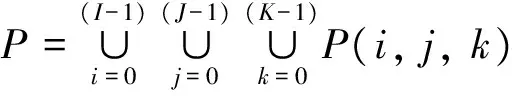
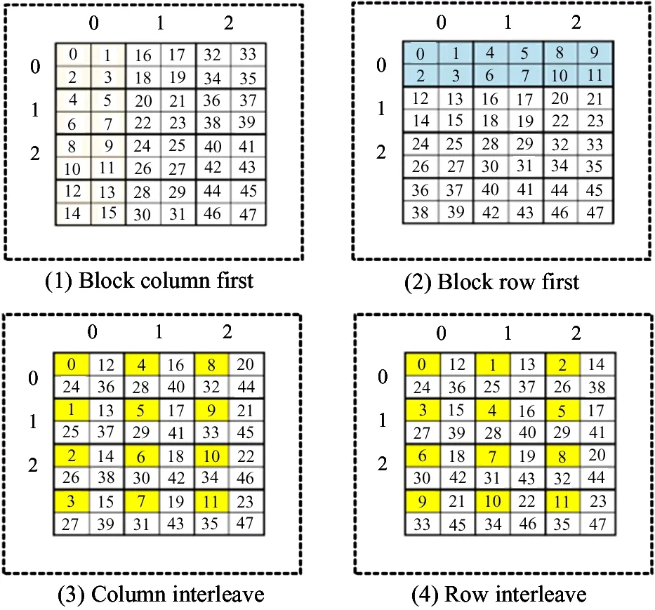
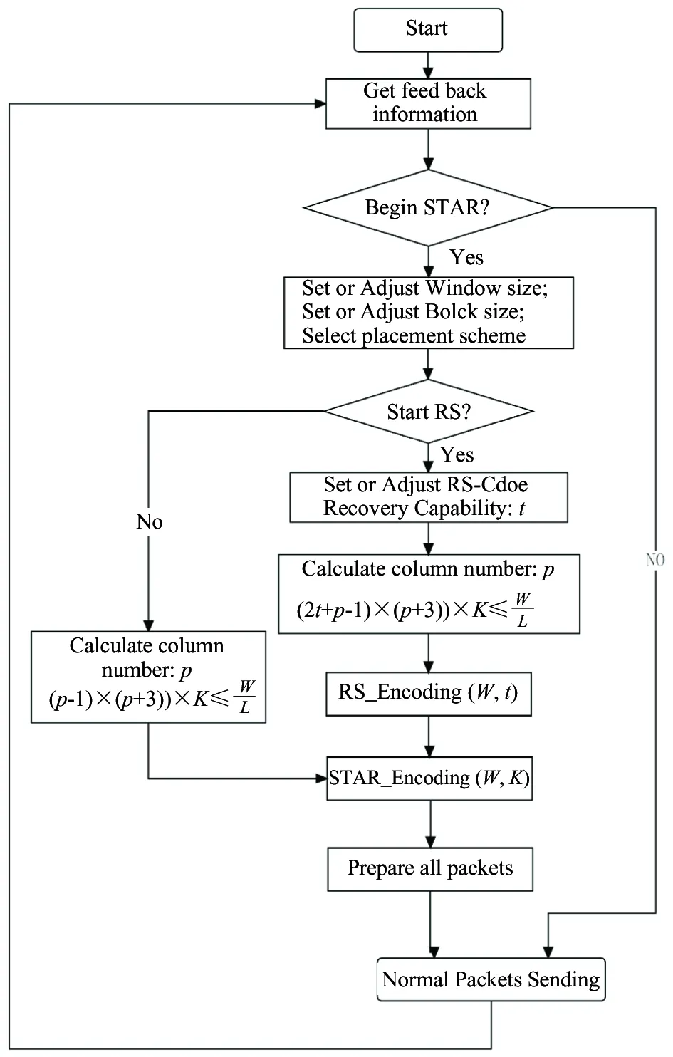
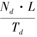
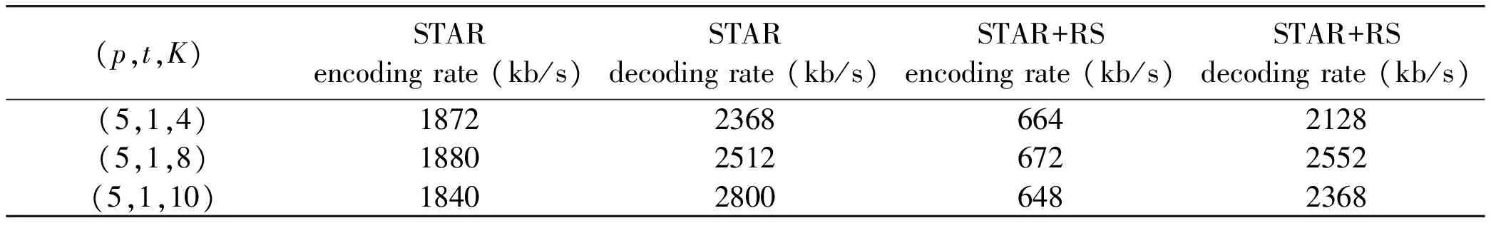
Problem definition: Considering an m×n array, p is a prime number, such that symbol aij(0 It is supposed that a packet is the minimum unit which consists of two parts: packet header PH and data payload PL. When the packets are transmitted in the channel, if packet loss occurs, the whole packet will be considered erased. In the header, there is a unique serial number to indicate its sending order. As shown in Fig.1, the STAR code is a (p+3, p) MDS code, consisting of (p+3) columns, where the first p columns contain information data and the last 3 columns contain parity data. Let P(k)denote the minimum data unit, where k∈N and (0 For simplification, it is supposed the length of the header PH is zero and P(k)can be reduced and rewritten as P(k). Let K denote the maximum packet number containing in one packets block B(i, j). Index i denotes the row number of the packet and j denotes the column number. B(i, j)=[P(i, j, 0)P(i, j, 1)P(i, j, 2),…, P(i, j, K)] (1) Fig.1 STAR and RS coding scheme The STAR code array can be represented by B(i, j)as (2) For convenience, let P(i, j, k)=P(i, j, k), then all packets set P can be described as =PD∪PS∪PR∪PSR∪PM (3) PDdenotes the data packets region, PSdenotes the STAR coding parity packets region, PRdenotes the RS coding parity packets region, PMdenotes the imaginary packets region of STAR coding ,and PRSdenotes the RS parity packets region of the STAR coding parity packets. Therefore, the following formulas hold. (4) (5) (6) (7) (8) In this paper, the audio codec used is the international telecommunication union (ITU-T) standard G.729A CS-ACELP codec. Typically, G.729 supports a frame length of 10 ms and provides payload bit rates of 6.4 kb/s (Annex D), 8 kb/s (original, Annex A, and Annex C), and 11.8 kb/s (Annex E). From Ref.[1], it is known that the the maximum duration of the sending window should be less than 250ms. Let W(bitstr) be the count of the original data bits in a sending bitstream bitstr and ω denote the time window of such maximum duration. Let L be the bit count of a data packet. Let K=Count(B(i, j)) be the count of packets in a block B(i, j)that can be assigned by the user.Then, the following is got: W=ω·b (9) W=(p-1)·(p+3)·C(Block(i, j))·L (10) where, ω≤250ms, 0≤i≤p-1, 0≤j≤p+2. From above two equations, the following equation is got which will be used in the sending procedure: ω·b=(p-1)·(p+3)·K·L (11) Four packet placement schemes are defined which determine how the packets are placed by the sender as to adapt to different network environments as shown in Fig.2. Definition: packet placement schemes (1) Block column first: (P′(i, j))⟸(B(i, j)) (2) Block row first: (P′(i, j))⟸(B(j, i)) (3) Column interleave: (P′(i, j, k))⟸(P(i+j·I+I·J·k)) (4) Row interleave: (P′(i, j, k))⟸(P(j+i·J+I·J·k)) where, (0≤k≤K-1) Fig.2 Packets placement scheme This section presents the idea of the proposed packet loss recovery and concealment algorithm. As shown in Fig.3, once the sender realizes that some of the current packets are lost via feedback information, it tries to start the sender-based loss-recovery techniques by using STAR coding. Otherwise, the sender will still handle all packets normally without any redundant coding information. When the sender decides to begin with redundant error mechanism, it firstly configs all parameters including window size W, block size K, etc. Column number p can be then calculated by the formula: (p-1)·(p+3)·K≤W/L,where L denotes the packet length with packet header and data payload. Note that p should be the maximum prime number that satisfies the inequations. If the RS-coding also needs to start, the algorithm will determine capacity t of RS-coding and recalculate the column number p according to (p-1)·(p+3)·K+2·t·K≤W/L. The algorithm will then perform RS encoding procedure and store the generated redundant packets into rows ranging from p to 2·t+p-1. Otherwise, RS-coding step will be skipped and begin STAR coding process directly. Next, the STAR encoding algorithm is initialized according to these given factors and determines the coding scheme. The redundant symbols can be obtained by STAR Encoding procedure and arranged into p, p+1 and p+2 columns correspondingly. Then, all data packets and redundant packets will be sent to the receiver sequentially. Generally, if the network status is not serious, the sender need not start RS-coding recovery mechanism. Moreover, the two erasure coding techniques are independent of each other and can be applied simultaneously. Fig.3 Packets sending procedure As shown in Fig.4, similarly, at the receiving side, each received packet is stored in the same buffer row by row as the sender until the buffer has received the whole array. When the packets are transmitted in the channel, if packet loss has happened, the receiver will label the corresponding packet lost and clear its content. After that, all the packets in the buffer will be sent to the decoding component, and then the decoded packets will be sent to the concealment algorithm and playout. The whole receiving process is as follows. Firstly, the receiver will check the current coding scheme and calculate buffer requirement for packets array. If the data packets are integrity or only the parity packets are lost, the received parity packets will be discarded directly and decoding procedure can also be skipped. Otherwise, the recovery mechanism will be started immediately. The receiver will then check the lost column number and determine whether the lost columns is beyond the error correction capacity or not. If the STAR decoder can handle current lost columns, then the receiver will call STAR Decoding() procedure to recovery the lost data packets. Otherwise, the receiver will check whether RS-coding scheme has also been applied with the data packets. If true, RS Decoding will be performed to each lost column one by one and recover lost data packets. If the lost rows in a column is beyond the RS-coding capacity, then this column will be discarded and continue to next column. Fig.4 Packets recovery and concealment flowchart If the whole RS-coding procedure is executed, the receiver will restart STAR-coding procedure to recover the handled data packets again. If the current status is still greater than the capacity of STAR-coding, the lost data packets will be cleared and the final stream will be shorten correspondingly. Otherwise, STAR Decoding procedure will be carried on the data packets handled by RS-coding algorithm to recover lost data packets. Next, the new generated stream will be passed to WSOLA algorithm to perform concealment operation and prepared for playout. The time scale factor can be determined by calculating the rate of received stream length and source stream length. In this section, the effectiveness of erasure coding and the end audio quality under various network conditions characterized by packet loss models, packet loss rates, burst loss lengths, and transmission delays is measured. The results show that the performance can be enhanced by applying the proposed method. The sender-based loss-recovery techniques have different levels of performance that are heavily sensitive to the packets-loss properties of the network. The IP network is an interconnection of packet switched data communication networks, composed of hybrid of various wire-line and wire-less transmission links, as well as satellite links. Packet loss may occur due to buffer overflow within the network, deliberate discard as a result of some congestion control policy or transmission errors. Several of the mechanisms that can lead to packet loss are of a transient nature and hence the resulting packet loss is bursty in nature. In this paper, three packet-loss models will be considered which are random loss model, burst loss model and Gilbert loss model. (1) Gilbert loss model In this paper, the 2-state Gilbert model[11]is considered to characterize the bursty channel behavior. This model is widely used for describing error patterns in transmission channels and for analyzing the efficiency of coding for packets losing and recovery. Bolot[12]also studied the distribution of packet loss in the Internet and concluded that this could be represented by a Gilbert or Elliott model. As shown in Fig.5, the usual notation of a good (G) and bad (B) state is shown. Each of them may generate errors as independent events at a state dependent error rate 1-g in the good and 1-h in the bad state, respectively. When the channel is in the good state, there are very few packet losses, whereas when the channel is in the bad state, many packets are lost. Fig.5 Gilbert loss model Packet losses in the bad and good states are independent and occur with rates λ and γ respectively. (2) Random loss model With random loss model packets are lost randomly. If packet loss is entirely independent from one instant to the next, random loss would be experienced. Random loss is a condition that is very favorable for many of the sender-based loss-recovery techniques due to the relatively rare occurrences of multiple consecutive lost packets with random loss. The probability of losing m consecutive packets in a random-loss scenario drops sharply as m increases. M is used which is in Eq.(12) to represent the random loss packet location M=rand(ε) 0<ε (12) (3) Simple burst loss model In burst loss scenario, if the current packet is lost, the next packet is also likely to be lost. For burst loss model it is assumed that a condition that causes the loss of a packet persists for some period of time and therefore causes us to lose one or more subsequent consecutive packets. In order to study the effects of bursts of lost packets and erasure coding scheme on audio quality, the simulator is programmed to simulate burst loss by discarding lost packets in group of random sizes. As shown Fig.6, there are three parameters to control the packet dropping process, which are bc-burst count bl-burst length of each time bt-burst time Fig.6 Burst loss model The burst packets losing rate PLR can be defined as (13) bti+bli·1≤bti+1 (14) btbc-1+blbc-1≤W (15) In fact, the data packets will experience different delays when they are transmitted from the sender to the receiver over IP network. The inter-arrival time of the packets on the receiver will not be constant even though the packet inter departure time on the sender is constant, which results in a jitter that packets arrive at the destination with varying delays between packets. In the simulator, this factor is not considered. Firstly, necessary variables and symbols are defined and summarized for evaluating the algorithm performance as follows. p-a prime number, total number of column in STAR-coding; t-number of rows, the capacity of RS-coding recovery; l-size of codeword in code (Reed Solomon code); L-number of bits of a packet (packet size); ω- time window size(ms); W-window size(bits); F-frame length (ms); PLR-packet loss rate(random, burst, Gilbert); α-time scaling factor(WSOLA); ρE-error rate of Gilbert Model; b-payload bit rates of audio sources(kbps); γ-state transition probability to change from the good state to the bad; λ-state transition probability to change from the bad state to the good; Te-source data packets encoding time; Ne-number of source data packets for encoding; Nd-number of received data packets for decoding; As shown in Fig.7, the simulation and test experiment process are described. In the sender, the original audio clips are taken from the public speech database. The internet communication environment is simulated by the simulator with three impairment profiles: random, burst and Gilbert loss models. To evaluate the approach comprehensively, two categories of testing experiments are provided: Pure performance tests: performance indexes and MOS rating[13]under various conditions of the algorithm. Comparison tests: audio quality comparison between plain delivery of G.729 and the array coding based enhancement approach. G.729[14]is selected in the experiment because it is an International Telecommunications Union standardized low bit-rate codec providing near toll quality. Generally, G.729 is a kind of code-excited linear prediction (CELP) codec and runs at 8 kbps with a 10 ms frame. Furthermore, a plain delivery approach is taken as a baseline for the purpose of comparison with the optimized techniques. Plain delivery is more prevalent than any other delivery technique in VoIP solutions which does not provide any sender-based effort to improve audio quality when packets loss occurs. Fig.7 Simulation process The involved pure performance indexes of algorithm are listed as below. MOS rating: audio quality result, in terms of the mean opinion score (MOS), which ranges from 1 (worst) to 5 (best). Encoding rate: encoding packets number per second with RS-coding or STAR coding. Decoding rate: decoding packets number per second with RS-coding or STAR coding. (1) Experiment under random loss model Fig.8 presents the MOS ratings with 5, 10, 15, 20, 25, and 30 percent packet loss at random loss. (2) Experiment under Gilbert loss model Fig.9 presents the 5, 10, 15, 20, 25, and 30 percent packet loss at Gilbert loss. Fig.8 Experiment results under random loss model (3) Experiment under burst loss model Fig.10 presents the MOS ratings with 5, 10, 15, 20, 25, and 30 percent packet loss at burst model. The study indicates that STAR coding or STAR+RS coding frequently achieves a higher MOS rating than G.729A in various consecutive-loss tests. Fig.8~Fig.10(a),(b),(c) are the results of only the sender-based packet loss recovery , the recovery are STAR、STAR+RS and STAR+RS+PRS, and the Fig.8~Fig.10(d),(e),(f) are the results of sender-based packet loss recovery and receiver-based packet concealment, the packet concealment is WSOLA. It is seen that under the random loss model , the STAR coding achieves the best performance among the STAR coding , STAR+RS coding and STAR+RS+PRScoding. From Fig.8(a), it can be seen that if audio codec G.729 and after STAR redundant coding are selected, it can achieve better MOS score than onlyG.729 at all packet loss rate. If receiver exploits the WSOLA, from Fig.8(d), (e) and (f), it can be seen that the performance of STAR+WSOLA can achieve better performance than only G.729+WSOLA. Fig.9 shows that the results of Gilbert loss model are similar to those of random loss model. Fig.9 Experiment results under Gilbert loss model Fig.10 Experiment results under burst loss model Fig.10 is the results of burst loss model, from Fig. 10 (a), (b) and (c), it can be seen that the performance of STAR and STAR+RS are similar, they all can achieve higher MOS rating of all packet loss rate than only G.729. When receiver exploits the WSOLA, Fig. 10 (d), (e) and (f) show that if the packet loss is more than 15%, G.729+STAR+WSOLA and G.729+STAR+RS+WSOLA all can achieve higher score than only G.729+WSOLA, but if packet loss is too high, the results will be worse. Due to special properties of array codes, the encoding and decoding procedure are performed with pure XOR and shift operation. The performance of the method is shown in Table 1. Table 1 Performance of encoding and decoding From Table 1 it can be seen that the rate of STAR coding is faster than STAR+RS coding because of the computational complexity of RS coding. And the decoding rate is little difference. So the delay of STAR coding is smaller than the STAR+RS coding. An efficient QoS enhancement mechanism based on array code for lost packets recovery is proposed. The experimental results have shown that the method has low computational complexity and lower delay which proves that the array coding in VoIP system has a good effect on packet loss recovery, and is suitable for real-time applications. This method is suitable for random packet loss model, the Gilbert packet loss model and the burst packet loss model. In the following studies, the proposed method will be applied to more complex models to test its performance under new environment, and make it widely use in the VoIP system in the future. [ 1] Brady P T. Effects of transmission delay on conversational behavior on echo-free telephone circuits. Bell Labs Technical Journal, 1971, 50(1):115-134 [ 2] MacWilliams F J, Sloane N J A. The Theory of Error Correcting Codes. Amsterdam: North-Holland, 1977. 11-33 [ 3] Jin H, Cortes T, Buyya R. High Performance Mass Storage and Parallel I/O. New Jersey/New York: John Wiley & Sons, 2001. 187-208 [ 4] Xu L, Bohossian V, Bruck J, et al. Low-density MDS codes and factors of complete graphs. IEEE Transactions on Information Theory, 1999,45(6):1817-1826 [ 5] Xu L, Bruck J. X-code: MDS array codes with optimal encoding. IEEE Transactions on Information Theory, 1999,45(1):272-276 [ 6] Blaum M. A family of MDS array codes with minimal number of encoding operations. In: Proceedings of the IEEE International Symposium on Information Theory, Seattle, USA, 2006. 2784-2788 [ 7] Huang C, Xu L. STAR: an efficient coding scheme for correcting triple storage node failures. In: Proceedings of the Usenix Conference on File & Storage Technologies, San Francisco, USA, 2005. 889-901 [ 8] Tamo I, Wang Z, Bruck J. Zigzag codes: MDS array codes with optimal rebuilding. IEEE Transactions on Information Theory, 2015, 59(3):1597-1616 [ 9] Wang Y, Li G, Zhong X. Triple-Star: a coding scheme with optimal encoding complexity for tolerating triple disk failures in RAID. International Journal of Innovative Computing, Information and Control,2012,8(3): 1731-1742 [10] Verhelst W, Roelands M. An overlap-add technique based on waveform similarity (WSOLA) for high quality time-scale modification of speech. IEEE International Conference on Acoustics, 2002,2(2):554-557 [11] Hasslinger G, Hohlfeld O. The Gilbert-Elliott model for packet loss in real time services on the Internet measuring. In: Proceedings of the GI/ITG Conference of Measuring, Modelling and Evaluation of Computer and Communication Systems, Dortmund, Germany, 2008. 1-15 [12] Bolot J, Fosse-Parisis S, Towsley D. Adaptive FEC-based error control for interactive audio in the Internet. In: Proceedings of IEEE Infocom, New York, USA, 1998. 1453-1460 [13] Chua T K, Pheanis D C. QoS Evaluation of Sender-Based Loss-Recovery Techniques for VoIP. IEEE Network , 2006,20(6):14-22 [14] Telecommunication Standardization Sector of ITU. G.729 Coding of Speech at 8 kbit/s Using Conjugate-Structure Algebraic-Code-Excited Linear Prediction. Geneva: International Telecommunication Union.1996 Li Zhen, born in 1978. She received her Master degree in Hebei University of Technology in 2003. She worked in Communication University of China since 2003. Her research interests include the digital signal processor, voice communication and speech enhancement. 10.3772/j.issn.1006-6748.2017.04.007 ①Supported by the National Science and Technology Planning Project (No. 2012BAH38F00). ①To whom correspondence should be addressed. E-mail: lizhen@cuc.edu.cn on Jan. 10, 2017*, Zhang Qin* data packets decoding and recovery time;
2 Overall enhancement algorithm
2.1 Sending procedure
2.2 Receiving procedure

3 Experiment and evaluation
3.1 Packet loss model


3.2 Simulation of packets loss


3.3 Experiment under different models


3.4 Performance evaluation
4 Conclusions and future work
 High Technology Letters2017年4期