
An integral calculation approach for numerical simulation of cavitating flow around a marine propeller behind the ship hull *
2019-01-05 08:09ChengzaoHan韩承灶YunLong龙云BinJi季斌XinpingLong龙新平ZhirongZhang张志荣
水动力学研究与进展 B辑 2018年6期
Cheng-zao Han (韩承灶), Yun Long (龙云), Bin Ji (季斌), Xin-ping Long (龙新平),Zhi-rong Zhang (张志荣)
1. State Key Laboratory of Water Resources and Hydropower Engineering Science, Wuhan University, Wuhan 430072, China
2. School of Power and Mechanical Engineering, Wuhan University, Wuhan 430072, China
3. National Key Laboratory on Ship Vibration and Noise, China Ship Scientif i c Research Center, Wuxi 214082,China
Abstract: In this paper, the unsteady cavitating turbulent flow around a marine propeller is simulated based on the unsteady Reynolds averaged Navier-Stokes (URANS) with emphasis on the hull-propeller interaction by an integral calculation approach, which means the propeller and hull are treated as a whole when the cavitating flow is calculated. The whole calculational domain is split to an inner rotating domain containing a propeller and an outer domain containing a hull. And the two split sections are connected together in ANSYS CFX by using the GGI interfaces and the transient rotor stator frame change/mixing model. The alternate rotation model is employed for the advection term in the momentum equations in order to reduce the numerical error. Comparison of predictions with measurements shows that the propeller thrust coefficient can be predicted satisfactorily. The unsteady cavitating flow around the propeller behind the ship hull wake shows quasi-periodic features including cavity inception, growth and shrinking. These features are effectively reproduced in the simulations which compare well to available experimental data. In addition, significant pressure fluctuations on the ship hull surface induced by the unsteady propeller cavitation are compared with experimental data at monitoring points on the hull surface. The predicted amplitudes of the first components corresponding to the first blade passing frequencies match well with the experimental data. The maximum error between the predictions and the experimental data for the pressure pulsations is around 8%, which is acceptable in most engineering applications.
Key words: Integral calculation approach, cavitating flow, hull-propeller interactions, pressure fluctuations
Cavitation is a major concern that influences propeller performance due to abrasion, vibrations, and noise as a complex unsteady phenomenon. The increasing requirement to improve ship propulsion efficiency and safety is limited by the cavitation effects. The cavitation around the propeller is mainly characterized by sheet cavitation at the leading edge of the blade and by intense tip vortex cavitation. There is, thus, a need both for better cavitation prediction and for improved analytical tools.
Experimental observations can show numerous visual phenomena but suffer from restrictions on measurement flexibility. Thus, the whole flow field CFD models can be a useful supplement to experimental data. There have been numerous numerical simulations of cavitation to obtain deeper understandings of transient cavitating turbulent flow effects.Cheng et al.[1]used a filter-based density correction turbulence model to reveal the interaction between cavitation and vortices. Wu et al.[2]used the -kω SST turbulence model and the Zwart cavitation model to simulate unsteady cavitating flows around a single marine propeller. The periodic cavitation development was well captured and the periodic pressure fluctuations were analyzed. They pointed out that the high sound pressures were focused on the lower-order blade passing frequencies for the non-cavitating case,but in cavitating flows, the sound pressures induced by cavitation was higher in the high frequency stage.The Roe scheme was split into five parts by Li and Li[3]and they investigated the role of these parts in the turbulence at a low Mach number. They then presented a modified all-speed Roe scheme for the LES method that calculated well even with a coarse grid.Long et al.[4]used the LES method to model an unsteady cavitating flow with the Euler–Lagrangian coupling investigation to analyze the relationship between the cavitation and the vortices. Their results indicated that cavitation promoted the vortex generation and flow instabilities. Lu et al.[5]simulated cavitating flow around two propellers mounted on the end of a tilted shaft in open water. Their simulated results, supported by experiments, showed that LES was able to correctly capture the cavitation development with very good wall resolution needed to correctly capture the cavitation details on the blade.Rhee[6]used a cavitation model coupled with a single-fluid multi-phase flow method to predict cavitating flow around a single propeller in open water. They accurately predicted the hydrodynamic performance of the marine propeller for the noncavitating case. For the cavitating case, comparisons with measured data showed that the method captured many details of the cavitating flows such as the cavitation inception and the cavity shape over the blade. Ji et al.[7]used the partially-averaged Navier-Stokes (PANS) computational model to predict the cavitating flow around a propeller without a hull in a non-uniform wake. The PANS method predicted the fluctuations of the large cavity volume as the blade moved through the wake field better than RANS models using the -kε and -kω SST turbulence models. They confirmed that the whole cavitating flow development process around the propeller could be well reproduced by the PANS method. Di Mascio et al.[8]used detached eddy simulations (DES) to study the wake instabilities around a marine propeller in an oblique flow and purely axisymmetric flow for different loading conditions. They pointed out that the roles of the secondary vorticity which was along the streamwise direction and the hub vortex were crucial in oblique flow. However, they neglected the interaction between the ship and the propeller. Ji et al.[9]simulated the open water characteristics of a marine propeller without considering the hullpropeller interactions. They used a mass transfer cavitation model and the -kω SST turbulence model to predict the thrust and torque coefficients as well as the pressure fluctuations for a highly skewed marine propeller. The predicted hydrodynamic performance agreed well with experimental results and the dominant components of the pressure fluctuation amplitudes were satisfactorily predicted.However, all these studies treated an isolated propeller without the effect of the hull with the complex hull-propeller interactions simplified to a propeller operating with a non-uniform inlet velocity.
This study used an integral calculation approach to calculate the propeller and hull together. URANS is employed to model the cavitating flow field around a model propeller with emphasis on the hull-propeller interactions. For both the steady non-cavitating and unsteady cavitating calculations, the turbulent flows were calculated by using the -kω SST turbulence model and the Zwart cavitation model with the whole grid containing a propeller and a hull. This letter compares the predictions with experimental data with a detailed analysis of the variations ofTK , the pressure fluctuations and the cavity evolution around the propeller behind the hull.
The marine propeller was based on experiments at the China Ship Scientific Research Center (CSSRC)with the propeller mounted on the stern of a ship located in a large cavitation channel. The propeller diameter at the blade tip,mD, was 252.63 mm, the design waterline length,WLL , was 9 m, and the width B was about 1.35 m.
The unsteady turbulent flow simulations around the marine propeller behind a hull used a computational domain including the full flow passage with a propeller and a hull as shown in Fig. 1. The domain inlet was locatedWL1L upstream of the bow with the outlet locatedWL2L downstream of the stern. Along the -Z axis direction, the distance between the ship surface and the computational domain side surface wasWL1L . The whole calculation domain was divided into two parts to simplify the mesh generation.

Fig. 1 Boundary conditions and computational domain
The calculational grid was composed of all hexahedra as shown in Fig. 2. The inner field 1in diameter was a rotating field containing the7propeller.The computational grid with about 1.33×10 cells was well refined in the inner domain which would include the unsteady flow and the cavitation. The outer domain was a rectangular static domain including the hull whose grid had about 1.52×10⁷cells. The two split sections of the computational domain were connected together in ANSYS CFX by using the GGI interfaces and the transient rotor stator frame change/mixing model. The mesh around propeller was quite dense while the mesh further away was sparser to improve the prediction accuracy while reducing the computational resources. The mesh transition from the dense zone to the sparse is fairly soothing. The final grid had about 2.85×10⁷cells. The interactions between the propeller and the hull were well predicted by the high-quality hexahedral grid containing the whole propeller and hull. Besides, it should be noted that the alternate rotation model was employed for the advection term in the momentum equations in order to reduce the numerical error.
The boundary conditions for the cavitating flow simulation has a uniform inlet velocity of =U 6.5 m/s at the domain inlet with the pressure at the domain outlet defined to coincide with the experimental conditions of a cavitation number0.3397. The Reynolds number based on velocity at inlet and chord at 70% span was held at 1.39×10⁶. The propeller rotational speed n is 28 resolutions per second. The no slip wall conditions were applied on the blade surface, the hub and the hull surface. The bottom surface and the side surfaces of the computational domain were all regarded as free slip walls with the free liquid surface set as a symmetry plane.
In the case of unsteady simulation, 5° per timestep was selected for the first ten revolutions, and then 1° per time-step was set for the next ten revolutions.The residual convergence criterion for the calculation was set as 10-3with the maximal 40 inner iterations.

Fig. 2 Outline of the mesh for the hull surface and a partial view of the mesh around the stern and the bow
The accuracy of the unsteady simulation and the hull-propeller interaction were validated based on the cavitation patterns predicted using the whole grid containing the propeller and the hull. The predicted time-dependent cavitation patterns as the propeller rotates are compared with the experimental observations in Fig. 3, where the top row shows the experimental results and the bottom row shows the predictions. The cavitation patterns are visualized by an iso-surface of=1. The figure displays five snapshots for blade position angles from -10°-50° from vertical. As the propeller approaches the hull wake region, the cavity begins to grow from the blade leading edge. Then, a sheet cavity grows across a large span and develops downstream as the propeller rotates into the wake region. Then, the cavity begins to shrink towards the blade tip as the blade leaves the wake and the tip vortex cavity grows downstream.Thus, the simulation can accurately capture the unsteady cavitation patterns and their development around the propeller is well reproduced. The results show how the cavitation evolution on the propeller is affected by the ship hull wake. Thus, the whole region containing the propeller and the hull has to be modeled to reasonably show the interactions between the hull and the propeller.
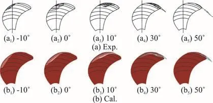
Fig. 3 (Color online) Comparison of the experimental and calculated cavitation patterns during propeller rotation with the angle measured from vertical
The predicted and measured thrust coefficients,, and the error listed in Table 1 agree quite well.

Table 1 Predicted and measured thrust coefficients

Fig. 4 Pressure monitoring points on the hull
The distribution of the monitoring points on the hull surface is shown in Fig. 4. The predicted and measured first blade passing frequencies of the pressure pulsations at these monitoring points are then shown in Fig. 5. Since the monitoring points are at the cavitation locations, the pressure fluctuations on the hull are due to the propeller cavitation. The predicted and measured pressure fluctuations agree well which validates the simulation accuracy. The maximum difference in the first blade passing frequency between the predictions and the measurements is 8%, which is acceptable in most engineering applications. Thus, the results validate the reliability of the simulations and illustrate how the hull-propeller interactions affect the cavitation and the pressure fluctuation.

Fig. 5 Calculated and experimental first blade frequency components of the pressure fluctuations at monitoring points P1-P3
This analysis used the -kω SST turbulence model with the Zwart cavitation model to predict the unsteady turbulent cavitating flow around a marine propeller behind a hull. The model included the hull-propeller interactions with the propeller and the hull modeled together to predict the cavitating flow.The experi- mentally observed cavitation patterns, the thrust coefficient as well as the pressure fluctuations are well predicted by integral calculation approach.The main conclusions are:
(1) The transient cavitating turbulent flow and the cavity patterns on the marine propeller affected by the ship hull wake are satisfactorily predicted, including cavity inception, growth and shrinking induced by the non-uniform hull wake. The predicted cavitation patterns and evolution agree well with the experiments.
(2) The prediction accuracy was evaluated based on comparisons of the predicted thrust coefficients and pressure fluctuations with available experimental results. The results show that the pressure fluctuations at various monitoring points impacted by the cavitating flow agree fairly well with the experimental data.Thus, the present method that models the propeller and the hull together can be used to reliably predict the pressure fluctuations.
More work is needed to reliably simulate the cavitating flow around a marine propeller behind a hull due to the very complex flow structure when treating the propeller and the hull as one system.Verification and validation (V&V)[10]is a systematic methodology used to assess the accuracy of numerical simulations. Thus, V&V will be used to estimate the reliability of numerical results when simulating complex flows. The grid independence of the results must also be included with V&V. Our future work will include a V&V study of the complex cavitating flow around a propeller and hull system. In addition, more analysis methods are needed to further understand the complex cavitating flow around a propeller behind the hull, such as the cavitation-vortex interactions[11-12].Our future work will also focus on studying the cavitating flow around a marine propeller behind the hull with the free surface of ship.
猜你喜欢
幼儿园(2021年18期)2021-12-06
幼儿园(2021年16期)2021-12-06
金秋(2021年22期)2021-03-10
创造(2020年6期)2020-11-20
幼儿园(2020年3期)2020-03-27
读报参考(2019年9期)2019-09-10
新疆艺术(2019年3期)2019-07-17
水动力学研究与进展 B辑(2018年3期)2018-07-06
水动力学研究与进展 B辑(2018年2期)2018-05-14
文史博览·文史(2018年1期)2018-03-12

- 水动力学研究与进展 B辑的其它文章
- Call For Papers The 3rd International Symposium of Cavitation and Multiphase Flow
- Bubble dynamics and its applications *
- Experimental investigation of flow past a circular cylinder with hydrophobic coating *
- Transient peristaltic diffusion of nanofluids: A model of micropumps in medical engineering *
- High-speed experimental photography of collapsing cavitation bubble between a spherical particle and a rigid wall *
- Flow induced structural vibration and sound radiation of a hydrofoil with a cavity *