
Improvement of Flat Surfaces Quality of Aluminum Alloy 6061-O By A Proposed Trajectory of Ball Burnishing Tool
2019-11-26 06:46RubaAlghazoulAlmohanadMakkiandMagdAbdelWahab
Computers Materials&Continua 2019年11期
Ruba Alghazoul,Almohanad Makki and Magd Abdel Wahab
Abstract:Burnishing is a profitable process of surface finishing due to its ability to be automated,which makes burnishing method more desirable than other finishing methods.To obtain high surface finish,non-stop operation is required for CNC machine and we can attain that by choosing a suitable trajectory of the finishing tool.In other words,burnishing paths should be multidirectional rather than monotonic,in order to cover uniformly the surface.Indeed,the burnishing force is also a key parameter of the burnishing process because it determines the degree of plastic deformation,and that makes determining the optimum burnishing force an essential step of the burnishing process a success.Therefore,we consider the strategy of ball burnishing path and the burnishing force as variable parameters in this study.In this paper,we propose a new strategy of burnishing tool path with trochoid cycles that achieves a multidirectional burnishing of the surface according to various patterns.Taking into consideration the optimum burnishing force,to improve flat surface finish of AL6061-O samples by reducing the surface roughness parameter (Rz).Experiments carried out on 3-axis milling machine show that the proposed trochoidal path is more effective than the conventional one.
Keywords:Ball burnishing,surface quality,trajectories,roughness.
1 Introduction
In the competitive world with growing population,the consumer’s requirements have a vital influence on the manufacturer to create high quality products in order to satisfy customer’s expectations.Recently,the traditional machining processes such as drilling,milling,turning,and joining processes have been applied in manufacturing various types of products,which are required in many fields.These machines have been operated and controlled manually by human to turn shaft controller,adjust the feed rate,and turn the coolant.For safety purposes,the operator is asked to understand the main principles of operation before performing any manufacturing activities.The skilled operator is vital to minimize the resources and the reproduced parts.This has led to an alternative machining process called computerized numerical control (CNC)technology,which has been applied in all industries for fast production processes.Great variety of products,such as dyeing automotive body panels and turbine blades rely on special technology to achieve complex forms at tight tolerances.In complex cases,machining these surfaces involves more than 10 000 tool movements and may require a week of continuous machining.Sculptured surfaces are generally machined on multi-axis machines using ball-end milling tools,to be polished later on when mirror-like finish is necessary.The final finishing and hand polishing represent,as much as,75% of the total machining time[Rodríguez,Lopez de Lacalle,Celaya et al.(2011)].
Therefore,burnishing process offers an attractive post-machining stage due to its cheapness,and its relatively simple operation to generate high quality finish.Burnishing is an effective method to improve the surface finish and can be carried out using existing machines,such as lathe and milling machines.In addition to high productivity,burnishing offers low cost comparing with other conventional processes,such as super finishing,honing and grinding [Mahajan and Tajane (2013)].The burnishing process gives many advantages in comparison with chip-removal processes [Hasan,Al-Jalil and Ebied (1998)].Sometimes,burnishing is the only method in which the technical requirements can be satisfied,for example some classes of high surface finish (Rz of 0.2µm-0.8 µm)on untreated steels,copper and aluminum alloys can be achieved with considerable work hardening [Loh and Tam (1988)].
To obtain the best surface finish,the optimum principal process parameters must be ascertained.The most important parameter is burnishing force,which determines the degree of plastic deformation.The other parameters are:feed-rate,ball material and diameter,lubrication,work piece material,burnishing speed,number of burnishing passes,and pre-machined surface roughness [Loh and Tam (1988)].In the recent years,many investigations have been carried out to find the optimal parameters of the ballburnishing process.Dabeer and Purohit investigated the optimization of ball burnishing parameters namely burnishing speed,burnishing force,number of burnishing passes,and feed,on a lathe [Dabeer and Purohit (2013)].Manole and Nagi studied the feed rate influence on burnishing degree in ceramic ball burnishing process on a lath [Manole and Nagi (2011)].Sagbas investigated the optimization of ball burnishing process of 7178 aluminum alloy [Sagbas (2011)],in which burnishing force,number of passes,feed rate and burnishing speed were considered as studied variables.Lopez de Lacalle et al.Studied the effects of two groups of parameters:a)the ball-milling conditions and b)the burnishing force [Lopez de Lacalle,Lamikiz,Sanchez et al.(2007)].Ibrahim presented an investigation into the effect of burnishing parameters namely burnishing feed,burnishing speed,and burnishing force upon final surface texture,roughness and roundness,on a lathe [Ibrahim (2008)].Lopez de Lacalle et al.studied the use of the ball burnishing process to improve the final quality of tools form,moulds and dyes [Lopez de Lacalle,Lamikiz,Munoa et al.(2005)].Shiou and Chen determined the optimal plane ball-burnishing parameters for plastic injection moulding steel PDS5 on a machining centre [Shiou and Chen (2003);Shiou and Chen (2003)].The aim of their study was to determine the optimal plane parameters,i.e.,ball material,burnishing speed,burnishing force,and feed,and to apply the optimal conditions on freeform surface.Takada and Sasahara examined the effect of burnishing tool tip radius on surface roughness,hardness,and residual stress [Takada and Sasahara (2018)].Uddin et al.presented a comprehensive investigation into deep ball-burnishing of a biodegradable AZ31B Mg alloy,in order to improve the alloy’s surface integrity [Uddin,Hall,Hooper et al.(2018)].A series of experiments using an in-house built burnishing tool with a 10-mm steel ball have been conducted,with a key focus of exploring the influence of the major process parameters,e.g.,burnishing force (750-2650 N),feed rate (150-500 mm/min),and step-over (0.05-0.15 mm),on hardness and finish quality.Hiegemannand Tekkayainvestigated the influence of burnishing tool concept on the processing time as well as on the leveling of surface irregularities [Hiegemannand Tekkaya(2017)].
Other studies used modeling and computer methods to predict the quality of the surface by burnishing process.Loriya and Patel dealt with finite element analysis of burnishing process on aluminum alloy 6061 T6 and the input parameters were speed,feed,and force[Loriya and Patel (2018)].While,the output parameter was surface roughness and the results showed that burnishing is an economical and feasible mechanical treatment for the quality improvement of roughness surface.Hamdouni et al.performed a mathematical modeling of the average roughness Ra and the surface hardness of the treated surfaces by the response surface methodology [Hamdouni,Bouzaiene,Montagne et al.(2016)].Furthermore,the use of adaptive finite element techniques,e.g.,Nguyen-Xuan et al.[Nguyen-Xuan,Liu,Bordas et al.(2013)] and Chau et al.[Chau,Ngo,Hackl et al.(2018)],seems to be promising for this type of application.
The above brief review of the literature shows that ball burnishing technique can be easily applied in the same machining centers as those used for milling.In this way,both lead times and production costs can be dramatically reduced comparing with other traditional methods.Besides,burnishing process with end-ball tool has the advantage of finishing either plane or freeform surface,which is not available in burnishing with endroller tool.Literature survey also shows that the roughness term was unexplained and mysterious in most studies as we can distinguish two types of roughness term after burnishing as shown in Fig.1.
There are two types of roughness term as follows:
• The first one refers to the roughness resulted by the longitudinal movement of the burnishing tool.This term of roughness can be used as a criterion of surface quality improvement.
• The second one refers to the roughness resulted by the transverse movement of the burnishing tool.This term of roughness can be used as a criterion of burnishing trajectory effect,and can be determined from Fig.1 as:
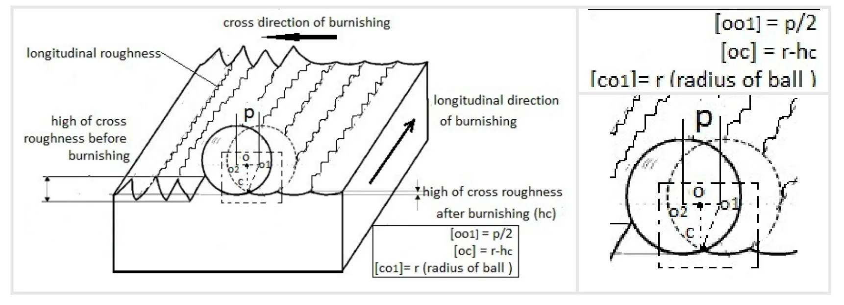
Figure1:A schematic diagram of the longitudinal and transverse roughness
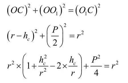
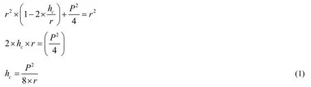
Eq.(1)shows that transverse roughness is related to the transverse pitch of burnishing (p),which in its turn is affected by ball trajectory.
It is clear from literature that the effect of burnishing force was considered in most studies as an important parameter,but none of these studies investigated the effect of burnishing tool trajectory.In this study,we propose a new strategy of tool trajectory and study its effects.
The following sections in this paper are as follows.Section 1 presents the tool path generation.Section 2 summarizes materials and methods used in the research including the tool and path generation,burnishing design,and the specimens design.Section 3 provides details of the conducted experiments of the ball burnishing using two different trajectories.
And in Section 4,surface roughness measurement of the tested specimens and analysis and discussion of the results are presented.Finally,concluding remarks are provided.
2 Experimental procedure
2.1 Experimental setup and sample preparation
2.1.1 Tool path generation
Generating conventional burnishing tool paths is usually done by using SURFCAM 2014 R2 software based on 2D/3D CAD model of the studied part,where the G-code program is generated and carried out on CNC 3-axis machine.
The classical burnishing tool paths generated by SURFCAM usually consist of one trajectory called guide trajectory,which is a zig-zag or a spiral line as shown in Fig.2.
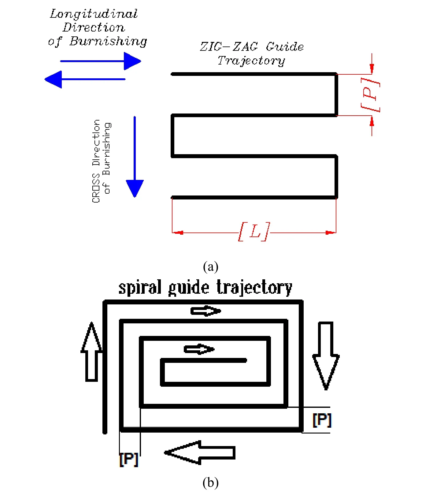
Figure2:A presentation of classical paths:a)zig-zag guide path and b)spiral guide path)
It is noticeable from Fig.2 that the transverse pitch of the classical burnishing paths (zigzag or spiral),which is the space between a pair of guide lines of the path,causes places without burnishing in addition to marks due to the transverse movement of the ball.In other words,in the case of classical path,the transverse movement of the ball acts as transverse roughness,which can be considered as the main disadvantage of these paths.To overcome this disadvantage,a new trajectory of burnishing tool is created to achieve a widespread multidirectional burnishing process of the surface.On the other hand,the effect of zig-zag path on the longitudinal roughness will rationally be positive as this roughness will decrease after burnishing due to the movement of the ball,which compresses the metal existed in the peaks into the valleys.Basically,the innovated path is composed of two imbricate trajectories as shown in Fig.3,the first trajectory is guide path in zig-zag form (Fig.2),while the second is filling path explained as overlapping trochoid cycles as shown in Fig.4.
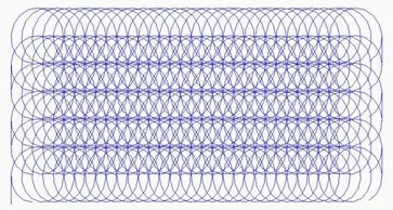
Figure3:Illustration of the new proposed path
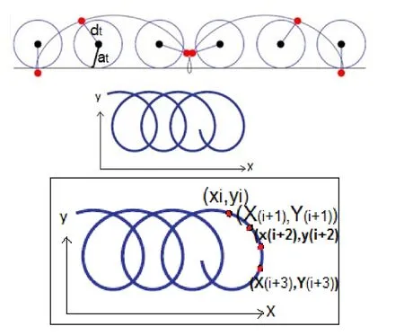
Figure4:Trochoidal filling path
The mathematical expression of trochoid is [Hall (1992)]:

As it can be seen from Fig.4 and Eq.(2)and Eq.(3),the developed burnishing tool path is controlled by three variables as it is composed of two imbricate trajectories.The first variable is the transverse pitch (p),which related to the zig-zag path,and the other variables are (at,dt),which are related to trochoidal trajectory.
The variable (at)is responsible for longitudinal overlap between the cycles of the trochoid,while the variables (dt)and (p)are controlling the transverse overlap between the cycles of the trochoid.Accurate selection of these variables must perform the best path with multidirectional scanning of the burnished surface.To enable of programming CNC machine to execute the proposed trochoidal path,a G-code programs is written using MATLAB as follows:
• Guide and Zig-Zag path is expressed in G-code program based on SURFCAM program.
• Building algorithm Using MATLAB software to perform the filling trochoidal path depending on suitable mathematical equations and the dimensions of the guide path.
• Generating a new G-code using MATLAB to achieve the new path of burnishing process tool,to be used on machine as shown in Fig.5.
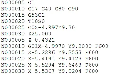
Figure5:A part of G-code program of trochoid
2.1.2 Characteristics of the tools
Our aim is to develop a very simple and profitable way to improve the quality of finished surfaces.Therefore,the burnishing tool is designed to be fastened on milling machine used in machining surfaces,3-axis CNC machine in our study,to reduce time and cost.
The proposed ball burnishing tool consists of many parts namely ball,ball holder,cylindrical casing,spring,tool holder,inner body,and nuts as shown in Fig.6.
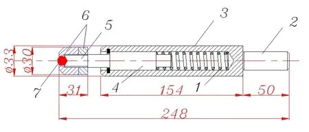
Figure6:The design of ball burnishing tool,(1)spring,(2)tool holder,(3)cylindrical casing,(4)inner body,(5)ball holder,(6)nuts and (7)ball
The suitable value of burnishing force (4 N)for our material was applied by means of a compression spring provided in the tool.The spring rate,which is 11.57 N/mm,is obtained by calculating the slope of the curve representing the relationship between the applied load and the deflection of the spring obtained from a compression test as shown in Fig.7.The ball burnishing tool shown in Fig.8 is manufactured using TOZ-FAGOR CNC lathe,and the ball diameter is 10 mm.
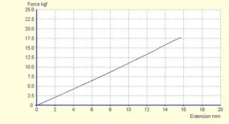
Figure7:Results of compression test on the spring (Force,kgf vs. Deflection,mm)
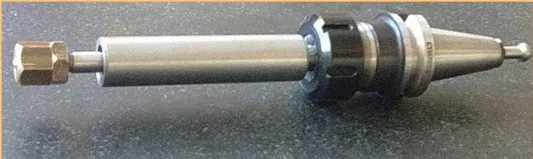
Figure8:Burnishing tool
2.1.3 Design of specimens
Experiments were carried out on specimens surface of aluminum alloy 6061-O,hardness 164 HV.A piece of 310×205×60 mm in size is used as specimen.Surface of specimen had facing milling process by using 3-axis CNC milling machine,Frejoths 2473 with ANILAM 6000 M controller.The conditions of facing process were:end mill tool with 4-carbide with 12 mm diameter,revolution speed 1400 rpm,cut depth 0.5 mm,feed 360 mm/min,and path width 30 mm.The roughness of the surface was measured before burnishing process.The value of roughness parameter Rz before roughness was 1.38 µm in the longitudinal direction and 1.17 µm in the transverse direction.
The surface of the test specimen is divided into zones and each experiment has been applied on a single zone as shown in Fig.9.
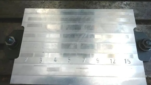
Figure9:Zones of Al-6061 specimen
2.2 Experiments
Burnishing experiments were carried out using a simple tool fixed on the same 3-axis CNC milling machine.The ball burnishing technique is applied on flat surface of Al-606--O.The specimen and burnishing tool are shown in Fig.10.
In our research,the experiments are divided into two groups.In the first group,the optimum burnishing force,which gives the lowest value of surface roughness,is defined by using the conventional path,i.e.,Zig-Zag path.The different values of the used burnishing force are 2,3,4,5,7,9,12 and 15 N.In the second group,the optimum burnishing force,which gives the lowest value of surface roughness,is defined by using the new developed path composed of two imbricate trajectories zig-zag and trochoidal paths.The different values of the used burnishing force are 2,3,4,5,7,9,12 and 15 N.Roughness Rz is measured in two directions,transverse and longitudinal,using roughness tester device.

Figure10:Specimen and burnishing tool fixed on CNC milling machine
2.3 Measurement methods
Practically,the quality of the polished surfaces is first validated by the visual inspection and then by roughness tester (Tip arc radius:10and material is diamond).We use Rz as roughness parameter to test surface quality and compare surface roughness before and after burnishing.The value of roughness parameter Rz before roughness as we have mentioned was 1.38 µm in the longitudinal direction and 1.17 µm in the transverse direction.
3 Results and discussion
Tab.1 shows the results of eight burnishing experiments with zig-zag path with transverse pitch (p=0.2 mm).The time of each experiment was 140 seconds.While,Tab.2 shows the results of eight burnishing experiments with the new path with transverse pitch (p=0.2 mm)and trochoid dimensions (at=0.1 mm,dt=0.7 mm).The time of each experiment was 37 minutes.

Table1:The results of experiments with zig-zag path
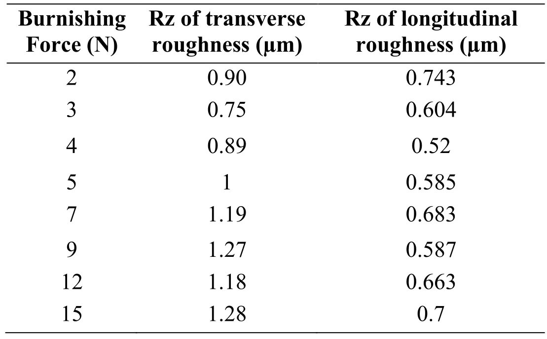
Table2:The results of experiments with the proposed Trochoidal path
As it can be depicted from Tab.1 and Tab.2 the longitudinal roughness of the surface has obviously decreased after burnishing in both cases classic and trochoidal proposed path.This result is reasonable due to the movement of the ball,which leads the metal in the tips of surface topography to fill the valleys,and consequently reduces the height of roughness.The lowest value of Rz is 0.423 µm with burnishing force 5N in the case of zig-zag path,and 0.52 µm with force 4N in the case of the developed path.However,the results of transverse roughness are different between the two paths.In the case of classic zig-zag path,we note that transverse roughness has increased after burnishing (see Fig.2)as the Zig-Zag path consists of repeated guide lines in constant pitch.Zig-Zag method causes unburnished patches between guide lines in addition to prints due to the movement of the ball in transverse direction.
With the new developed trajectory,the transverse roughness has evidently decreased after burnishing as shown in Fig.11 due to the adopted strategy,which includes two trajectories,zig-zag and trochoid.
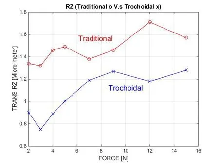
Figure11:Transverse roughness after burnishing with traditional path vs. trochoidal path
This method of planning path gives the advantage to scan the surface in unlimited directions without un-burnished zones and no left stamps.This feature is the main aim of our research.The lowest values of transverse roughness Rz after burnishing using the developed path are 0.75 µm and 0.89 µm with burnishing forces 3N and 4N,respectively.Furthermore,we noticed that there is a fluctuation in surface in in the case of traditional path,because of the marks resulted by the burnishing tool through changing its movement direction.These marks cause random changes in transverse roughness of surface.
The developed path improves the surface quality by reducing the roughness value in all directions in which the value of Rz has decreased by around 36% in the transverse direction and 62.3% in the longitudinal direction that is comparable to the results presented in Shiou et al.[Shiou and Chen (2003);Shiou and Chen (2003)],in which the roughness decreased 62.9%.The zig-zag trajectory reduces the roughness value only in the longitudinal direction of about 69.5% and causes destruction in the surface by increasing the roughness in transverse direction.The disadvantage of our developed path is its longer time comparing with the classical one to achieve the burnishing process.
4 Conclusions
From the presented research work,the following concluding remarks are made:
• We proposed a new strategy of burnishing process based on developing a burnishing tool trajectory consisted of two paths:guide and filling,while the classical one consists of only guide path.
• It was necessary to take into consideration different values of burnishing force due to the importance of this factor.
• We have distinguished two types of roughness,which are transverse and longitudinal,unlike other researches in the literature,where there was ambiguity in the roughness term.
• We have found that the developed path is more effective than the classical one,and it achieves reduction in surface roughness in all directions.
• We have noticed that our proposed path has a disadvantage in the process time of burnishing,where process time increased from 150 (seconds)to (37)minutes.This should be taken into consideration in future work.
• The roughness tester device used in experimental work has left marks on the surface.Therefore,it is important to use non-contact measuring technologies allowing the scanning of the 3D topography of the part and data processing according to the international standard for 3D surface roughness to avoid surface damages.
• Kinematic of the machine used in our experiments does not allow using high burnishing speed,which in turn reduce the process time and roughness.
• We have found that the developed path achieves increasing in surface hardness from 67 HV to 112 HV.
• Our future research aims to investigate the use the ball burnishing tool for burnishing of free-form surfaces,where it is not possible to use the roller burnishing.
 Computers Materials&Continua2019年11期
- Computers Materials&Continua的其它文章
- Efficient Computation Offloading in Mobile Cloud Computing for Video Streaming Over 5G
- Geek Talents:Who are the Top Experts on GitHub and Stack Overflow?
- Implementing the Node Based Smoothed Finite Element Method as User Element in Abaqus for Linear and Nonlinear Elasticity
- Dynamics of the Moving Ring Load Acting in the System“Hollow Cylinder + Surrounding Medium” with Inhomogeneous Initial Stresses
- Human Behavior Classification Using Geometrical Features of Skeleton and Support Vector Machines
- Keyphrase Generation Based on Self-Attention Mechanism