
Design and characteristics of a triplecathode cascade plasma torch for spheroidization of metallic powders
2020-11-10 03:02JierQIU邱吉尔DepingYU余德平YihongLI李裔红LeiLI李磊TongYANG杨彤andYuqingDONG董宇庆
Plasma Science and Technology 2020年11期
关键词:李磊
Jier QIU(邱吉尔),Deping YU(余德平),Yihong LI(李裔红),Lei LI(李磊),Tong YANG(杨彤) and Yuqing DONG(董宇庆)
1 School of Mechanical Engineering,Sichuan University,Chengdu 610065,People’s Republic of China
2 Southwestern Institute of Physics,Chengdu 610041,People’s Republic of China
Abstract
Keywords:triple-cathode cascade plasma torch,plasma jet,plasma spheroidization
1.Introduction
Since the 1950s,arc plasma torches have attracted increasing interest[1],as they can effectively process materials that can hardly be processed by traditional methods[2].As the arc plasma torch has a stable plasma jet,a long service life,a simple design,a low equipment cost and other characteristics[3,4],it has been widely used in material processing,e.g.powder spheroidization,surface spraying,and nanopowder synthesis[5-7].Among them,arc plasma spheroidization can process metallic powders used for 3D printing to meet requirements of narrow particle size distribution(PSD),low oxygen content,high sphericity and flowability[8,9].
Many studies have been carried out on plasma torches used for powder processing.Kumar et al[10]used a 40 kW DC non-transferred plasma spray torch to obtain micro powders.Vilotijevic et al[11]designed a plasma torch with a fixed minimal arc length.Schein et al[12]used a plasma torch that relied on the use of multiple electrodes to improve the stability of the plasma jet.Mauer et al[13]used a TriplexTM,which is a commercially available triple-cathode plasma torch(TCPT),for plasma spraying.The powders were fed at the exit of the nozzle,usually employing three feeding tubes.In these plasma torches,powders were radially inserted into the plasma jet at the nozzle exit(radial injection).Due to the large angle at which the powders are inserted into the plasma jet,it is difficult to adjust the flow rate of the carrier gas of the powders to maintain most powders with different particle size within the plasma jet.If the carrier gas flow rate is small,then small powders will not enter the center of the plasma jet[14].If the carrier gas flow rate is large,then large powders will pass through the plasma jet.These powders staying outside the plasma jet will not be spheroidized.Therefore,it is difficult to achieve high spheroidization ratio for powders with wide PSD by radial injection of powders.
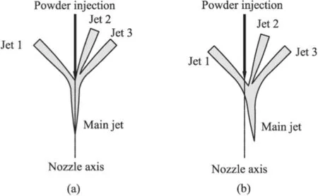
Figure 1.Schematic diagrams of the states of the three plasma jets:(a)equilibrium state,(b)disequilibrium state.
To overcome the above disadvantages of the radial injection,it is desirable to inject powder along the axis of the nozzle or the plasma jet(axial injection).However,this is difficult to achieve for a conventional plasma torch with a single cathode and a single anode due to structural limitations.One way to overcome these structural limitations is to change the single cathode to multiple cathodes.Multiple arcs are formed between each cathode and the common anode,forming multiple plasma jets that then converge at the anode nozzle to form one plasma jet.Figure 1(a)shows that three plasma jets,which are generated from a TCPT,converge to form a main plasma jet.Many studies have been carried out on multiple cathode plasma torches.For example,Young et al[15]designed a TCPT using axial injection.Wang et al[16]designed a multiple cathode plasma torch using axial injection for the deposition of a high-quality coating.Gao et al[17]deposited NiCrAlY coatings using Mettech Axial IIITM,which is one of the commercially available TCPTs.These multiple cathode plasma torches were designed for the preparation of coatings,which emphasizes more on higher velocity of the plasma jet to achieve high adhesion of the coating.As the plasma spheroidization process emphasizes on long residence time of the particles,which means relative low velocity of the plasma jet,if these plasma torches were used in plasma spheroidization,they may present the following disadvantages.Firstly,the working gas flow rate and arc current of plasma spheroidization are different from that of plasma spraying.Under the working parameters of plasma spheroidization,such configuration may be undermined by the large-scale shunting[18]because there are no inter-electrodes between each cathode and the common anode.It will lead to large arc voltage fluctuation and then large fluctuation in the velocity and temperature of the plasma jet,which will inevitability affect the uniformity of the treated powders.Secondly,the arc voltages of these TCPTs are relatively low.To achieve a large power output,the input arc current has to be raised to a large value,leading to rapid erosion of the electrodes because the actual heat flux into electrodes mainly depends on the arc current[19]and thus reduced service life.Thirdly,the gas flow rate of the TCPTs,e.g.Mettech Axial IIITM,is usually very large and the Reynolds numberwhere G is the mass flow rate of the working gas,dais the inner diameter of the anode,andu¯is the mean-mass dynamic viscosity of the working gas at the exit cross-section of the anode)lies within the range of turbulent flow.It means that the plasma jet works in the turbulent state,which is unfavorable for the plasma spheroidization.Fourthly,no attention has been paid to the equilibrium of the multiple plasma jets.When the voltage fluctuations are small and the velocity and temperature of each plasma jet are equal,the main jet remains along the nozzle axis.This state is defined as the equilibrium state.At this state,the properties of the multiple plasma jets were assumed to be the same and the resulting main jet were assumed to be axisymmetric as shown in figure 1(a).However,if the velocity and temperature of plasma jet 1 are larger than that of jet 2 or jet 3 as shown in figure 1(b),the main jet deviates from the nozzle axis and works at a disequilibrium state.At this state,the injected powder will be carried by the main jet to the inner wall of the anode,which may be the main reason of the clogging of the anode.
To overcome these shortcomings,a triple-cathode cascade plasma torch(TCCPT)is presented aiming at the following characteristics.Firstly,the TCCPT can avoid largescale shunting by adopting the cascade design concept to achieve a stable arc voltage.Secondly,the arc voltage of the TCCPT is relatively high.Thirdly,the TCCPT can work at a relatively small gas flow rates to meet the needs of plasma spheroidization.Fourthly,the TCCPT is easier to maintain at the equilibrium state.Fifthly,powders can be axially injected into the TCCPT along the axis of the nozzle so that powders with wide PSD can be processed at the same time.The design of the TCCPT is described in detail in section 2.The characteristics of the TCCPT,including the voltage-current characteristics,the fluctuation of the arc voltage,the equilibrium of the plasma jets and thermal characteristics,were determined by experiments.
2.Design of the TCCPT
A schematic diagram of the designed TCCPT is shown in figure 2(a).Its main components include three cathodes,a common anode,three sets of inter-electrodes,and a powder feeding tube.The cascade design concept using inter-electrodes brings about at least two advantages.Firstly,it avoids the large-scale shunting phenomenon[18].Therefore,the moving range of the arc root is small,resulting in a small arc voltage fluctuation and thus stable temperature and velocity distributions of the plasma jets.In addition,the three plasma jets easily maintain an equilibrium state,which reduces the chance of clogging.Secondly,this design raises the arc voltage(U)of the plasma torch by enlarging the distance between the anode and the cathode.Therefore,for the same output power,the arc current(I)can be greatly reduced,resulting in reduced erosion of the electrodes because the actual heat flux into electrodes mainly depends on the arc current[19]and thus increased service life of the plasma torch.The adoption of the common anode ensures the convergence of the three plasma jets.The adoption of the powder feeding tube(i.e.central injection of powders)ensures that powders with different PSDs can easily be inserted into and stay within the plasma jets.
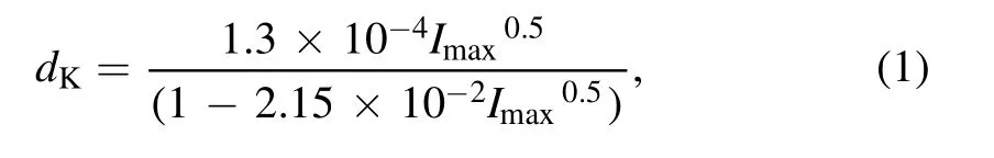
To verify the above advantages,a TCCPT with the design parameters shown in table 1 was designed.The design of the key parameters of the TCCPT,including the interelectrodes,the cathodes,and the anode,will be covered in detail as follows.
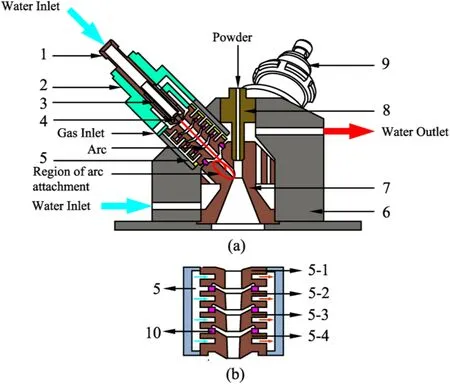
Figure 2.Schematic diagram of the TCCPT:(a)sectional view of the TCCPT:1 Cathode holder,2 Gas injection ring,3 Cathode cooling tube,4 Cathode,5 inter-electrode,6 Anode container,7 Anode,8 Powder feeding tube,9 Cathode assembly;(b)sectional view of an inter-electrode:5-1 Ignition ring,5-2,5-3,5-4 Constriction rings,10 Insulator ring.
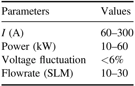
Table 1.The design parameters of the TCCPT.
2.1.The inter-electrodes
Each inter-electrode,as shown in figure 2(b),consists of an ignition ring and three constriction rings.The thickness(d)of each ring should satisfy the requirement ofwhere E is the electric field,VaandVcare the anode and cathode voltage drops,respectively,to avoid the double-arc phenomenon[20],which can seriously damage the inter-electrodes and the anode.These copper rings are electrically separated by insulator rings,which are made of Teflon.The outer diameter and the thickness of each insulator ring are 30 mm and 3 mm,respectively.An ignition ring with an internal diameter of 10 mm is designed to help ignite an arc between each cathode and its inner edges by applying high-frequency and high-voltage pulses to break down the gas in between[21].As shown in figure 2(b),the inner diameter of the constriction ring(5-4)is smaller than that of(5-3),which is smaller than that of(5-2).This design ensures that the plasma jet is constricted as it passes through the constriction rings.

Figure 3.Schematic diagram of the button-shaped cathode.
2.2.The cathodes
Button-shaped cathode as shown in figure 3,which consists of a tungsten disk embedded in copper,was adopted as it can bear higher arc current and shows longer service life compared with the rod-shaped cathode.When argon is used as the working gas,the minimum diameter of the tungsten disk can be calculated by equation(1)[22]
wheredKis the minimum diameter of the cathode andImaxis the maximum arc current.
Based on equation(1),dK=3.59 mm for the maximum arc current of 300 A.Generally,it is recommended to increase this diameter by a factor of 1.2-1.3 to avoid arcing at the junction between the copper and tungsten.Therefore,the diameter of the cathode was chosen to be 5 mm.
2.3.The anode
The anode of the TCCPT,as shown in figure 4,is a common anode shared by the three cathodes.The design parameters of the anode mainly include the angleα1,which is the angle between the projection of two cathodes onto the horizontal plasma,the convergence angleα2,the expansion angleα3,and the channel diametersd1andd2.
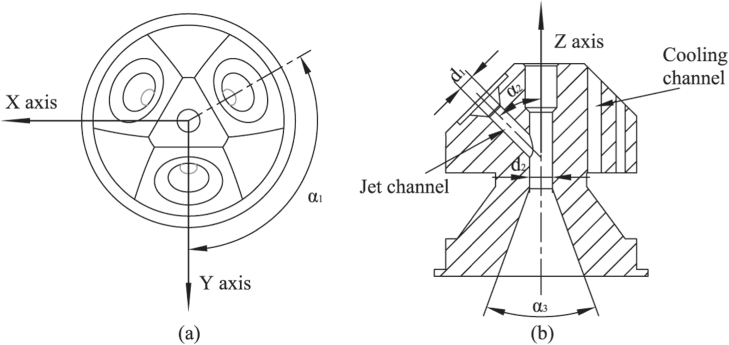
Figure 4.Schematic diagram of the anode:(a)vertical view,(b)sectional view.
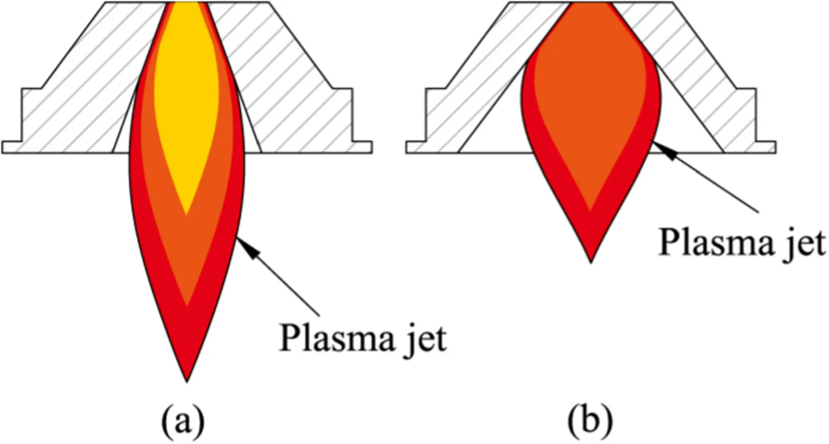
Figure 5.Schematic diagram of the anode with different expansion angles:(a)small expansion angle,(b)large expansion angle.
The convergence angleα2influences the velocity and temperature of the main jet.When the three plasma jets are working in an equilibrium state,the main jet only has a velocity component along the Z axis.When the convergence angleα2is larger,the radial velocity components of the main jet are offset.Therefore,the larger the convergence angleα2,the slower the velocity of the main jet becomes.However,the convergence angleα2also affects the radial component of the heat flux.The larger the convergence angleα2,the larger the radial component of the heat flux becomes,and more energy is taken away from the main jet by the cooling water in the cooling channel,resulting in a decrease in the temperature of the main jet.In contrast,a small convergence angleα2leads to the increase in the velocity and temperature of the main jet.Limited by the size of the powder feeding tube(component 8 shown in figure 2(a))and the cathode assembly(component 9 shown in figure 2(a)),the convergence angleα2was designed to be 45°.
The expansion angleα3determines the velocity and temperature distributions of the main jet at the exit of the anode.Figure 5 schematically shows the state of the main jet for anode with small and large expansion angles.For the anode with small expansion angle shown in figure 5(a),the main jet is compressed to a large degree,resulting in a longer plasma jet with higher energy density.However,as the inner surface of the anode is cold compared with the plasma jet and molten particles,there is a higher risk that the molten particles could be deposited on the inner surface of the anode.For the anode with large expansion angle as shown in figure 5(b),the problem of the particle deposition on the inner surface of the anode can be avoided.In addition,the velocity of the main jet decreases,resulting increased residence time of the powders in the main jet.However,if the expansion angle is too big,the energy density of the main jet may be too low for the melting of the powders.Therefore,the expansion angleα3of the anode nozzle was chosen to be 40°,which was observed from experimental trials to be suitable for plasma spheroidization with minimum particles deposition on the inner surface of the anode.
The channel diameterd1affects the degree of compression of the three plasma jets.The smaller the channel diameterd1is,the higher the degree of compression of the plasma torch.Therefore,a small channel diameterd1leads to a high velocity of the plasma jet,which reduces the heating time of the powder.Therefore,a reasonable design of the nozzle channel diameter is very important for the performance of the plasma torch.In this study,the channel diameterd1was designed to be 7 mm.
The channel diameterd2affects the velocity and temperature of the jet.A small channel diameterd2leads to a high velocity of the main jet.A large channel diameterd2leads to the energy to be more dispersed,which affects the temperature distribution of the jet.According the square of the diameter ratio of thed,1d2was designed to be 12 mm.
The cooling channel,as shown in figure 4(b),in the anode is designed to be on the opposite side of the plasma jet to ensure sufficient cooling of the inner surface of the anode.
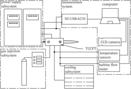
Figure 6.Schematic diagram of a typical TCCPT system.
3.Experimental apparatus and design
3.1.Experimental apparatus
As shown in figure 6,a typical TCCPT system consists of a TCCPT,a cooling subsystem,a gas injection subsystem,and a power supply subsystem.The TCCPT proposed in this paper is shown in figure 7.The cooling subsystem uses a chiller to generate cold water to cool the TCCPT and power source subsystem.The gas injection subsystem uses three mass flow controllers(maximum flow is 30 SLM),to precisely provide the plasma-forming gas to the TCCPT.The power supply subsystem uses 3 sets of insulin gate bipolar transistor(IGBT)power supplies whose conversion efficiency is greater than 90% and fluctuation is less than 1% to power up the TCCPT.
The measurement system of the TCCPT consists of two temperature sensors,a turbine flow meter,a data acquisition module,a CCD camera and a computer.As the cooling water from the cathode sections of the three torches and the common anode as shown in figure 2(a)merge within the torch body and leave through the water outlet,it is impossible to measure their temperatures separately.Thus,two temperature sensors were installed at the main inlet and outlet of the cooling water to measure the main inlet and outlet temperatures.A turbine flow meter was used to measure the flow rate of the cooling water.Given the measured inlet and outlet temperatures and flow rate,the power of thermal loss taken away by the cooling water can be obtained and used to calculate the thermal efficiency of the TCCPT and the enthalpy of the generated plasma jet.The data acquisition module(NI USB-6210,16 inputs,16 bit,250 kS s−1)was used to measure the arc voltage between each cathode and the common anode of the TCCPT at a sampling frequency of 1 kHz.The CCD camera was used to take photos of the three jets to determine the equilibrium state of the TCCPT.The computer was used to control the temperature sensors,the turbine flow meter,the data acquisition module and the CCD camera and to store the data.
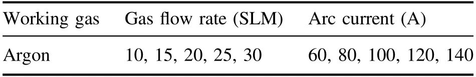
Table 2.Working parameters of the TCCPT.
3.2.Design of experiments
To study the characteristics of the proposed TCCPT,the arc voltage(U)of each torch,the temperature and flow rate of the cooling water were measured with the arc current(I)and the argon flow rate(GAr)set by the control variable method,as shown in table 2.According to the voltage data,the mean and standard deviation of the arc voltage were calculated.Then,the specific enthalpy and thermal efficiency of the TCCPT were calculated by measuring the temperature and flow rate of the cooling water.
4.Results and discussion
4.1.Voltage-current characteristics
As the voltage-current characteristics of the plasma arc of torch 1 is the same as that of the plasma arcs of torch 2 and torch 3.Figure 8 shows the voltage-current characteristics of the plasma arc of torch 1.The arc voltage increases with increasing arc current.The reason may be as follows.As each plasma channel of the TCCPT adopted the cascade design concept as shown in figure 2,the moving range of the arc root on the anode is small,resulting in small variation of the length of the plasma arc at a fixed gas flow rate.Therefore,although the average temperature and thus the electrical conductivity of the plasma arc increase with increasing arc current[23],the growth rate of the arc current is faster than the reduction rate of the resistivity.Therefore,the arc voltage increases with the arc current.
Figure 8 also shows that when the arc current is constant,the arc voltage increases with increasing gas flow rate.The reason may be that increased gas flow rate leads to higher constriction and thus reduced conductivity of the plasma arc[23].In addition,increased gas flow rate leads to longer length of the plasma arc.Reduced conductivity and longer length of the plasma arc mean larger overall resistance,resulting in the increase of the arc voltage.

Figure 8.Voltage-current characteristics of the plasma arc.
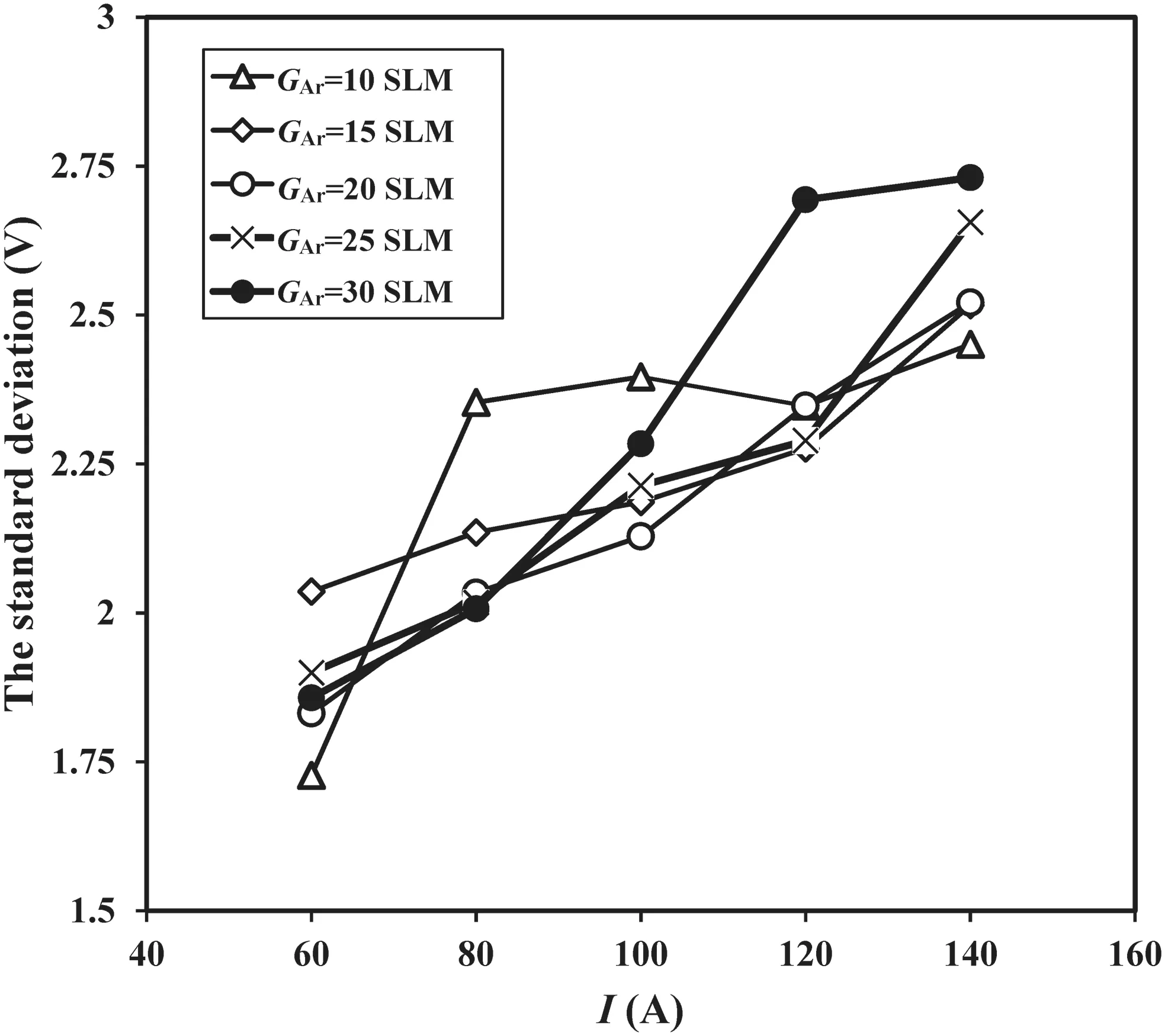
Figure 9.The maximum standard deviations of the arc voltages.
4.2.The fluctuation of the arc voltages
Figure 9 shows the maximum standard deviation of the arc voltage,which is the maximum standard deviation among the three torches.It reflects the fluctuation of the arc voltage in 30 s.When GAr=10 SLM and I=60 A,the maximum standard deviation of the three torches’ arc voltage is 1.74 V.The corresponding original arc voltage signals of the three torches are shown in figures 10(a)-(c),respectively.When GAr=30 SLM and I=140 A,the maximum standard deviation of the three torches’ arc voltage is 2.75 V.The corresponding original arc voltage signals of the three torches are shown in figures 10(d)-(f),respectively.The arc voltage fluctuation is within 5.3%,which is a result of the cascade design of TCCPT that limits the axial moving of the arc root.Therefore,the temperature and velocity of plasma jet are relatively stable during the experiment,which is critical for long time powder processing.
In addition,it can be seen from figure 9 that the arc voltage fluctuation increases with increasing arc current at a fixed gas flow rate.The reason may be that the arc voltage fluctuation was mainly caused by the arc root jumping on the region of arc attachment as shown in figure 2(a).For the TCCPT,the region of arc attachment is small.Therefore,the variation of the resistance of the plasma arc(ΔR)is relatively small.AsΔU=I·ΔR,the arc voltage fluctuation increases with increasing arc current.

Figure 11.The equilibrium index of the three plasma jets.
4.3.The equilibrium of the plasma jets
The equilibrium index(EI)of the three plasma jets,as calculated by equation(2),is proposed to indicate the equilibrium state of the three plasma jets
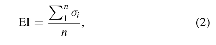
whereσiis the standard deviations of the arc voltages of torch 1,torch 2 and torch 3 at ith sampling instant and n is the total number of samples within 30 s(sampling frequency=1 kHz).
When the EI of the three plasma jets are small,the output power difference among the three plasma torches is small.Therefore,the temperatures and velocities of the plasma jets are expected to be similar.Under these conditions,the TCCPT works in an equilibrium state.The smaller the EI is,the better the equilibrium of the three plasma jets.
Figure 11 shows the EI of the three plasma jets.For a small gas flow rate,i.e.GAr=10,15,20 SLM,the EI almost unchanged.For a large gas flow rate,i.e.GAr=25,30 SLM,the EI increased.The reason for this tendency may be that when the gas flow rate is small,the arcs within the three plasma torches tend to be attached at the small conical section as shown in figure 12(a),resulting in small difference of arc voltages and a relatively small and constant EI.When the gas flow rate is large,the arc attachment leaves the conical section and enters the cylindrical section as shown in figure 12(b).As the region of arc attachment is larger,the arc voltage difference between the three plasma torches is relatively large,resulting in a relatively larger EI.However,as the length of the cylindrical section is small,the maximum EI of the three plasma jets is smaller than 3.5 V,which means that the TCCPT is easy to be maintained at the equilibrium state.At this state,the properties of the three plasma jets were assumed to be the equivalent and the risk of particles deposition on the inner surface of the anode was minimized.
Figure 13 shows photos of the three plasma jets generated at two sets of working parameters.When working parameters was set to I=60 A,GAr=10 SLM,the EI=1.5 V.As shown in figure 13(a),the brightness of the three jets are almost equal.Under this state,the temperatures and velocities of plasma jets are almost equal.When working parameters were set to I=60 A,GAr=30 SLM,the EI=3 V.As shown in figure 13(b),the brightness of jet 1 and jet 2 are larger than that of jet 3.Under this state,the temperatures and velocities of plasma jets 1 and 2 are larger than those of plasma jet 3.The photos of the three plasma jets confirmed that the equilibrium state of the three jets was relatively poor under large EI,which shows that the EI is an effective index to judge the equilibrium state of the plasma torches.
4.4.Thermal characteristics
4.4.1.Thermal efficiency.The thermal efficiency(η)of the proposed TCCPT can be calculated by equation(3)
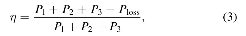
whereP1,P2,andP3represent the input powers of torch 1,torch 2 and torch 3,respectively,andPlossis the power of thermal loss taken away by the cooling water,which can be calculated by equation(4)
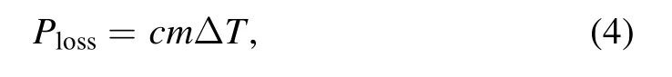
where c,m andΔTare the specific heat,mass flow rate and the temperature difference between inlet and outlet of the cooling water,respectively.
Figure 14(a)shows the thermal efficiency of the TCCPT.The thermal efficiency of the TCCPT increases with increasing gas flow rate at a fixed arc current.The reason for this tendency could be that the arc is more strongly constricted with increasing gas flow rate,leading to the increase of the cold boundary layer and thus reduced the radial heat transfer from the plasma arc to the arc chamber wall.Therefore,as shown in figure 14(b),the power of thermal loss decreases with increasing gas flow rate,which leads to the increased thermal efficiency of the TCCPT.
In addition,the thermal efficiency of the TCCPT decreases with increasing arc current at a fixed gas flow rate.The reason for this tendency may be that with an increase in the arc current,the arc diameter increases,resulting in a decrease of the cold boundary layer.Therefore,the thermal conduction to the arc chamber wall increases,resulting in the decrease of the thermal efficiency.
From figure 14(a),it can be seen that the thermal efficiency of the TCCPT is between 25% and 60%.To achieve a relatively high thermal efficiency,the gas flow rate should be larger than 15 SLM.Under this condition,the thermal efficiency of the TCCPT is larger than 35%.There are two reasons for the relatively low thermal efficiency.(1)The cascade design concept adopted increases the length of the arc channel.In addition,the gas flow rate was relatively small.Therefore,the radial heat conduction from the plasma arc to the arc chamber wall,which is cooled by the cooling water,greatly increased[24].(2)There was an angle between each plasma jet and the anode of the TCCPT.Therefore,the inner surface of the anode was directly impinged by the three plasma jets,leading to high thermal load and thus increased energy loss to the cooling water of the anode.
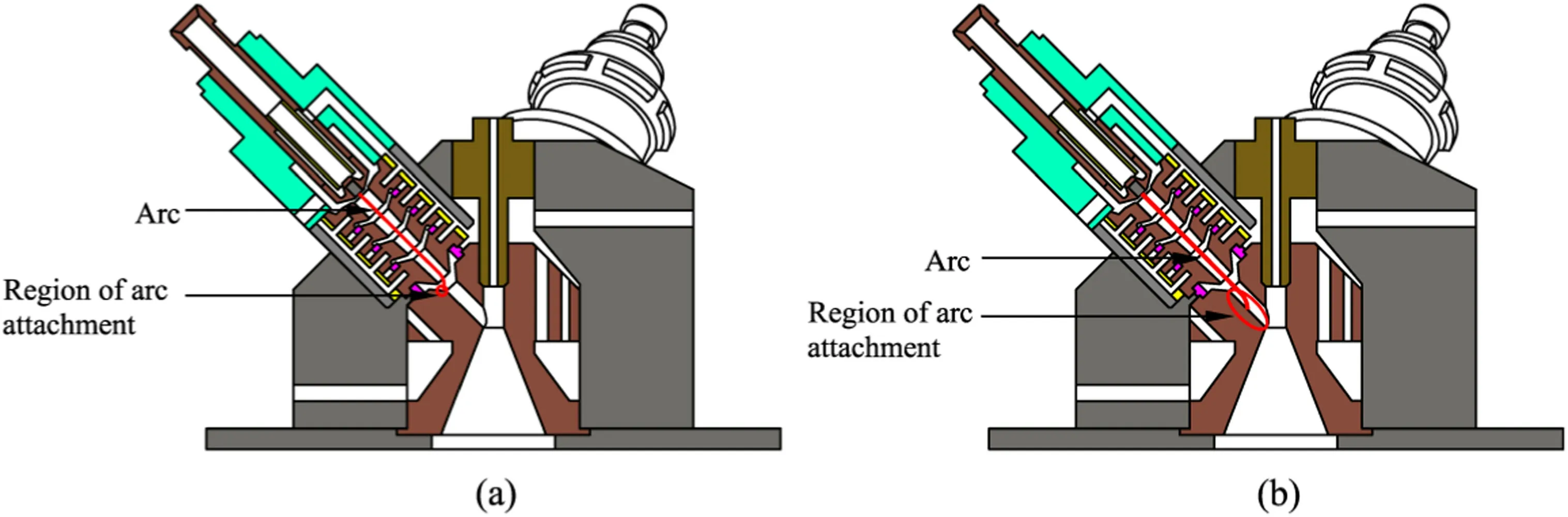
Figure 12.Regions of the arc attachment:(a)small gas flow rate,(b)large gas flow rate.
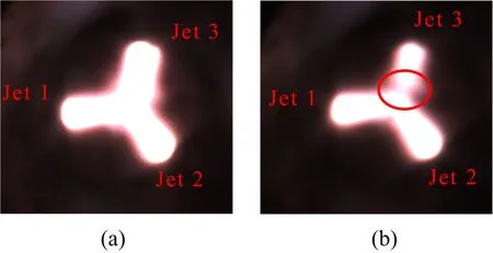
Figure 13.Photos of the three jets:(a)I=60 A,GAr=10 SLM;(b)I=60 A,GAr=30 SLM.
4.4.2.Specific enthalpy.The specific enthalpy(h0)refers to the energy contained in a gram of working gas,including the kinetic energy and the thermal energy.It can be calculated by equation(5)
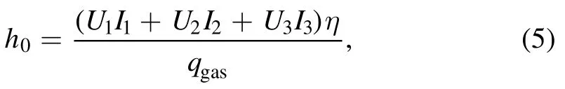
whereU,1U2andU3are the average arc voltages of torches 1,2 and 3,respectively,I,1I2andI3are the arc currents of torches 1,2 and 3,respectively,qgasis the mass flow rate of the working gas.It can be seen that the arc voltage,arc current and gas flow rate determine the specific enthalpy of the plasma jet.
Figure 15 shows the specific enthalpy of the main plasma jet generated by the TCCPT.It ranges between 2 and 11 kJ g−1.For a fixed gas flow rate,the specific enthalpy increases with increasing arc current.The reason for this tendency could arise from equation(5).If the gas flow rate is constant,the arc voltage increases with increasing arc current.Although thermal efficiency(η)slightly decreases,the decrease rate is smaller than the overall increase rate of arc current and arc voltage.For a fixed arc current,the specific enthalpy decreases with increasing gas flow rate.The reason for this tendency is that with an increase in the gas flow rate,the input power and thermal efficiency(η)slightly increases.However,their total increase rate is smaller than that of the gas flow rate,and thus the specific enthalpy decreases with increasing gas flow rate.
During the process of plasma spheroidization,high thermal energy and relatively low kinetic energy of the plasma jet are preferred.As the specific enthalpy contains both the kinetic energy and thermal energy,it directly determines the spheroidization ratio.At a fixed gas flow rate,it can be seen from figure 15 that the specific enthalpy increases with increasing arc current.Thus,it is expected that the spheroidization ratio will increase with increasing arc current.In addition,at a fixed arc current,with the increase of gas flow rate,the specific enthalpy decreases as the thermal energy decreases while the kinetic energy slightly increases.It means that the temperature of the plasma jet decreases with increasing gas flow rate for a fixed arc current[25]and thus the spheroidization ratio is expected to decrease with increasing gas flow rate.Overall,relatively low gas flow rate and high arc current are preferred for the plasma spheroidization process.
4.5.Application of the TCCPT for the spheroidization of powders
To show the effectiveness of the proposed TCCPT for the plasma spheroidization process,the TCCPT was installed on apparatus shown in figure 16 for the spheroidization of SUS304 stainless steel powders.It includes a TCCPT,a powder feeding device,a spheroidization chamber,a cyclone,a pump,a power supply subsystem,a cooling subsystem and a gas injection subsystem.The powder feeding device can control the feeding rate of the powders.Then,the powders were heated,melted,cooled,condensed,and collected in the spheroidization chamber,which was filled with argon to prevent the melted powders from oxidizing.Argon was used as the working gas in both the powder feeding gas and the gas injection subsystem.The cyclone was used to separate mixtures of argon and the powders.The pump was used to draw gas from the chamber to maintain its pressure close to 0.1 MPa.
According to the characteristics of the TCCPT,its working parameters used in the spheroidization experiment was set to I=140 A,GAr=10 SLM,under which the EI of the plasma jets was 2.1 V and the specific enthalpy was 10 kJ g−1.In addition,the SUS304 stainless steel powder feeding rate was set to 25 g min−1.
The powders before and after plasma spheroidization were observed using an optical microscope(Olympus GX51).The observed microscopic images of the raw powders and spheroidized powders are shown in figures 17(a)and(b),respectively.It can be seen that the raw powders are irregularly shaped,while the spheroidized powders are spherical regardless of the particle diameter with the spheroidization ratio close to 100%.The PSDs of the powders before and after plasma spheroidization were measured by a laser particle size analyzer(Mastersizer 3000),with the obtained PSD shown in figure 18.It can be seen that the PSD of powders is wide,ranging from 20 to 350 μm.From figures 17(b)and 18,it can be inferred that the TCCPT is applicable and effective for the spheroidization of powders with wide size distribution.In addition,it can be seen from figure 18 that the PSD of spheroidized powders is close to that of the raw powders,meaning that the plasma spheroidization has little effect on the PSD.
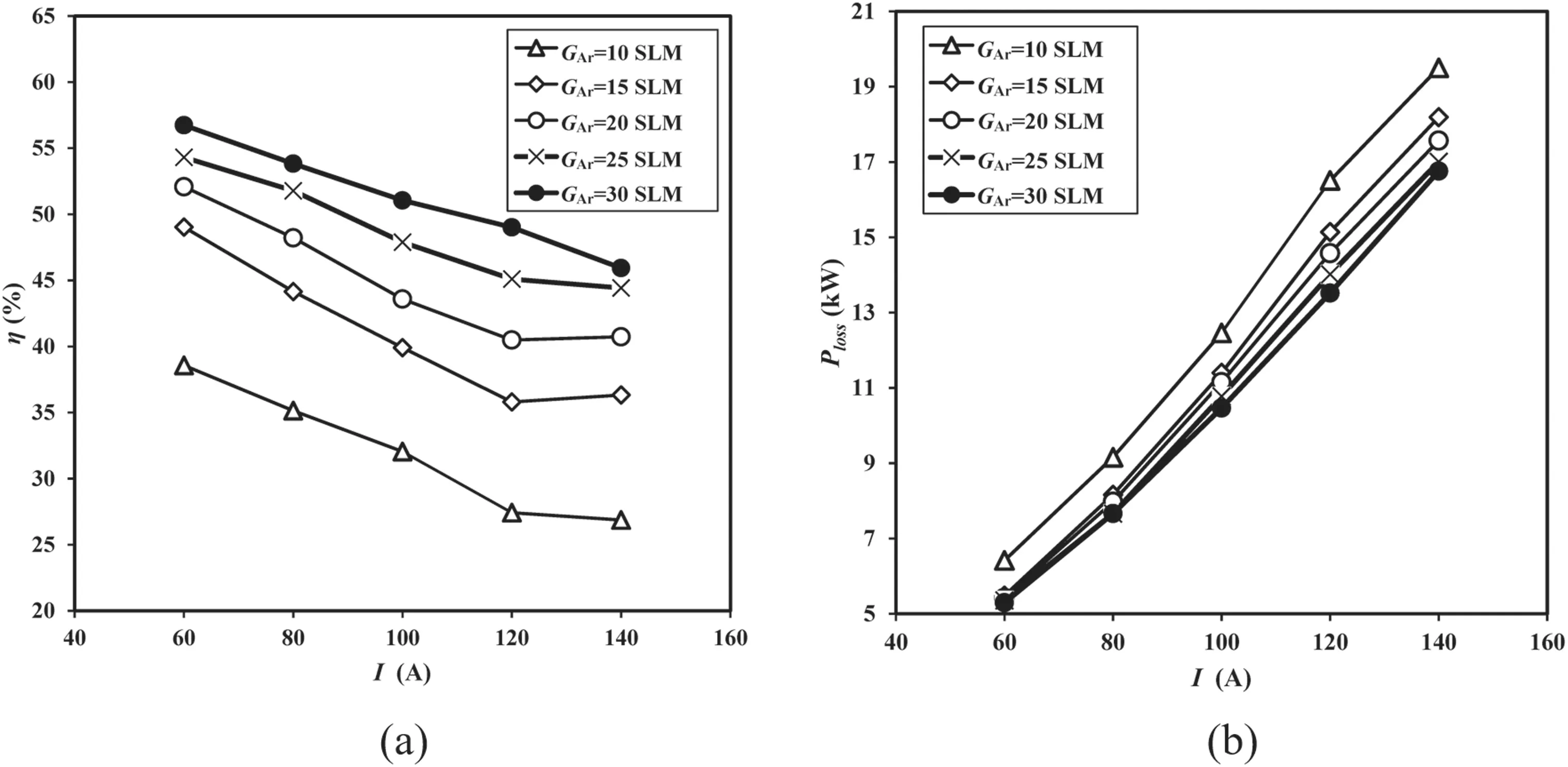
Figure 14.(a)Thermal efficiency of the TCCPT,(b)power of thermal loss of the TCCPT.
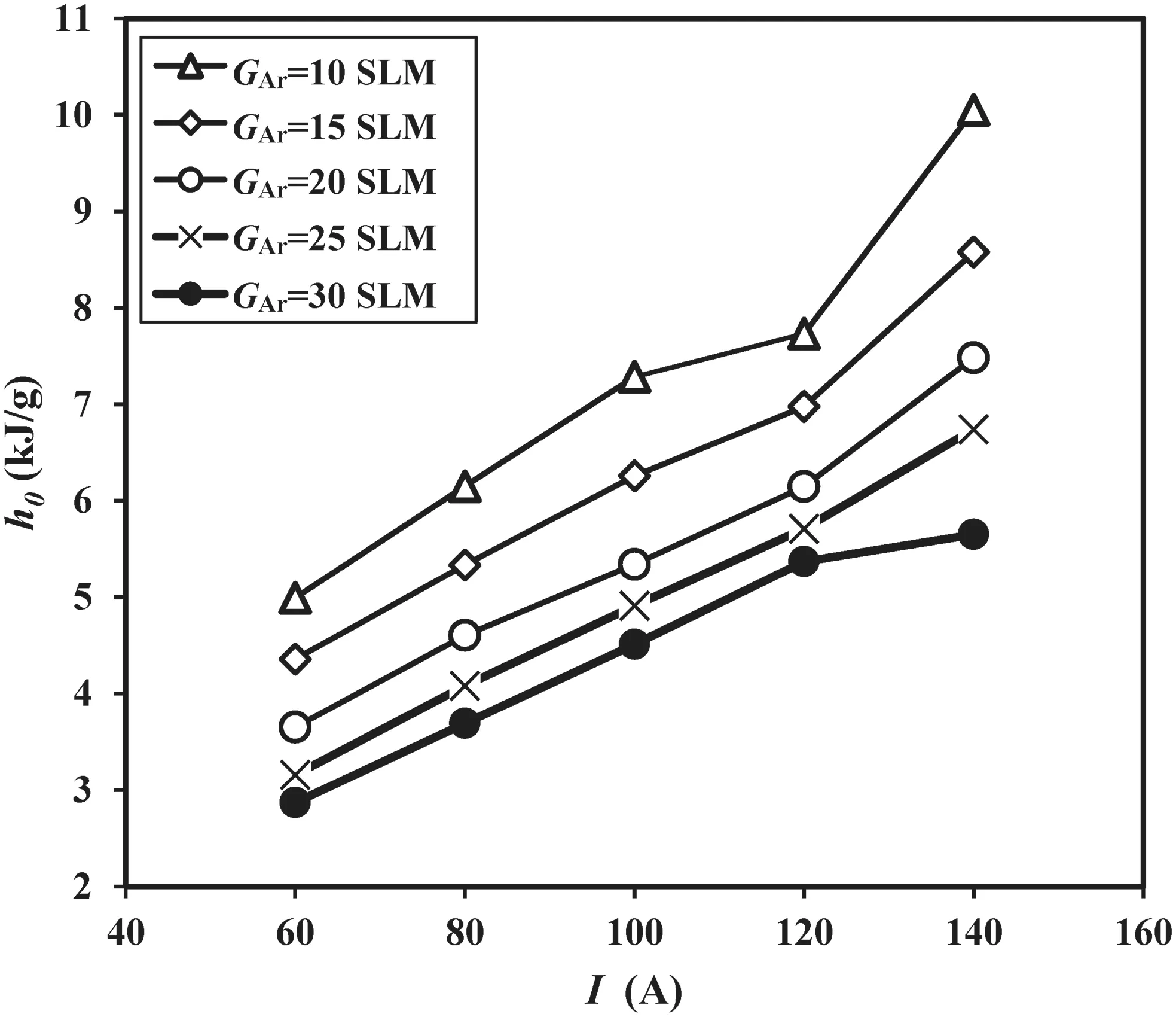
Figure 15.Specific enthalpy of the main plasma jet generated by the TCCPT.
5.Conclusions
This paper presents a new TCCPT for plasma spheroidization of materials.The design and characteristics of the TCCPT have been studied.Following conclusions can be drawn from the study:
(1)The cascade design concept adopted in the proposed TCCPT ensures that the arc voltage is stable,with the fluctuation of the arc voltage within 5.3%.
(2)The TCCPT features a high arc voltage and low arc current.Experiments showed that the arc voltage of the TCCPT can reach 75 V when using argon as the plasma-forming gas.Thus,the service life of the TCCPT,compared with that of a conventional plasma torch,can be enhanced for the same output power.
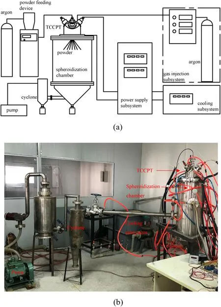
Figure 16.Apparatus for plasma spheroidization:(a)schematic diagram,(b)photo.
(3)The TCCPT can work at a relatively small gas flow rate to meet the needs of plasma spheroidization.
(4)The EI is an effective index to judge the equilibrium state of the plasma torches.Experiments showed that the TCCPT is easy to be maintained at the equilibrium state with the EI of the three plasma jets within 3.5 V.
(5)Plasma spheroidization experiments with the proposed TCCPT demonstrated that the TCCPT is applicable and effective for the spheroidization of powders with wide PSD.In addition,the plasma spheroidization has little effect on the PSD of the powders.
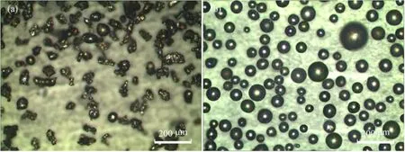
Figure 17.Images of the powders:(a)raw powders,(b)spheroidized powders(I=140 A,GAr=10 SLM,powder flow rate=25 g min−1).
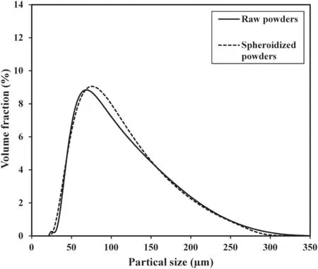
Figure 18.PSD before and after plasma spheroidization.
Acknowledgments
The authors appreciate the supports of the Key R&D Program of Advanced Technology of Sichuan Science and Technology Department(No.2020YFG0111).
猜你喜欢
Plasma Science and Technology(2021年9期)2021-09-10
恋爱婚姻家庭(2021年6期)2021-08-23
做人与处世(2021年9期)2021-08-14
恋爱婚姻家庭(2021年16期)2021-06-07
分忧(2021年5期)2021-05-24
妇女生活(2021年3期)2021-03-28
足球周刊(2017年6期)2017-09-13
新青年(2016年6期)2016-06-15
新青年(2016年6期)2016-06-15
Nuclear Science and Techniques(2014年5期)2014-08-05
 Plasma Science and Technology2020年11期
- Plasma Science and Technology的其它文章
- The effect of resonant magnetic perturbation with different poloidal mode numbers on peeling-ballooning modes
- Soft landing of runaway currents by ohmic field in J-TEXT tokamak
- Numerical simulations of the wavefront distortion of inter-spacecraft laser beams caused by solar wind and magnetospheric plasmas
- Effect of insulating oil covering electrodes on the characteristics of a dielectric barrier discharge
- Numerical study on the modulation of THz wave propagation by collisional microplasma photonic crystal
- Study of partial discharge characteristics in HFO-1234ze(E)/N2 mixtures