
Reconstruction of energy spectrum of runaway electrons in nanosecond-pulse discharges in atmospheric air
2021-06-21 02:00JintaoQIU邱锦涛ChengZHANG章程ZehuiLIU刘泽慧BangdouHUANG黄邦斗andTaoSHAO邵涛
Plasma Science and Technology 2021年6期
关键词:章程
Jintao QIU(邱锦涛),Cheng ZHANG(章程),∗,Zehui LIU(刘泽慧),Bangdou HUANG(黄邦斗) and Tao SHAO(邵涛),∗
1 Beijing International S&T Cooperation Base for Plasma Science and Energy Conversion,Institute of Electrical Engineering,Chinese Academy of Sciences,Beijing 100190,People’s Republic of China
2 University of Chinese Academy of Sciences,Beijing 100049,People’s Republic of China
Abstract This paper presents an experimental investigation into the runaway electron spectrum with a gas diode composed of a rough spherical cathode and plane anode under the excitation of a nanosecond-pulse generator in atmospheric air.The runaway electron beams are measured by a collector covered with aluminum foil with a thickness from 0 μm(mesh grid)to 50 μm.The energy spectrum is calculated by an improved Tikhonov regularization called the maximum entropy method.The experimental results show that the transition state of the discharge consisted of multiple streamer channels stretched from the cathode with glow-like plasma uniformly distributed over the anode.The number of runaway electrons measured by the collector is in the order of 1010 in atmospheric pressure air with a gap spacing of 5 mm and applied voltages of 70–130 kV.The cathode with a rough surface creates a more inhomogeneous electric field and larger emission site for the runaway electrons around the cathode,providing conditions for the coexistence of filamentary streamer and diffuse discharge.The reconstructed spectra show that the energy distribution of the runaway electrons presents a single-peak profile with energies from eUm/2–2eUm/3(Um is maximal voltage across the gap).
Keywords:runaway electrons,diffuse discharge,nanosecond-pulse discharge,spectrum reconstruction
1.Introduction
In 1925,C T R Wilson,who won the Nobel Prize for Physics,first proposed the original concept of ‘fast electrons’(i.e.runaway electrons)[1].According to the electron motion in the cloud chamber,the chance of electrons surviving collision with other particles will be raised by increasing their energy.An electron with a certain velocity can acquire kinetic energy by the acceleration of the electric field until it is deaccelerated by other factors,such as an encounter with the nuclei.Nowadays,many works have proved that discharge can emit high-energy radiation.This is because the electric field in thunderstorms is high enough that electrons can acquire high energy and emit radiation including x-rays[2,3].For example,nuclear reactions were detected in the process of the lightning discharge-based observations of neutron and positron signals,which is indirect evidence of the existence of high-energy electrons[4].
With the development of technology and design,highvoltage generators of several hundred kilovolts have been employed to produce runaway electrons.As a particle accelerator,it produces intense high-energy electron flow,and then produces x-ray radiation through bremsstrahlung[5].However,in order to ensure that the voltage amplitude and rise time reach the range of several hundred kilovolts per nanosecond,the power supply generally works at a frequency of single mode or several Hertz.Despite these shortcomings,we can still get a glimpse of the essence of sub-nanosecondpulse discharges with the help of various diagnostic tools.
For the short gap applied with a voltage rise time of about sub-nanosecond timescale and amplitude of about a few hundred kilovolts,the properties of runaway electrons can be studied,including the energy spectrum and the effect of the runaway electrons on the discharge mode.Babich et al found that after passing 6.5 μm thick aluminum foil,the number of runaway electrons measured in a single pulse was about 107–108in atmospheric pressure air,while it reached 1011in helium at 22 Torr[6].Tarasenko et al measured the spectrum of runaway electrons generated in atmospheric pressure air using a time-of-flight spectrometer and attenuation curves under the excitation of sub-nanosecond-pulsed voltage[7].It was shown that three groups of electrons with different energies existed in the runaway electron spectrum.The maximum of the electron energy distribution for the main group of electrons was less than the energy eUm,where Umwas the maximal voltage across the gap.Only a small number of electrons with anomalous energy higher than eUmwere registered.In addition,the energy distribution of runaway electron beams(REBs)was calculated by introducing a specific stabilizing function in the process of solving the inverse problem.The calculation results showed that the runaway electron energy is widely distributed in the range from dozens of kilo-electron-volts(keV)to several hundreds of keV[8].As for the role of the runaway electrons in the discharge,a Monte-Carlo simulation had been conducted to compare the discharge evolution with the initial electron energy of 20 eV and 20 keV,respectively.The results showed that the REB with initial energy of 20 keV had a positive effect on the discharge evolution in diffuse discharges[9].In addition,the mechanisms of the photoionization and runaway electrons on producing the precursor electrons were simulated by the same model[10].The results showed that the ionization effects on the discharge for these two mechanisms were similar but depended on the applied voltage waveform.
From the aforementioned research,the energy spectra of runaway electrons are closely related to the formation of the pulsed discharges and ignition of diffuse discharge in nanosecond-pulse discharges.Therefore,it is necessary to investigate in detail the energy distribution of electrons with high energy ranging from several keV to hundreds of keV generated by a nanosecond-pulse generator.In this paper,the morphology of the discharge dependence on the increasing of the voltage amplitude is investigated.The REB is measured via a homemade electron collector with a time resolution of 100 ps.The energy distribution is reconstructed by the maximum entropy regularization with a stabilizing function of xln(x)(where x is the reconstructed runaway electron energy distribution matrix).
2.Experimental setup and results
2.1.Experimental setup
The experiments are carried out in a gas-filled diode in open air with a temperature of 20 °C and pressure of 98 kPa.The schematic picture of the experimental setup is shown in figure 1(a).The nanosecond-pulse generator VPG-30-200 is used to produce nanosecond-pulse breakdown in the gas-filled diode,which is similar to the previous work[11].The output voltage pulses have a rise time of ~1.6 ns and a full width at half maximum of 3–5 ns.The amplitudes of the voltage pulses range from 30–200 kV with negative polarity.The discharge is created in the configuration of a rough sphere to plane electrodes.The cathode is a steel sphere with a diameter of 10 mm.The cathode was oxidized for 15 d under atmospheric pressure air with a temperature of 24 °C and relative humidity of about 40% so that the surface of the cathode displays some protrusions visible to the naked eye.With surface-roughness comparison specimens,the roughness Raof the sphere’s surface is about 200 μm(where Rais the arithmetic average of the absolute values of the profile height deviations from the mean line).The anode is an aluminum foil with thickness ranging from 0 μm(mesh grid)to 50 μm.The steel sphere is connected with the output of the nanosecond-pulse generator via a copper rod with a diameter of 3 mm.
The voltage across the gap is measured by a voltage divider mounted on the generator.The divider has a ratio of 1290:1.The discharge current flows through the aluminum foil or mesh grid into the source shell and then into the earth.The runaway electrons are able to penetrate through aluminum foil.Then,the runaway electrons are measured by a Faraday cup-type homemade collector[12].The receiving part has a diameter of 10 mm and a length of 30 mm.It is used to absorb the REB passing through the aluminum foil.The number of runaway electrons can be calculated by integrating the REB.A hollow circular truncated cone with a collector area of 4π cm2forms the electron-collecting part,which reduces the oscillation of the signal compared with a solid collecting part.Electrical signals of the voltage and REB were recorded by an oscilloscope(Lecroy,WaveMaster 808Zi-B).The maximum bandwidth and sampling rate of the oscilloscope were 8 GHz and 40 GS/s,respectively.The luminance images were recorded by a Nikon camera(D7500)mounted with a lens(Tamron,F017).
Typical waveform of the voltage and REB is shown in figure 1(b).The REB occurs in the rise edge of the voltage pulse and its rise time is about 100 ps.It should be pointed out that the diode was discharged ten times before the REB collection to minimize the instability and non-uniformity of emission caused by the uncertainty defect in the cathode surface.In general,when nanosecond pulses are applied to the gas-filled diode,diffuse discharges are generated near the head of the spherical cathode,and then propagate towards the anode.
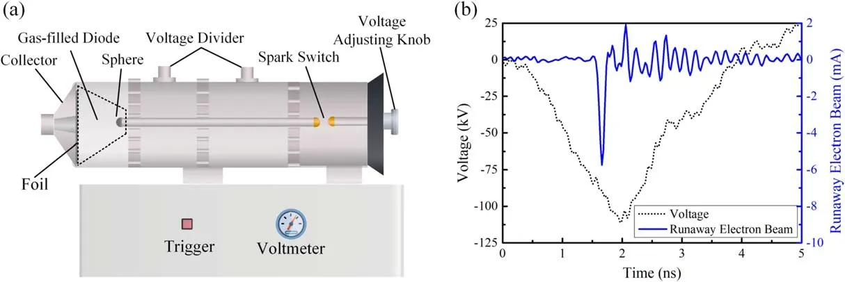
Figure 1.(a)Schematic diagram of the experimental setup and(b)typical waveform of the voltage across the gap and REB.
2.2.Breakdown voltage at different gap spacings
The nanosecond-pulse generator can produce incident waves with different voltage amplitudes via adjusting the primary breakdown gap in the spark switch.The voltage wave will be refracted and reflected when the incident wave reaches the output port.The output voltage can be calculated by the formula:

Therefore,R can be considered infinity and k can be considered as 1 when the breakdown does not happen because the insulation resistance of air is much greater than the wave impedance of the incident transmission line.The incident wave will be totally reflected and the transmission voltage waveand the output voltage will be.When the breakdown occurs,R rapidly decreases,but is still greater than the wave impedance of the incident voltage wave.Althoughis smaller thanit has the same polarity asHowever,due to mismatch of the impedance,the multiple refraction of voltage waves occurs between gaps in the gas-filled diode and spark switch.As a result,the breakdown voltage can be determined according to the point at which the voltage waveform oscillates.Table 1 shows the average breakdown voltage value of 20 discharges when the gap spacings are 3,5,8,10 and 12 mm,respectively.

Table 1.The average breakdown voltage with different gap spacings in the gas-filled diode.
2.3.Morphology of different discharge modes
Figure 2 shows the typical picture of different discharge modes from diffuse discharge to spark discharge while the voltage increases from 60 to 110 kV with the anode changing from aluminum foil to copper plate with a thickness of 1 mm.Because of the uncertainty of the resistance of discharge channel R,the voltage amplitude moves up or down by 10 kV approximately.
Figures 2(a)and(b)show the diffuse discharge in which the air gap spacing is 5 mm and the applied voltage is about 60 and 80 kV,respectively.The discharge at the high-voltage electrode is no longer limited to the bright spots near the cathode.It is shown that multiple cathode flares are produced on the cathode surface and extend 1–2 mm towards the anode.Meanwhile,a uniform and faint discharge area is formed in the anode.
Figure 2(c)shows the transition state from a diffuse discharge to a spark discharge when the applied voltage is about 95 kV.A few bright discharge channels are generated from the surface of the cathode extending forwards to the anode.Meanwhile,a small jet is dragged out of the anode plate propagating into the diode.Discharge channels generated from the anode and cathode are not encountered.The spark channel is not lit and the uniform diffuse discharge area still fills around the diode.
When the applied voltage increases,it enables the electric field to bring jets from the cathode and anode.As they encounter in the middle of the air gap,the spark channel is formed.Figure 2(d)shows the image of the spark discharge when the applied voltage is approximately 110 kV.It can be seen that a bright plasma channel bridges the cathode and anode.The channel consists of several thin filaments.It is very interesting that sometimes many red tracks emit from the surface of the cathode sphere.The small iron particles on the surface of the sphere expand so rapidly that they detach from the cathode surface because of the heat effect caused by the field emission(FE)and explosive emission(EE)of the initial electrons[13,14].

Figure 2.Discharge images with different voltage amplitudes:(a)60 kV,(b)80 kV,(c)95 kV,(d)110 kV;the gap is 5 mm.
2.4.Reconstruction of the energy spectrum of runaway electrons
Figure 3 shows the dependence of the number of runaway electrons on the thickness of the aluminum film ranging from 0 μm(mesh grid)to 50 μm.The total number of runaway electrons with a rough surface is about five times higher than that of a needle/tube-to-plate geometry under the same conditions compared with a previous work[15].Because of the electric field distortion around the iron surface protrusions,every protrusion of the iron surface is capable of being a site for the EE,let alone micro-defects of the surface.Generally,the electric field distortion and growth in quantity of surface defects are the main reasons for the increase in the number of runaway electrons.
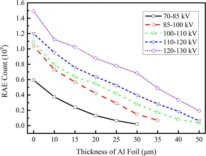
Figure 3.Number of runaway electrons measured by the collector covered by aluminum foil with a thickness range from 0 μm(mesh grid)to 50 μm.
The calculation of the energy distribution of the runaway electrons in the discharge process is a typical ill-posed problem solving the Fredholm integral equation of the first kind with a square integrable kernel function[16].Usually,this equation has a typical form as below:

where F(ε)is the real runaway electron energy distribution function,Aε(,t)is the penetration coefficient function for the electrons with energy ε passing through aluminum foil with thickness t,G(t)is the experimental data of the number of runaway electrons decreasing with the increase in the aluminum foil thickness from t1to t2,and the ε1and ε2are the upper and lower limits of the integral equation.Because of the large condition number of the matrixAε(,t),a small perturbation of G(t),which is inevitable in the process of measurement,can usually lead to an arbitrarily great deviation of F(ε).
The regularization method is adopted to calculate this kind of inverse problem,which is the reconstruction of F(ε)using a known kernel functionAε(,t)and G(t)through discretization.The main idea of regularization is to introduce a suitable stabilizing function Ω(x)and regularization parameter λ,and then an appropriate λ is chosen to balance the stabilizing function Ω(x)and residual erroris the Euclidean norm)through minimizing function M(x):

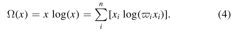
Here,the runaway electron energy distribution is calculated via the maximum entropy regularization method to ensure a positive solution(the number of runaway electrons is positive).In maximum entropy regularization[17],the following discretized nonlinear function is used as the stabilizing function:
The solution algorithm is based on the regularization tools developed by Hansen[18].It should be noted that the calculation here is in normalization form to ensure that it satisfies the ‘Picard condition’ for a reasonable solution[19].First,a test exponential decreasing function F1(ε)is used to test the accuracy of the algorithm.G1(t)is the solution of the direction problem,which is the integral between the given test function F1(ε)and penetration coefficient functionAε(,t)throughout the lower bound with ε1=0 keV and ε2=eUmkeV(corresponding to the cutoff energy for the mesh grid and maximum energy an electron can get through the gap).Then,the solution of the inverse problem F2(ε)is calculated via the maximum entropy regularization through the direct integral solution G1(t).Here,we only give a brief description of the test for the verification of the maximum entropy regularization,as shown in figure 4.The reasonable solution of the test calculation via the maximum entropy regularization shows that the high-energy part fits well but the low-energy part has some deviations.
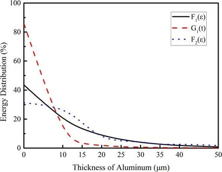
Figure 4.Test results for the regularization.
The regularization parameter is chosen based on the assumption that the percentage of electrons with energy from 67.5–82.3 keV(corresponding to the cutoff energy of aluminum foil with 40 and 50 μm thickness)is decreasing rather than increasing.With the decreasing of regularization parameter λ,the percentage of runaway electrons with higher energy than 67.5 keV is transiting from a monotone incremental function to a monotone decreasing one.Then,as regulation parameter λ is decreasing continuously,the percentage of electrons with energy lower than 32.3 keV(corresponding to the cutoff energy of 10 μm aluminum foil)is decreasing.The above clarifies the balancing effect of the regularization parameter between the residual errorand stabilizing function Ω(x),which assists in the selection of the regularization parameter[17].
Figure 5 presents the energy distribution of runaway electrons after being reconstructed with the maximum entropy regularization method.The energy distribution of the runaway electrons forms a single-peak pattern in the range of about eUm/2 with applied voltage ranging from 70–150 kV.Despite the discharge morphology changes from the corona to diffuse and eventually spark,and along with the increasing of the applied voltage,the peak of the runaway electron energy spectrum gradually shifts towards the direction of high energy.

Figure 5.Reconstructed energy spectra of runaway electrons at different voltages.
3.Discussion
Due to the potential barrier of the metal surface,electrons in metal are usually not capable of crossing this barrier and becoming free electrons.However,in some cases,such as thermal emission[13,20],free electrons in metals can obtain enough kinetic energy,cross the potential barrier,depart from the metal surface and become free electrons.In another case,when a high voltage is applied to the gas diode,the electric field on the electrode surface is so high that the electrons are stripped from parent metal atoms to become free electrons[21].After being dragged out of the metal surface,electrons gain energy under the acceleration of the electric field and lose energy because of ionization and radiation[22].Without regard to the elastic collision,the energy balance of electrons can be described by the following formula[23]:

where ε is the kinetic energy of electrons,x is the location of electrons,E is the local electric field andis the friction force caused by inelastic collision with neutral atoms including energy loss through ionization and radiation.Electrons usually lose most of their energy by ionizing neutral atoms with inelastic collisions.However,as the energy of electrons increases from several eV to tens of keV and even higher,the mean friction force of electrons first increases and then decreases.When the electric field is less than the criteria value with0,the high-energy electrons will gradually lose energy through inelastic collision and radiation and slowly move towards the anode.When the electric field strength reaches the criteria value withthe friction force of electrons moving in gases will be less than the electric field force.Electrons gain energy from electric field continuously and enter the ‘fast’ or ‘runaway’ state[24].
Generally,when the electric field is low at atmospheric pressure,electrons gain energy by the electric field force and lose energy colliding with gas molecules through ionization and radiation.When the electric field reaches the threshold of static breakdown field strength,the inelastic collision between electrons and gas molecules forms electron avalanches.For non-uniform discharge geometry similar to needle-plate structure,a weak corona discharge is formed near the needle electrode.With the increase in electric field,the volume of corona discharge increases gradually until the corona discharge changes into a strong spark discharge[25].For nanosecond-pulse discharges with short gap spacing,there are many initial stages such as FE and EE before a spark channel is lit up in the gap eventually.When the applied voltage is a fast pulse voltage,it is difficult for streamer channels to form because of the rapid development of discharge and the weak heating effect.So there exists a special discharge mode called diffuse discharge or pulse corona discharge between the corona and spark discharge[26].When the applied voltage rises rapidly,the breakdown voltage is 3–8 times higher than the static breakdown field strength and the discharge is guided by runaway electrons.However,runaway electron guided discharges usually consist of cathode flares near the highvoltage electrodes and a few diffuse discharge channels in the gap.
In this investigation,a spherical cathode with a rough surface was used to increase the number of electrons emitted by FE and EE,which further increases the number of discharge channels in the gap.However,the discharge with a rough surface is not only the flare at the high-voltage electrode and the multi-channel discharge in the discharge gap,but the coexistence of the multi-filament discharge and diffuse discharge in the gap,as shown in figure 2.
Due to the strong electric field distortion around small protrusions,electrons cross the potential barrier of the metal surface and inject electrons into the gap at the initial stage[27].Meanwhile,because of the heat process of FE,EE is formed and more free electrons are injected into the gas diode from the protrusions on the cathode surface[28].These free electrons are accelerated under the strongly distorted electric field.A small number of free electrons are accelerated into fast mode in a very short time,and most of them collide with and ionize gas molecules,forming initial streamers,as shown in the middle of figure 6.On the periphery of the cathode,the temperature and degree of gas ionization are highly improved.Streamers are formed and bright discharge channels light up,as shown in figure 2(c).However,as the streamers or bright channels move forward,a small fraction of runaway electrons ionize the neutral particles at the front of the discharge channels,forming pre-ionization.In addition,runaway electrons lose their energy in the process of colliding with gas molecules and the anode plate,bremsstrahlung x-rays occur and emit into the gap[29].This radiation caused by x-rays,combined with runaway electron ionization,forms preionization in the gap and increases the initial ionization in the gap[10].Because of the very short time and limited voltage amplitude of the voltage pulse applied in the diode,streamers formed by pre-ionization are not capable of forming one bright channel penetrating the gap.A relatively uniform discharge occurs in the vicinity away from the cathode.Generally,because of the complex physical process including the emission of electrons and heat effect of FE and EE,preionization from runaway electrons and the short applied time of the voltage pulse,filamentary discharge channels are formed around the cathode and a relatively uniform discharge area arises around the anode.
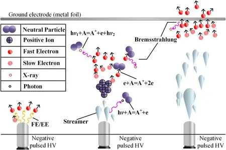
Figure 6.Schematic diagram of the runaway electron guided discharge.
For a fixed discharge structure,the generation of runaway electrons is mainly affected by the applied voltage,gas species and pressure P,i.e.the reduced field strength E/N[30].When external voltage is applied,the electric field is relatively low.The E/N is only enough to form the ionization of the gas in a very small vicinity around the protrusions but not enough to generate runaway electrons with energy penetrating the diode.Then,the voltage continues to rise and the electric field around the protrusions will be large enough to form EE with a relatively low voltage[31].The runaway electron generation process occurs.Because of the short rise time(~1.6 ns)of the applied voltage,the gas-ionization process and runaway electron generation process very likely happen within several hundred picoseconds[32].As the applied voltage consciously increases,runaway electrons cross the gap under the acceleration of the electric field and leave preionization behind in their path,lighting a more uniform discharge in the gap[9].But when the applied voltage amplitude is large enough to multiply the ionization process exponentially,a spark will form in the gap instead of a diffuse discharge.
For the runaway electron energy spectrum reconstruction,because of the very uncertainty,complexity and nonlinear nature of the ill-posed inverse problem[33],it is a significant challenge to achieve accurate energy distribution of the electrons through experiments.Some researches use Monte-Carlo simulation to obtain the collision of electrons with heavy metal atoms[34]and further obtain the original spectrum of the electrons with high energy.Despite the thremendous amount of work that has gone into programming and calculation,there exists an obstacle that almost all the calculation methods hardly simulate the energy absorption for electrons passing through attenuated metal foil with energy amounts of tens to hundreds of keV.After the discrete‘Picard condition’is satisfied and testification with a known function,with proper choice of the regularization method and regularization parameter,the reconstruction of the spectrum may lead to a reasonable solution giving perspective to the runaway electron energy distribution.Consistent with previous works[8],the main distinguishing feature of the reconstructed spectrum of runaway electrons is a single-peak pattern from eUm/2–2eUm/3.The peak energy of runaway electrons shifted to higher energy with an increase in voltage,which indicates the validity of the reconstruction.
It should be pointed out that the reconstruction method only gives us a general estimated spectrum of the runaway electrons.There are still some limitations in the investigation:(1)the uncertainty from runaway electron generation.Because of the heat effect of the FE and EE,the microstructure of the cathode surface will be different between discharges,which has an influence on the runaway electron generation.In addition,the voltage amplitude and divergence between discharges will also introduce uncertainty;(2)errors from the measurement.The collector part is a cone with an electron-collecting area of 4π cm2,which clearly cannot collect all of the electrons able to penetrate the aluminum foil,and the collector part is not placed in a vacuum,which makes the measurement values smaller than the actual ones;(3)errors induced by the calculation.The reconstruction introduces a stabilizing function and a balance parameter to disrupt the ill-posed nature of the inverse problem,which draws additional errors in the calculation.
4.Conclusion
This paper investigates the discharge morphology excited by a nanosecond-pulse generator.The energy spectrum of runaway electrons is reconstructed via an expanding Tikhonov regularization method using maximum entropy xln(x)as the stabilizing function.The effect of the voltage amplitude on the discharge modes and runaway electron energy distribution is studied.The experimental results show that the discharge changes from a diffuse state with multiple discharge channels around the cathode to a spark state with the voltage amplitude increasing from 80 to 120 kV.Because of every protrusion on the cathode surface being the emission site of the runaway electrons,the total number of runaway electrons passing through a mesh grid is in the order of 1010.Furthermore,with the logical choice of balance parameter λ between the stabilizing function and remainder error term,the reconstructed spectrum of runaway electrons by the maximum entropy regularization method shows a single-peak profile from eUm/2–2eUm/3.The energy distribution of electrons ranging from several keV to hundreds of keV generated by a nanosecond-pulse generator is crucial to the understanding of the inhomogeneous nature of the diffuse discharge.
Acknowledgments
This work was supported by the National Science Fund for Distinguished Young Scholars(Grant No.51925703),National Natural Science Foundation of China(Grant Nos.52022096 and 51907190)and the Royal Society–Newton Advanced Fellowship,UK(Grant No.NAFR2192117).
猜你喜欢
水土保持通报(2022年3期)2022-10-16
山西青年(2021年14期)2021-11-27
知识文库(2017年21期)2017-10-20
今古传奇·故事版(2017年17期)2017-10-17
故事会(2015年20期)2015-05-14
北京教育·高教版(2015年3期)2015-04-03
中国校外教育(下旬)(2014年1期)2014-03-22
小小说月刊(2013年11期)2013-05-14
 Plasma Science and Technology2021年6期
- Plasma Science and Technology的其它文章
- Diagnostics of a microhollow cathode discharge at atmospheric pressure
- The investigation of OH radicals produced in a DC glow discharge by laser-induced fluorescence spectrometry
- Multiple current peaks and spatial characteristics of atmospheric helium dielectric barrier discharges with repetitive unipolar narrow pulse excitation
- Study of the influence of discharge loop parameters on anode side on generation characteristics of metal plasma jet in a pulsed vacuum discharge
- Nonlinearity of initiating and extinguishing boundaries of DBDs with airflows
- Study of double-chamber air arc plasma torch and the application in solid-waste disposal