
Effect of single-legged coil on 3D plasma boundary corrugation in EAST
2021-10-31 08:15QibinLUAN栾其斌WendaZHANG张闻达YoujieDENG邓有杰YanfeiWANG王燕飞LiLI李莉YueqiangLIU刘钺强XiaojiangHUANG黄晓江andFangchuanZHONG钟方川
Plasma Science and Technology 2021年10期
关键词:李莉
Qibin LUAN (栾其斌), Wenda ZHANG (张闻达), Youjie DENG (邓有杰),Yanfei WANG (王燕飞), Li LI (李莉), Yueqiang LIU (刘钺强),Xiaojiang HUANG (黄晓江) and Fangchuan ZHONG (钟方川)
1 Faculty of Electronic information and Electrical Engineering, Dalian University of Technology, Dalian 116024, People’s Republic of China
2 School of Physics, Dalian University of Technology, Dalian 116024, People’s Republic of China
3 College of Science, Donghua University, Shanghai 201620, People’s Republic of China
4 General Atomics, San Diego, CA 92186-5608, United States of America
Abstract A single-legged coil behind the lower divertor and covering a 120°toroidal angle is utilized in a recent EAST discharge, for the purpose of increasing the wetted area of the divertor surface by locally modifying the magnetic field near the X-point.The plasma response, in particular, the plasma boundary surface corrugation due to the single-legged coil current, is modeled by the updated MARS-F code, by computing the plasma displacement for all important toroidal harmonics (n=1, 2, 4 and 5) associated with the partial toroidal coverage by the coil.The plasma response produced by the single-legged coil is found to be non-local and is of the kinkpeeling type.For a reference EAST plasma with a lower single-null magnetic configuration,the plasma boundary corrugation near the X-point, produced by the upper single-legged coil, is about twice as large as that produced by the lower single-legged coil,despite the proximity of the latter to the X-point.
Keywords: single-legged coil, plasma response, EAST
1.Introduction
High heat flux on the plasma-facing components, due to various plasma perturbations, is a challenging issue for modern tokamaks, especially for future fusion reactors [1].Increasing the wetted area of the divertor is a plausible way to enhance the ability of the divertor to endure high heat flux from the plasma region.
A new type of divertor has recently been developed in EAST, which is referred to as the Fishtail divertor [2].This divertor concept consists of a Fishtail-coil and the conventional divertor in EAST, where the Fishtail-coil is a singlelegged coil installed behind the lower divertor.In recent EAST discharge, this Fishtail-coil (single-legged coil) only covers a 120° toroidal angle.The other part of the (closed)coil current circuit is located outside the device far away from the plasma.Since the Fishtail-coil is close to the divertor, it can produce a magnetic field, with moderate coil current comparable to the equilibrium magnetic field near the divertor region.In other words,the magnetic footprint on the divertor surface can be modified by the Fishtail-coil.In particular,it is expected that the wetted area on the divertor surface, due to heat flux, can be widened.This is the main purpose of installing the Fishtail-coil in EAST experiments.
However, besides changes to the vacuum magnetic field near the divertor, the plasma boundary can also be modified by the single-legged coil current, manifested as the boundary surface corrugation due to the plasma displacement in the edge region.The latter is due to the plasma response to the magnetic field perturbation produced by the coil current.As shown in many previous experimental and theoretical studies[3–6], the plasma response plays an important role in controlling the edge-localized modes (ELMs) by resonant magnetic perturbations(RMPs).It is therefore of high interest to investigate how the EAST plasma will respond to the magnetic field produced by the single-legged coil current,assuming the maximal current level as designed for experiments.
Previous work [5, 7–9] has shown that 3D plasma boundary corrugation is an important measure of the plasma response to the externally applied magnetic field perturbation.In this work, we compute the plasma boundary displacement due to the single-legged coil current, utilizing the MARS-F code[10].Due to partial coverage of the toroidal angle by the single-legged coil, field perturbations with multiple toroidal harmonics are generated, and the plasma response to the dominant toroidal harmonics needs to be modeled.Because of the special coil current arrangement for the single-legged coil(compared to the conventional ELM control coils), the coil model within MARS-F has to be updated first,which we will also describe in this work.
The paper is organized as follows.Section 2 describes the plasma and coil models assumed in this study, including the adopted EAST equilibrium.Section 3 reports the modeling results of the plasma boundary corrugation due to the singlelegged coil as designed in EAST.Section 4 reports the modeling results, hypothetically assuming that the singlelegged coil were installed at the upper divertor.Section 5 summarizes the work.
2.Models and formulation
In this section, we introduce the single-legged coil design in EAST and explain the corresponding numerical model implemented in MARS-F.We start by describing the plasma equilibrium adopted in this study.
2.1.Plasma equilibrium
The equilibrium is reconstructed from the EAST discharge 52340 at 3450 ms, representing a reference plasma from the ELM control experiments [11].Note that no Fishtail divertor had been installed when this discharge was carried out.Radial profiles of the plasma safety factor and the equilibrium pressure are shown in figure 1, whereψPis the normalized equilibrium poloidal magnetic flux.The safety factor values at the magnetic axis and at the 95% poloidal flux are 0.933 and 5.059, respectively.
2.2.Single-legged coil configuration
As mentioned before,the single-legged coil in EAST includes a single coil located at (1.87 −1.09 m) on the (R,Z) poloidal plane and just behind the lower divertor[2].The coil location is indicted in figure 2(a),where for reference,we also plot the upper and lower rows of the ELM control coils in EAST.
The ELM control coils in EAST are composed of eight window-frame coils in each row,with each coil covering 37°along the toroidal angle.This single-legged coil is very different—it in fact consists of only a single coil (with single turn) in the poloidal cross-section (figure 2(a)).It extends to 120° along the toroidal angle.The circuit is closed by wires that are installed farther away from the plasma.Therefore,these additional wire segments do not provide a significant contribution to the vacuum field perturbation near the plasma.
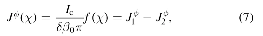
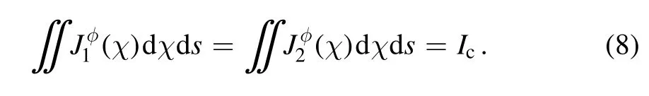
The peculiar geometry of the single-legged coil generates multiple toroidal harmonics for the given coil current, as shown in figure 2(b).Besides then=0 component, which contributes to the equilibrium field, the main sidebands are the toroidal mode harmonics ofn=1, 2, 4 and 5.The toroidal spectrum of the coil current is calculated using the following formula:

whereH(φ) is the Heaviside function equal to 1 for 0≤φ≤2π/ 3,and 0 elsewhere.The main non-axisymmetric sidebands are also documented in table 1.The actual current flowing in the single-legged coil is fixed at the maximal level of 5 kAt(single turn).Note that then=3k(k=1,2, 3, …) components of the coil current vanish due to the designed toroidal coverage(120°)of the single-legged coil,as is also evident from equation (1).Note also that the toroidal Fourier components of the coil current,I,ncoilare generally complex numbers.The phase of the complex number cannot be ignored when computing the total plasma response.

Table 1.Dominant non-axisymmetric toroidal spectrum of thesingle-legged coil current.Shown are the coil current amplitude for each nth toroidal component, current amplitude ratio in percentage and current ratio including the phase.The actual current flowing in the single-legged coil is fixed at 5 kAt.
In this work, we focus on modeling the plasma response and resulting boundary corrugation to the non-axisymmetric vacuum magnetic field components produced by the singlelegged coil.A DC current is assumed in the modeling,although AC current has been applied in experiments.In terms of the plasma response, the main AC effect is the reduction of the actual field reaching the plasma, due to shielding by various conducting structures surrounding the coil.Some of the conducting structures (e.g.the passive stabilizing plate) are of 3D geometry and cannot be properly modeled by MARS-F.However, this is not an issue with the DC single-legged coil current.
We model the linear plasma response to the single-legged coil current, where the linear superposition principle applies.This means that we will compute the plasma response to each of the toroidal Fourier harmonics of the coil current with MARS-F, then sum all the response fields together to obtain the total field.
2.3.MARS-F formulation and single-legged coil model
In this work,we utilize the MARS-F code[10]to compute the linear plasma response to the single-legged coil.In the plasma region, MARS-F solves the linearized single fluid, resistive and full magnetohydrodynamic (MHD) equations in general toroidal geometry.For the response problem, the main equations read as follows:
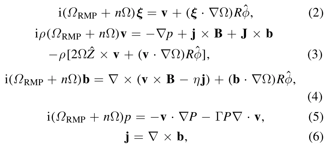
where the variablesξ,v, j,b andpare the plasma displacement, perturbed velocity, current, magnetic field and pressure,respectively.ρ,B,J,Pand Ω denote the equilibrium density, magnetic field, current, pressure and angular frequency of the toroidal rotation, respectively.Ris the plasma major radius,φˆthe unit vector along the toroidal angle andnthe toroidal harmonic number.
The single-legged coil current, as a source term, enters into the MHD equation via Ampere’s law ∇× b =jRMP.The previous MARS-F implementation always assumes that the coil current flows in a closed circuit.In other words,there are always two parallel legs of the coil along the toroidal/poloidal angle, where currents flow in opposite directions.However, the single-legged coil has only one leg along the toroidal angle for the current-carrying segment that we model.Therefore, we need to update the code in order to accommodate the one-leg geometry.
To model the conventional window-frame ELM control coils, MARS-F assumes the following distribution for the toroidal component of the coil current density along the poloidal angleχ,
To model the single-legged coil,we only assume one leg with the coil current density represented by.The MARS-F code is updated to include this single-leg option.Obviously,the new implementation can also be used to recover the conventional window-frame coil, by assuming two sets of coils with opposite signs of current.This consistency check has been carried out using the upper set of ELM control coils shown in figure 2(a) as a test example.First, the perturbed magnetic field produced by the upper row is computed with standard MARS-F implementation.Next,two perturbed fields are computed with the new implementation, assuming the single-leg geometry and opposite coil currents.These two fields are then superposed and compared with that from the first step.The results are identical (figure 3), with or without the inclusion of the plasma response.Note that the amplitude of the coil current is assumed to be 1 kAt in this test,and the toroidal spectrum is chosen to ben=1–3.
For example, figure 3(a) compares radial profiles of the amplitude of the poloidal Fourier harmonicsm=1–8 of then=1 radial field perturbation, between the two MARS-F implementations.Both the vacuum field(solid)and total field perturbation are compared together with the resistive plasma response(dashed).The corresponding curves overlap between the two implementations.The amplitude of the resonant harmonics is extracted from figure 3(a) and plotted in
figure 3(b)forn=1 RMP.The results again overlap between the two implementations.Similar tests have also been performed forn=2 and 3 RMP, with good agreement, as reported in figures 3(c) and (d), respectively.
3.Single-legged coil-induced plasma boundary corrugation
We compute the plasma response to the single-legged coil,with the coil current model described in the previous section.We focus on the plasma boundary corrugation,i.e.the normal displacement of the plasma boundary surface as one of the key indicators of the plasma response.This choice is motivated by the following considerations.
First, according to previous studies [5–7, 12, 13], the normal displacement of the plasma boundary near the X-point(for divertor plasmas),ξxpt,together with the resonant radial magnetic field perturbation near the plasma edge,,serves as important figures of merit for predicting ELM control by RMPs in tokamak experiments.These two figures of merit,which often predict similar optimal ELM control coil configurations, have been successfully applied to a range of ELM control (either mitigation or suppression) experiments including MAST [12], ASDEX Upgrade [6, 7], EAST [14],DIII-D[15,16]and HL-2A[17].The same criteria have also recently been applied to ELM control optimization in DEMO[18] and ITER [8, 9].
Second, partial toroidal coverage of the single-legged coil implies the co-existence of several toroidal harmonics of comparable amplitude (figure 2(b)).The radial locations of resonant radial magnetic perturbations(near the plasma edge)are obviously different for differentn, making it difficult to employ thecriterion.The X-point displacement criterionξxpt,on the other hand, is defined for the plasma boundary surface (which is independent of the toroidal mode number)and can thus be easily superposed for RMP fields with multiple toroidal harmonics.This superposition is important in order to investigate the plasma response to the single-legged coil with partial toroidal coverage.
We start by reporting the MARS-F computed plasma response for each individual-nRMP field produced by the single-legged coil current (at 5 kAt).Figure 4 shows results for then=1 component.For comparison, we consider here both figures of merit mentioned before.Figures 4(a) and (b)plot the radial distribution of the poloidal Fourier harmonics of the resonant radial magnetic field, for both then= 1 vacuum field and the totaln=1 field including the plasma response.Compared to the vacuum field, a strong screening of the resonant field perturbation occurs, in both the plasma core and edge regions.Figure 4(c) plots the normal displacement amplitude of the plasma surface along the geometric poloidal angle.The X-point is located at −103°.We are mostly interested in the local maximum of the plasma surface displacement near the X-point, which is about 1.07 mm in our case.The overall structure of the plasma displacement, including that inside the plasma, is shown in figure 4(d).An interesting observation is that large plasma displacement occurs near both the top and bottom of the plasma(as also confirmed by figure 4(c)),despite the fact that the single-legged coil is located only near the lower divertor.This means that the plasma response is not a local phenomenon.The computed displacement is strongest near the plasma edge, indicating a peeling-like response.
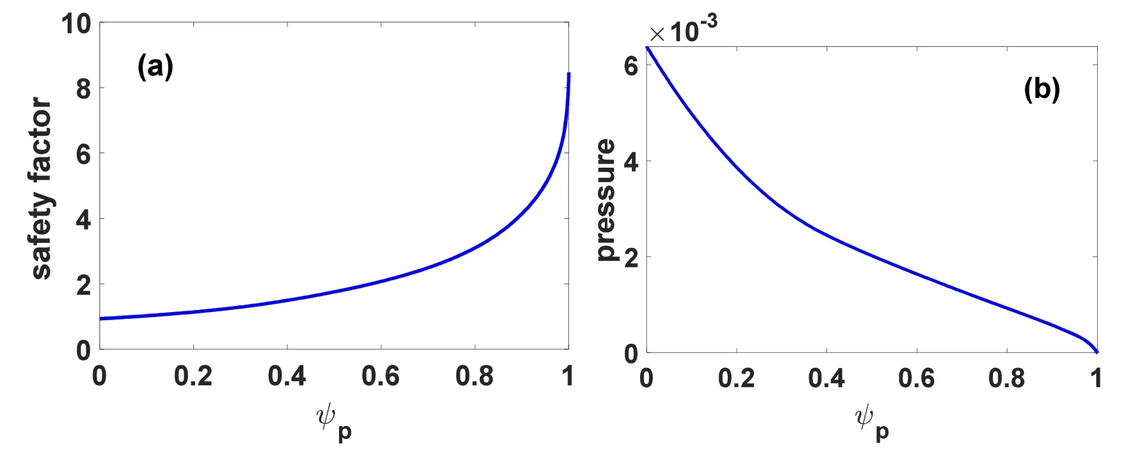
Figure 1.Radial profiles of (a) the safety factor and (b) the equilibrium pressure normalized by /μ 0,for the EAST discharge 52340 at 3450 ms.Here,ψp is the normalized equilibrium poloidal magnetic flux.

Figure 2.(a)Poloidal cross-section of the plasma boundary(black curve),the ELM control coils(blue squares)and the single-legged coil(red circle).(b) Toroidal spectrum of the single-legged coil current, normalized by the actual current flowing in the coil.
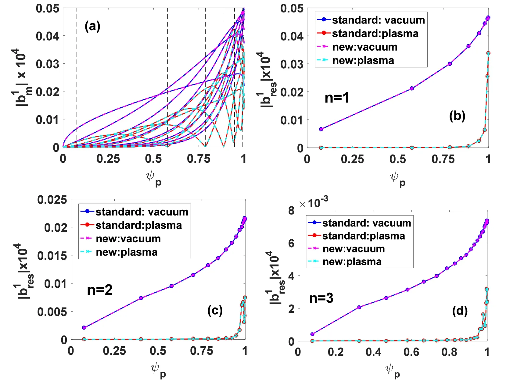
Figure 3.Comparison of the resonant radial magnetic field perturbation between the standard and new implementations of MARS-F for the coil current.Both the vacuum field and total field perturbation are compared together with the plasma response: (a) radial profiles of the m=1–8 poloidal Fourier harmonics of the n=1 radial field perturbation, (b)–(d) amplitude of the pitch resonant radial magnetic field components at the corresponding rational surface locations for the n=1,2,3 perturbation,respectively.The upper row of the ELM control coils in EAST is considered, with a coil current of 1 kAt.Vertical dashed lines in (a) indicate the radial location of the n=1 rational surfaces.

Figure 4.MARS-F computed plasma response to the n=1 single-legged coil current.(a) Radial distribution of the poloidal Fourier harmonics of the resonant radial magnetic field perturbation,with the vacuum field(in blue)being compared to the total field perturbation(in red)including the plasma response,(b)amplitude of the resonant radial magnetic field components at the corresponding rational surfaces,for the vacuum field(in blue)and the total field(in red),respectively,(c)amplitude of the normal displacement of the plasma boundary surface along the geometric poloidal angle, (d) amplitude of the normal displacement at the poloidal cross-section of the plasma.Vertical dashed l ines in(a)indicate the radial location of the n=1 rational surfaces.X-point corresponds to the poloidal angle of −103°in(c).Single-leggedcoil current amplitude for n=1 harmonic? is assumed to be 5 kAt.

Figure 5.MARS-F computed plasma response to the (a)–(b) n=2, (c)–(d) n=4 and (e)–(f) n=5 components of the single-legged coil current.Amplitude of the normal displacement of the plasma boundary surface along the geometric poloidal angle (left panels) and normal displacement at the poloidal cross-section(right panels).X-point corresponds to the poloidal angle of −103°in the left panels.Single-legged coil current amplitude for each harmonic is assumed to be 5 kAt.
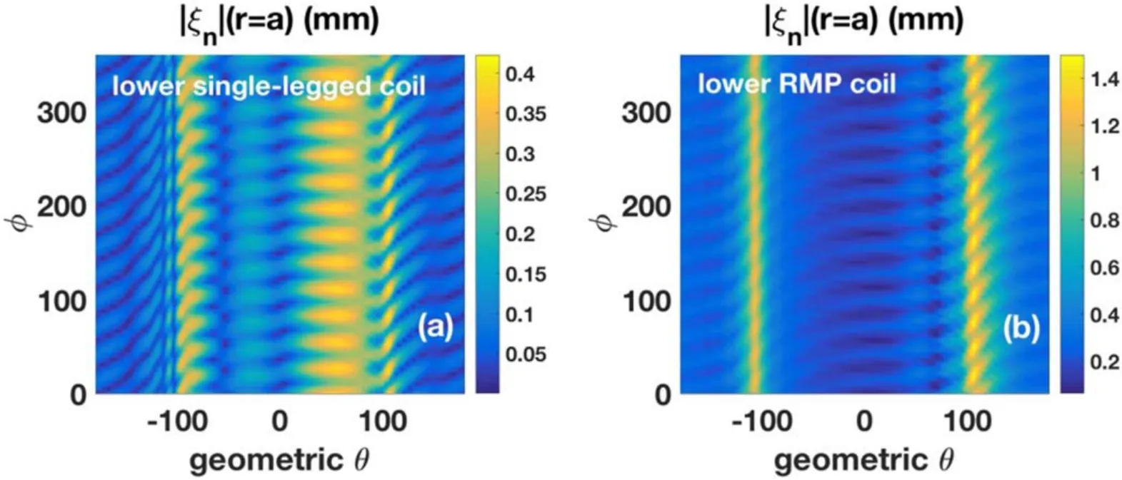
Figure 6.Comparison of the overall plasma boundary corrugation amplitude along both the poloidal and toroidal angles,produced by(a)the single-legged coil and(b)the lower row of ELM control coils.Here,the amplitude of the coil current is fixed at 5 kAt in both(a)and(b),and the same set of weighting factors, Cn from equation (10), are assumed for the toroidal sidebands of the single-legged coil and the ELM control coils.

Figure 7.MARS-F computed plasma response to the(a)–(b)n=1,(c)–(d)n=2,(e)–(f)n=4 and(g)–(h)n=5 components of the upper single-legged coil current.Amplitude of the normal displacement of the plasma boundary surface along the geometric poloidal angle (left panels) and the normal displacement at the poloidal cross-section (right panels) are plotted.X-point corresponds to the poloidal angle of−103° in the left panels.Single-legged coil current amplitude for each harmonic is assumed to be 5 kAt.

Figure 8.Computed plasma boundary corrugation along both the poloidal and toroidal angles, assuming the upper single-legged coil with 5 kAt current.The n=1, 2, 4, 5 toroidal harmonics of the plasma response are superposed.
The normal displacement amplitude forn=2, 4 and 5 single-legged coil currents is summarized in figure 5.The corresponding coil current amplitude is again fixed at 5 kAt,in order to compare it with the results for then=1 coil current.The MARS-F computed local maxima of the plasma surface displacement near the X-point are 0.757, 0.099 and 0.022 mm, with then=2, 3 and 5 single-legged coil currents,respectively.It is evident that,with the same amplitude of the coil current for each toroidal harmonic, the plasma response to then=1 (5) coil configuration produces the largest (smallest) X-point displacement.
Several other interesting observations can also be made from figure 5.First, a relatively large plasma displacement is generally computed near the top and bottom of the torus.This is despite the fact that the external field perturbation is produced by the single-legged coil current located only near the bottom (behind the lower divertor).This again confirms the non-local nature of the plasma response,for all the low-ncoil current components.
Next, although the plasma surface displacement near the X-point,∣ξxpt∣,is weakest for then=5 coil current, the ratio ofξmid∣∣toξxpt∣∣is largest.Here,ξmid∣∣denotes the plasma surface displacement at the outboard mid-plane.This is a clear indication of the kink-like plasma response [12] to then=5 single-legged coil current.
As mentioned before, the plasma response to each individual toroidal component of the single-legged coil current can be superposed, in order to construct the overall response to the ‘physical’ coil current that contains a range of toroidal spectra.In particular,the overall plasma boundary corrugation amplitude,which now varies along both poloidal and toroidal angles, can be obtained utilizing the coil current weighting factors documented in table 1

whereCnis the corresponding (complex) weighting coefficient for eachn-component of the single-legged coil current.
In order to better understand the efficiency of the singlelegged coil geometry (in terms of the generated plasma corrugation magnitude),we compare it with that produced by the lower row of the ELM control coils in EAST, but assuming the same coil current and same sideband distribution as that of the single-legged coil.The plasma displacements from different toroidal harmonics are superposed following equation (10), and compared between the single-legged and RMP coils in figure 6.Two interesting observations can be made here.First, the maximum displacement along the toroidal angle and near the X-point (at −103° poloidal angle),∣ξxpt∣ ,is 0.35 mm due to the single-legged coil current(figure 6(a)).This value is about four times smaller than that(1.27 mm) produced by the lower row of the ELM control coils with the same current configuration.This difference is due to two factors: (i) the lower row of ELM control coils is closer to the plasma than the single-legged coil; (ii)the ELM control coils geometrically cover a finite poloidal angle due to their window-frame structure.
Next, we find it interesting that despite being a singlelegged coil (with a single turn) located behind the lower divertor, the single-legged coil is capable of generating a plasma response that is global, i.e.not just located near the X-point.Large displacement is also triggered near the top of the plasma, which is far from the single-legged coil location.This global response effect is similar to that produced by the ELM control coils.In fact, maximum displacement occurs near the top of the plasma at the poloidal angle of 106°,with both types of coil geometry.The corresponding values are 0.42 mm with the single-legged coil and 1.5 mm with the ELM control coils.
4.Effect of upper single-legged coil on plasma boundary corrugation
Due to engineering constraints, the single-legged coil is applied for an upper single-null magnetic configuration in EAST experiments,in contrast to the lower single-null plasma that we adopt in this study.Therefore, to better simulate the experimental situation, we assume that the single-legged coil is located near the upper top,at(R=1.87 m,Z=1.09 m)in the MARS-F model,while keeping the same lower single-null plasma equilibrium.In what follows,we investigate the effect of this new single-legged coil configuration on the plasma response.
We again start by comparing the plasma response level among various toroidal sidebands of the single-legged coil current, assuming the same current of 5 kAt for eachn-harmonic.The computed normal displacements for then=1,2,4, 5 components, plotted in figure 7, show that the local maxima of the plasma surface corrugation near the X-point are 2.022, 0.831, 0.11 and 0.024 mm, respectively, i.e.sharply decreasing with increasingn-number.
Compared to the results reported in section 3, we find that the lower and upper single-legged coils produce a similar plasma response to each toroidal harmonic.The strongest plasma surface distortion generally occurs near the top and bottom of the torus.The plasma displacement near the(lower single-null) X-point, produced by the upper single-legged coil,is slightly larger than that produced by the lower singlelegged coil.This again indicates the non-local nature of the plasma response.Despite a generally small displacement, the displacement ratio of the outboard mid-plane to the X-point,∣ξmid∣ /∣ξxpt∣,is largest for then=5 toroidal component.
Figure 8 plots the computed plasma boundary corrugation along the poloidal and toroidal angles, produced by the upper single-legged coil, after superposition of then=1, 2,4, 5 contributions according to equation (10).Compared to the lower single-legged coil (figure 6(a)), the upper singlelegged coil produces about double (0.651 mm versus 0.344 mm) the plasma displacement near the X-point,assuming the same (lower single-null) plasma and same coil current of 5 kAt.Note that this is despite the much larger distance between the upper single-legged coil and the X-point.However,the X-point displacement with both singlelegged coils is still lower than that produced by the lower row of ELM control coils (figure 6(b)) with the same coil current configuration.
5.Conclusion and discussion
The Fishtail divertor, composed of a single-legged coil and the lower divertor, is designed in EAST for the purpose of modifying the local magnetic field structure near the X-point.However, our modeling shows that the single-legged coil is capable of triggering a more global plasma response.
The single-legged coil is modeled as a single-current filament in the updated MARS-F code, covering a 120° toroidal angle.This finite toroidal coverage is realized by considering a range of important toroidal sidebandsn=1, 2, 4,5.Modeling result shows that the plasma response amplitude,in terms of the boundary corrugation, drops sharply with increasing toroidal mode number, assuming the same coil current.On the other hand, based on the computed response for each individual toroidal harmonic, the total plasma response to the single-legged coil current can be reconstructed via linear superposition with proper weighting factors, producing plasma surface corrugation that varies along both poloidal and toroidal angles.
The total response shows that the single-legged coil triggers large plasma displacement near the top and bottom of the torus.This holds, independent of whether the single-legged coil is placed near the top or bottom of the plasma,for the same lower single-null equilibrium.Thus, the modeling results show that (i) the plasma response to the single-legged coil current is non-local and (ii) the total response is predominantly of the kink-peeling type.
Another interesting result is that we find that for a discharge with the lower single-null magnetic configuration, the upper single-legged coil produces about double the X-point displacement compared to the lower single-legged coil,despite the fact that the latter is much closer to the X-point.There seems to be a certain correlation between the X-point displacement and the magnetic footprint on the divertor surface[19,20].The last result here suggests that a single-legged coil, placed opposite to the X-point on the poloidal plane (as in the EAST experiment),may be more effective in producing a wider magnetic footprint.Direct modeling of the magnetic footprint due to the single-legged coil,based on the MARS-F computed plasma response field, is the next step in our investigation.
Acknowledgments
This work is funded by the Fundamental Research Funds for the Central Universities (No.2232021G-10), National Natural Science Foundation of China (Nos.12075053, 11505021 and 11975068) and the National Key R&D Program of China(Nos.2017YFE030052, 2017YFE0301100, 2017YFE0301104,2017YFE0300500 and 2017YFE0300501).The work was also supported by the U.S.DoE Office of Science (Nos.DEFG02–95ER54309 and DEFC02–04ER54698).This paper was prepared as an account of work sponsored by an agency of the United States Government.Neither the United States Government nor any agency thereof,nor any of their employees,makes any warranty, express or implied, or assumes any legal liability or responsibility for the accuracy,completeness,or usefulness of any information, apparatus, product, or process disclosed, or represents that its use would not infringe privately owned rights.Reference herein to any specific commercial product,process,or service by trade name, trademark, manufacturer, or otherwise,does not necessarily constitute or imply its endorsement,recommendation or favouring by the United States Government or any agency thereof.The views and opinions of the authors expressed herein do not necessarily represent or reflect those of the United States Government or any agency thereof.The views and opinions expressed herein do not necessarily reflect those of the European Commission.
猜你喜欢
大众文艺(2021年17期)2021-09-29
大众文艺(2021年17期)2021-09-29
发明与创新·中学生(2021年3期)2021-03-28
学生天地·小学中高年级(2019年4期)2019-05-04
伴侣(2018年9期)2018-09-19
北京广播电视报(2018年1期)2018-07-27
教育教学论坛(2017年36期)2017-09-21
小溪流(画刊)(2017年1期)2017-03-16
北方文学(2015年3期)2015-05-08
幼儿智力世界(2009年6期)2009-07-16
 Plasma Science and Technology2021年10期
- Plasma Science and Technology的其它文章
- Numerical study of the grid erosion of field emission electric propulsion
- Investigation of variable aperture on the performance and lifetime of ion thruster
- Experimental study of a porous electrospray thruster with different number of emitterstrips
- Design and fabrication of a full elastic submicron-Newton scale thrust measurement system for plasma micro thrusters
- A plasma equilibrium model for rapid estimation of SF-MPDT performance
- Numerical simulation of the effects of protrusion on DC arc anode attachment