
Numerical study on the loss of fast ions produced by minority ion cyclotron resonance heating in EAST
2021-11-30 08:28DingzongZHANG张定宗YoujunHU胡友俊NongXIANG项农ChengYANG杨程WeiSHEN申伟YanqingHUANG黄艳清andHongboLIU刘洪波
Plasma Science and Technology 2021年11期
Dingzong ZHANG (张定宗), Youjun HU (胡友俊), Nong XIANG (项农),Cheng YANG (杨程), Wei SHEN (申伟), Yanqing HUANG (黄艳清) and Hongbo LIU (刘洪波)
1 College of Physics and Electronic Engineering, Hengyang Normal University, Hengyang 421008,People’s Republic of China
2Institute of Plasma Physics, Chinese Academy of Sciences, Hefei 230031, People’s Republic of China
Abstract The classical prompt loss of fast ions produced by minority ion cyclotron resonance heating(ICRH) is studied by a guiding center orbit following code in the Experimental Advanced Superconducting Tokamak (EAST).It is found that the loss of fast ions produced by ICRH mainly appears in both ends of the resonance layer, while the loss of fast ions in the middle resonance layer is very small.The dominant fast loss comes from trapped ions,rather than from passing ions.Controlling the location of resonance layer at the plasma core may be more beneficial to the EAST tokamak ICRH.In addition, the loss distribution of fast ions is studied.The results show that the fast ions are mainly lost near the midplane in the poloidal direction,but almost uniformly in the toroidal direction.Moreover, we investigate the dependence of fast ion loss on the ICRH power.The simulation results show that the loss fraction of fast ions in both ends of the resonance region increases with the ion cyclotron range of frequencies(ICRF)power,but barely affects the loss of fast ions in the middle region.
Keywords: ion cyclotron resonance heating, the loss of fast ions, EAST
1.Introduction
Fast ions can be produced by auxiliary heating such as neutral beam injection (NBI) and ion cyclotron resonance heating(ICRH) in tokamak reactors.Both auxiliary heating systems have been widely developed and applied to the Experimental Advanced Superconducting Tokamak (EAST) [1, 2].Owing to the ability to heat plasma and drive current [3], to damage plasma-facing parts [4] and to drive magnetohydrodynamic(MHD) instabilities [5], fast ions have received extensive attention.The corresponding fast ion physics including transport, loss and wave-particle interactions are of great significance to realizing controlled thermonuclear fusion.Because of the different heating principle, the fast ions produced by NBI and ICRH are different, and so are their transport, loss and wave-particle interactions.For NBI, the transport and loss of fast ions have been studied both experimentally [6] and theoretically [7, 8] in EAST.The MHD instabilities driven by fast ions have also been studied[9–11].Whereas for ICRH, a large number of studies have been made on ion cyclotron range of frequencies (ICRF)wave coupling [12], design and optimization of ICRH systems [2], and energy confinement during ICRH [13], little attention has been paid to the transport and loss of fast ions produced by ICRH.On the other hand,ICRF is considered to be a potential heating device for the long-pulse discharge performed in EAST.The heat load of fast ions generated by ICRF to first wall is also an important issue.In this work,we focus on investigating the classical prompt loss of fast ions produced by ICRH in EAST using numerical simulation.Generally, fast ions produced by ICRH have two major characteristics.One is the spatial locality.Fast ions produced by ICRH are localized at a value of R (major radius) where the resonance condition is satisfied, accompanied by a Doppler broadening.The other is the anisotropic distribution.The electromagnetic power is mainly coupled into the perpendicular motion of fast ions through wave-particle resonance,while the parallel motion of fast ions is essentially independent of ICRH.So, the velocity distribution function of fast ions heated by ICRH is no longer Maxwellian [14].For the first characteristic, the full-wave code TORIC has been proven effectively in simulating the location of the fast ion resonance layer.For the second characteristic, Dendy proposed a distribution function form for the ICRH fast ions in[15] in 1995 on the basis of Stix’s model [14] and Mori’s numerical modeling [16], and in recent years, a bi-Maxwellian distribution function form has also been used for ICRH fast ions [17, 18].Based on these characteristics, the loss of fast ions produced by minority ICRH is studied by a guiding center orbit following code, which is written to use the location of the resonance layer calculated by the full-wave code TORIC in [19] and the bi-Maxwellian distribution function form in [17] as inputs.The prompt loss and loss distribution of fast ions reported here could be a useful reference point for future experimental and theoretical investigations of ICRH fast ion physics in EAST.
This paper is organized as follows.The numerical model used in the simulation is described in section 2.The simulation parameters used in the simulation are given in section 3.The simulation results and corresponding discussions are presented in section 4.The summary is given in section 5.In the appendix, the lost region for typical particles is given.
2.Simulation model
An assembly of markers is loaded in the phase-space by Monte Carlo method according to a given distribution function.Then, the guiding-center trajectory of each marker is numerically followed to determine whether it is confined or hits the first wall.The guiding center motion of ions is governed by the following equations [20]:
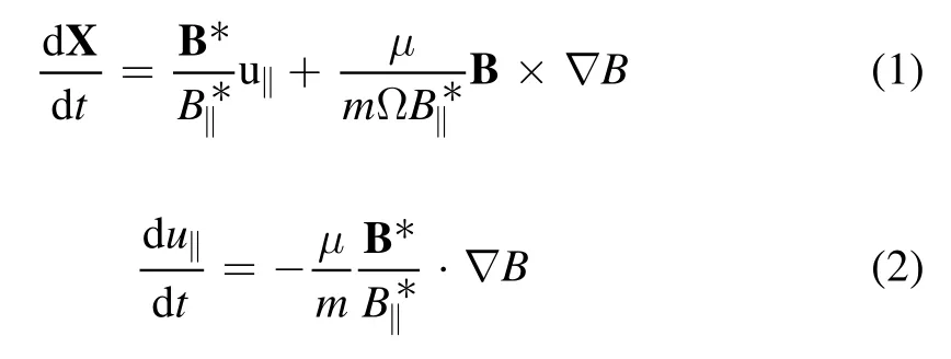
whereX is the guiding-center position,u‖is the parallel (to the magnetic field) velocity, Ω =BZe/mis the cyclotron angular frequency, and m and Ze are the mass and charge of the particle,respectively.B is the magnetic field,andμis the magnetic moment defined byμ=(2B)with⊥ubeing the perpendicular speed.B* andare defined by

where b = B /B.If we use the approximation≈B,then equation (1) is written as
In order to follow particles outside of the Last-Closed-Flux-Surface (LCFS), we use the cylindrical coordinates(R,φ,Z) rather than the magnetic coordinates in integrating the above equations of motion.This guiding center code is the TGCO code, which is originally developed to simulate NBI deposition and compute the initial beam ion distribution [21, 22].
3.Simulation parameters
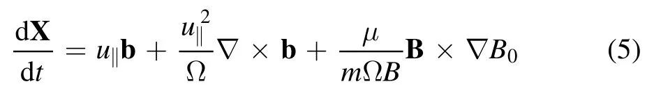
The EAST tokamak is a full superconducting tokamak device with a D-shaped poloidal cross-section and advanced divertor configuration, which has a major radius R = 1.85 m and a minor radius a = 0.45 m.Its elongation ratio k = 1.2–2,maximum plasma current Ip= 1 MA, and maximum designed center toroidal field strength Bt= 3.5 T.The EAST equilibrium used in this paper is reconstructed by the EFIT code [23] based on the shot #62585 of EAST tokamak at 3.8 s, where the injected ICRF power is about 1.0 MW and central magnetic field is 2.3 T.The central electron temperature, ion temperature and electron density are 1.76 keV,1.5 keV and 5.5 × 1013cm-3, respectively.The flux surfaces of the equilibrium and simulation region are plotted in figure 1(a).In our calculations,the initial location of fast ions is chosen to be located near the magnetic axis, but symmetrical in toroidal direction, as shown in figure 1(b).This is consistent with the results of figure 4 in [19], where it is shown that the resonance layer of the H ions is located near the magnetic axis.In the resonance layer, the fast ions are uniformly loaded in the configuration space.The corresponding velocity distribution of the fast ions produced by ICRH is modeled by the bi-Maxwellian distribution [17],which takes the following form:
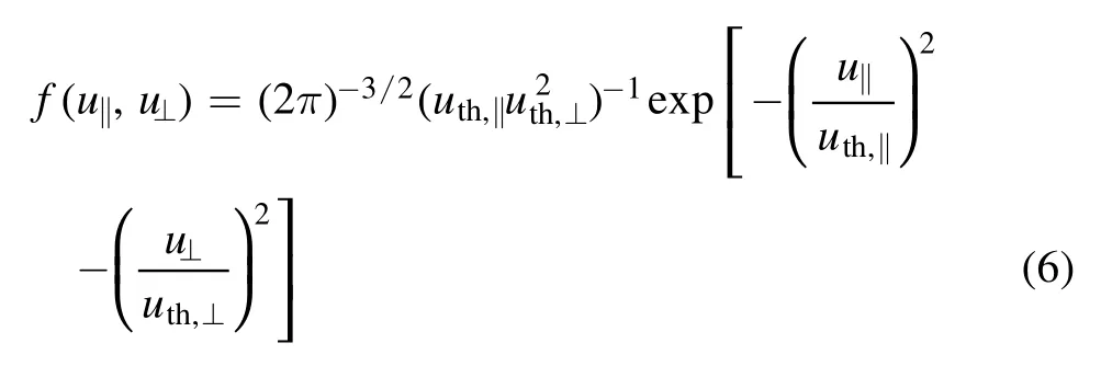
Figure 1.(a) Flux surfaces shape of EAST discharge #62585 at 3.8 s.The red dashed rectangle is the simulation region on the poloidal plane used in the simulation.(b) The hashed region represents the initial location of fast ions,namely the location of the ion cyclotron layer(1.84 m to 1.94 m in the R direction,−0.61 m to 0.73 m in the Z direction).A, B and C signify the upward region,middle region and downward region in the cyclotron layer,respectively.
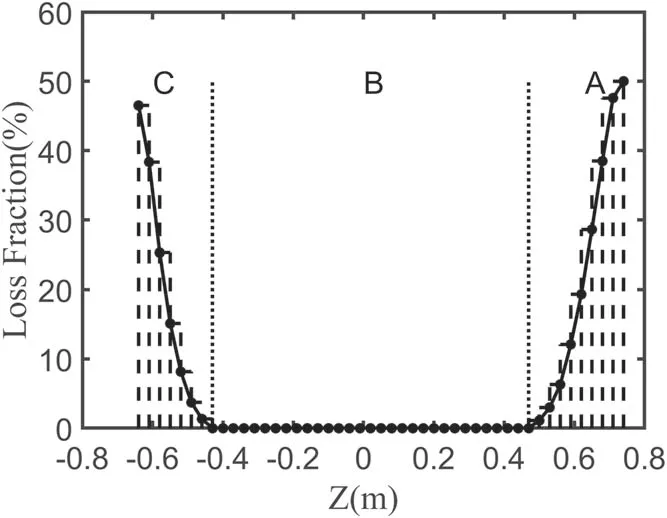
Figure 2.The dependence of the loss fractions of fast ions on position Z in figure 1(b).
4.Simulation results and discussions
Figure 2 shows the dependence of the loss fractions of fast ions on position Z in figure 1(b),from which it is obvious that there are three regions existing in the resonance region.In the middle region B, the loss fraction of fast ions is very small(below 1%), while at both ends of the heating layer, the loss fractions of fast ions increase very quickly.In other words,the loss of fast ions produced by ICRH mainly appears at both ends of the resonance region, namely the A and C regions.It is known that the fast ions in the tokamak produced by auxiliary heating systems can be divided into two types of ions at least,namely trapped ions and passing ions.In order to determine which region of phase space the lost ions come from, an additional calculation is carried out.The results show that about 72.46% of fast ions loss comes from the trapped region, and 27.54% of fast ions loss comes from the passing region.Figure 3 shows these two ways that fast ion loss can occur to the first wall with changing initial position in the A region.Figure 3(a) shows the way in which a passing ion orbit can transition to a lost ion orbit,where the energy of the fast ion is 40 keV and the pitch angle is 130 degrees.When the initial location of a fast ion is located at (1.93 m,0.61 m), the projection of fast ion orbits onto the poloidal plane is approximately elliptical,which suggests that this fast ion is a typical passing ion; see the blue line in figure 3(a).However, when the initial location of the fast ion is changed to (1.93 m, 0.64 m), the fast ion drifts out of the outmost closed magnetic surface and is lost to the first wall;see the red line in figure 3(a).Figure 3(b) shows the way in which a trapped ion orbit transitions into a lost ion orbit, where the pitch angle is 100 degrees and the energy of fast ion is also 40 keV.When the initial position of the fast ion is located at(1.92 m, 0.58 m), the corresponding fast ion orbit projection onto the poloidal plane is a banana orbit,which indicates that this fast ion is a trapped ion; see the blue line in figure 3(b).However, when the position of the fast ion is changed to(1.92 m,0.61 m),the fast ion also turns into a lost ion;see the red line in figure 3(b).
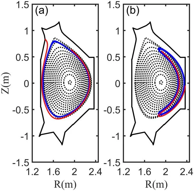
Figure 3.(a) Guiding center orbits of a marginally confined passing ion (blue) and a lost passing ion (red).(b) Guiding center orbits of marginally confined trapped ion (blue) and lost trapped ion (red).
In this subsection,we plan to answer the question of why the loss fraction of fast ions increases so much with changing the initial locations of fast ions in the A and C regions in figure 2.For simplicity, once the fast ion drifts out of the outmost closed magnetic surface, it is regarded as a lost ion.For the passing ions, the drift displacementdphas the following form [25]:
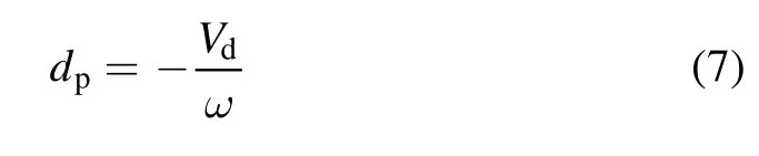
whereωis the poloidal transit frequency,andVdis the vertical drift due to the gradient and curvature of the toroidal field.Substituting the concrete expressions ofωandVdinto equation (7), we can obtain
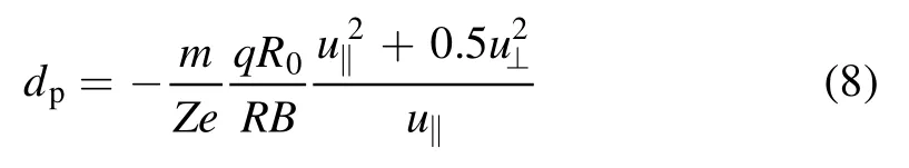
where R is the major radius,R0is the major radius at magnetic axis, and q is the safety factor.Using the conservations of energy and magnetic moment,the equation(8)can be further expressed as
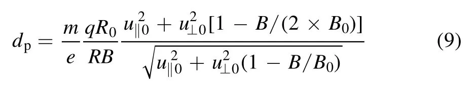
whereB0,u‖0andu⊥0are the magnetic field,parallel velocity and perpendicular velocity at the initial location,respectively.Figure 4 shows the contours of the drift displacementdpin the heated layer in figure 1(b), together with the boundary of passing and trapped ions and the contours of the fast ion number density.It is obvious that the drift displacements of most passing ions are smaller than 0.02 m; only a few of the passing ions can drift to 0.08 m.So when the initial locations of fast ions are located in the B region (the distance between locations of fast ions and the outmost magnetic surface is larger than 0.09 m) in figure 2, few passing ions are lost.Another important characteristic in figure 4 is that the number density of passing ions decreases rapidly with the increase of the drift displacement.Accordingly, the closer the initial locations of fast ions approximate to outmost magnetic surface, the more passing ions will drift out of the outmost magnetic surface and be lost to the first wall.
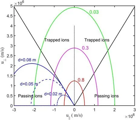
Figure 4.The drift displacement of passing ions dp in the heated layer in figure 1(b), together with the boundary of passing and trapped ions and the distributions of fast ion number density.The red, magenta and green curves are distribution function f contours.The blue curves denote drift displacement of passing ions.
For trapped ions,the drift displacementdtcan be written as follows [25]:
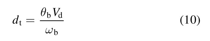
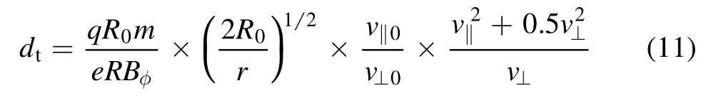
where r is the minor radius of the flux surface.Using the conservations of energy and magnetic moment, the equation (11) can be further expressed as

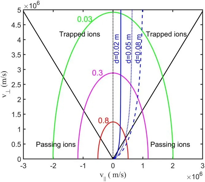
Figure 5.The drift displacement of trapped ions dt in the heated layer in figure 1(b), together with the boundary of passing and trapped ions and the distributions of fast ion number density.The red, magenta and green curves are distribution function f contours.The blue curves denote the drift displacement of trapped ions.
To further confirm the result that the loss of fast ions produced by ICRH mainly appears at both ends of the resonance layers, the loss of fast ions between the other two resonance layers are simulated; see figure 6.Figure 6(a)shows the initial location of two resonance layers.The dependences of the loss fractions of fast ions in these two resonance layers on position Z are shown in figures 6(b) and(c), respectively.It is clear that three regions just like the regions in figure 2 can be found.The loss of fast ions in the middle region is very small, while in the other two regions,the loss fractions of fast ions increase very quickly with changing Z.It is worth noting that both the widths of the middle region in figures 6(b) and (c) are less than that in figure 2,where the width of the middle region is about 0.9 m.This implies that the fast ion loss in the resonance layer in figure 2 may be smaller than those in the resonance layers in figures 6(b) and (c).To prove this conclusion, the mean fast ion loss fractions in these three cases are calculated.The calculations show that the mean fast ion loss fractions in figures 2, 6(b) and (c) are 1.27%, 5.59% and 1.47%,respectively.Thus, controlling the location of the resonance layer near the magnetic axis may be more conducive to the EAST tokamak ICRH operation.In addition, we should note that controlling the resonance layer in the central region is motivated more by the need to produce centrally peaked bulk plasma temperature profiles than the requirement of minimizing fast ion losses.

Figure 6.(a)The initial location of two resonance layers.The left resonance layer corresponds to 1.62 m to 1.72 m in the R direction,and the right resonance layer corresponds to 2.07 m to 2.17 m in the R direction.(b)and(c)show the dependence of the loss fractions of fast ions on position Z.

Figure 7.(a)Initial locations of the fast ions.(b)Temporal evolution of the fast ion loss fraction.(c) Loss distribution of the fast ions(poloidal view).(d) Loss distribution of the fast ions (top view),where A and B represent the locations of the NBI heating system and ICRF heating system, respectively.
Since the loss of fast ions appears, then the questions about where the lost fast ions are and how big the loss fraction is become very important.In order to answer these questions,we simulated the loss of the fast ions in the A and C regions,respectively.The loss information of fast ions in the A region is shown in figure 7.Figure 7(a) gives the initial locations of fast ions, where the fast ions are located in the A region(1.84 m to 1.94 m in the R direction;0.47 m to 0.73 m in the Z direction) in figure 2.Figure 7(b) shows the temporal evolution of the fast ion loss fraction,from which we can find that the loss fraction is about 13.3%.The corresponding loss distributions of fast ions are plotted in figures 7(c) and (d).Figure 7(c)shows the poloidal distribution of lost fast ions on the first wall,from which it can be found that the fast ions are mainly lost where the Z is below 0.The detailed simulation shows that about 93.4% of fast ions are lost in Z < 0, and about 85.2% of fast ions are lost near the midplane.Figure 7(d)shows the toroidal distribution of lost fast ions on the first wall.It is clear that the loss of fast ions is almost uniformly distributed between the windows.Figure 8 shows the loss information of C region fast ions.Figure 8(a) gives the initial locations of fast ions,where the fast ions are located in the region(1.84 m to 1.94 m in the R direction;−0.64 m to−0.43 m in the Z direction),corresponding to the C region in figure 2.Figure 8(b) shows the corresponding temporal evolution of the fast ion loss fraction.The loss fraction of fast ions is about 13.79%,which is marginally higher than the loss of the A region.Figures 8(c)and(d)show the distributions of lost fast ions on the first wall.Similar to distribution in figures 7(c) and (d), the fast ions are also mainly lost in the region Z < 0 in the poloidal direction, and almost uniformly in the toroidal direction.However,it should be noted that the loss of the fast ions in the poloidal direction is closely related to the toroidal magnetic field.When we make the toroidal magnetic field reverse, the loss of the fast ions will mainly occur at the region Z > 0 in the poloidal direction.Similarly,most of the fast ions are lost near the midplane.Hence,it can be concluded that the fast ions are mainly lost near the midplane.The lost regions for typical particles are shown in the appendix, see figures A1 and A2.
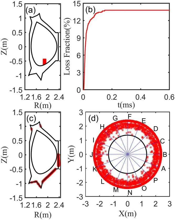
Figure 8.(a)Initial locations of the fast ions.(b)Temporal evolution of the loss fraction.(c) Loss distribution of the fast ions (poloidal view).(d)Loss distribution of the fast ions(top view),where A and B represent the locations of the NBI heating system and ICRF heating system, respectively.
It is well known that the ICRH power is mainly coupled into the perpendicular motion of fast ions through waveparticle resonance, while the parallel motion of fast ions is essentially independent of ICRH.In other words, there is a positive correlation between the ICRH power and the ratio of perpendicular speed to parallel speed of the fast ions producedby ICRH.Based on this conclusion, the effects of ICRH power on the loss fractions of fast ions can be studied by scanning the ratio of perpendicular speed to parallel speed of the fast ions, namely theC⊥/C‖in our simulation.Table 1 shows the loss fractions of the fast ions for different ratios of⊥C/C‖and different regions, where other parameters are identical to the parameters in figure 2.It demonstrates that the loss fractions of the fast ions for both the A region and C region increase with increasingC⊥/C‖(or ICRH power),while the loss fraction of fast ions in the B region (about−0.43 m to −0.47 m in Z direction) is almost unaffected.These phenomena can be explained as follows.In the B region the distance between the locations of fast ions and the outmost magnetic surface is so large that few fast ions can drift out the outermost magnetic surface.Thus the loss fraction of fast ions in the B region is barely affected by increasing the ICRH power.However, at both ends of the resonance region, with the increase of ICRH more fast ions will turn into trapped ions,which results in the increase of fast ions loss because the loss of the fast ions mainly comes from trapped ions, as described above.
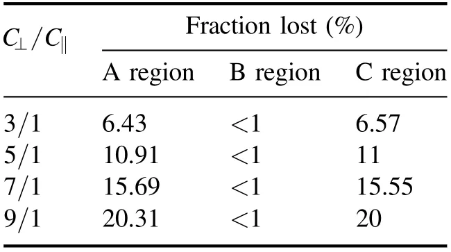
Table 1.The loss fractions of fast ions for different C⊥ /C‖.

Figure A1.Examples for typical particles loss orbit in the A region.
5.Conclusions
The loss of fast ions produced by minority ICRH in EAST is numerically investigated by a guiding center orbit following code.The fast ion loss produced by ICRH is found to appear mainly at both ends of the resonance layer,while the fast ion loss of the middle region in resonance layer is very small.This is because the drift displacements for most of the fast ions are relatively small, and only a few of the fast ions can drift to 0.08 m.Thus, the fast ion in the middle of the resonance layer cannot drift out of the outermost closed magnetic surface and turn into a lost ion.Both the passing ions and trapped ions can turn into lost ions.However, most of lost ions come from the trapped ions rather than the passing ions.The larger drift displacements of trapped ions than passing ions are the main cause of this phenomenon.The corresponding distribution of lost ions is also studied, which shows that the fast ions are mainly lost near the midplane in the poloidal direction, while almost uniformly in the toroidal direction.In addition,the fast ion losses in different resonance layers are studied.It is shown that controlling the location of the resonance layer at the plasma core may be more conducive to the EAST tokamak ICRH.Moreover,the effects of ICRH power on the fast ions loss are investigated.The results show that the loss fraction of fast ions at both ends of the resonance region increases with the ICRF power, but barely affects the loss of fast ions in the middle region.Since the reduction of the heat load is unique to each device, the results reported here may be beneficial for EAST to optimize the ICRH resonance position.
Acknowledgments
The numerical computations were performed on the ShenMa High Performance Computing Cluster in the Institute of Plasma Physics, Chinese Academy of Sciences.This work is supported by National Natural Science Foundation of China(No.11805239), and the Natural Science Foundation of Hunan Province (No.2019JJ50011).
Appendix.The lost region for typical particles.
The lost regions for typical particles are shown in the below figures,from which we can find that the lost points can appear on both sides of the upper and lower divertors, and the midplane.However, it is hard for the particles to be lost on the inner side wall.For example, when a 40 keV fast ion is located at(1.93 m,0.64 m)with a 130 degree pitch angle,the fast ion is lost to the left of the upper diverter.When the location of a fast ion is(1.92 m,0.61 m),the energy of the fast ion is 10 keV,and the pitch angle is 120 degrees,the fast ion is lost to the right of the upper diverter.
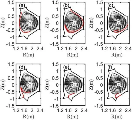
Figure A2.Examples for typical particles loss orbit in the B region.
 Plasma Science and Technology2021年11期
- Plasma Science and Technology的其它文章
- Spatial and temporal evolution of electromagnetic pulses generated at Shenguang-II series laser facilities
- Machine learning of turbulent transport in fusion plasmas with neural network
- Observation of coherent mode induced by a molybdenum dust on EAST
- Investigation of stimulated Raman scattering in longitudinal magnetized plasma by theory and kinetic simulation
- The influence of magnetic field on the beam quality of relativistic electron beam long-range propagation in near-Earth environment
- Regulation of the density distribution of a strongly dissipative plasma by a pulsed magnetic field