
The influence of magnetic field on the beam quality of relativistic electron beam long-range propagation in near-Earth environment
2021-11-30 08:28JianhongHAO郝建红XiWANG王希FangZHANG张芳QiangZHAO赵强JieqingFAN范杰清BixiXUE薛碧曦andZhiweiDONG董志伟
Plasma Science and Technology 2021年11期
关键词:赵强
Jianhong HAO (郝建红), Xi WANG (王希),, Fang ZHANG (张芳),Qiang ZHAO (赵强), Jieqing FAN (范杰清), Bixi XUE (薛碧曦), and Zhiwei DONG (董志伟)
1 North China Electric Power University, Beijing 102206, People’s Republic of China
2 Institute of Applied Physics and Computational Mathematics,Beijing 100094,People’s Republic of China
Abstract In recent years, it has been proposed to use satellite-mounted radio-frequency (RF) accelerators to produce high-current relativistic electron beams to complete debris removal tasks.However,when simulating the long-range propagation (km-range) process of the electron beam, it is difficult to directly use the particle-in-cell method to simultaneously consider the space charge effect of beam and the influence of the geomagnetic field.Owing to these limitations, in this paper,we proposed a simplified method.The ps-range electronic micropulses emitted by the RF accelerator were transmitted and fused to form a ns-range electron beam; then, combined with the improved moving window technology,the model was constructed to simulate the long-range propagation process of the relativistic electron beam in near-Earth environment.Finally, by setting the direction of movement of the beam to be parallel,perpendicular and at an inclination of 3°to the magnetic field,we analyzed and compared the effects of the applied magnetic fields in different directions on the quality of the beam during long-range propagation.The simulation results showed that the parallel state of the beam motion and magnetic fields should be achieved as much as possible to ensure the feasibility of the space debris removal.
Keywords: space debris, relativistic electron beam, long-range propagation, geomagnetic field,radio frequency accelerator
1.Introduction
With the continuous development of space exploration technology,the potential risks caused by space debris orbiting the Earth have become increasingly prominent [1–3].Among them, centimeter-scale debris from 1 to 10 cm in size are called most dangerous space debris, because neither active evasion nor structural protection can be used when dealing with them.How to effectively remove centimeter-scale debris that threatens space security has become an area of interest.Recent years, tether or net systems for space debris capture have become an important area of research.However, given the high technical requirements in its operating range and accuracy,the related control issues of system stability are still under further study [4].In addition, high-power laser technology research for the destruction of space debris has been going on for many years.Fang et al [3] proposed a spacebased nanosecond pulse laser to remove centimeter-scale debris near the International Space Station, but there are still some problems with this technology that need to be solved such as low energy conversion efficiency.Currently, the development of high-power pulse technology has made it feasible for spacecraft to generate MeV-range relativistic electron beams.Furthermore, three-dimensional particle-incell (PIC) simulation conducted by Gilchrist et al in 2004 shows that relativistic beams are more stable than low energy during the emission of a spacecraft [5], and can also produce large impulse to burn or knock space debris off the original orbit when comes into contact with them.Therefore, highcurrent relativistic electron beam is considered to be a new tool to remove centimeter-scale debris, and this idea is expected to enter the conceptual research stage and then become a competitive space debris processing technology in the future.
At present, the advent of high-power, low-voltage radiofrequency (RF) amplifier chips has enabled the development of new electron linear accelerator technologies.The accelerator no longer needs to be powered by a heavy high-voltage accelerator to power the entire device, but is coupled to its own lightweight and compact amplifier, besides, the RF accelerator can accumulate enough energy for a long period of time and emit pulses in a short period to achieve highenergy and high-current emission.Therefore, it is more suitable to use spaceborne RF accelerators to launch relativistic electron beams into space [6].Los Alamos National Laboratory, SLAC and Goddard Space Flight Center have been cooperating for many years to develop a space RF electron accelerator intended for installation and operation on satellites.At present,a more compact,lighter and more robust radio frequency electron accelerator has been developed and the emitted electron energy can reach the order of MeV [7].The article took this as a point of departure to make a preliminary theoretical exploration of the long-range propagation of ‘micropulse’ electron beam.For the purpose of realizing the numerical simulation of long-range propagation of tens of kilometers,the high-energy electronic micropulses(ps-range)with periodic structure emitted by the compact RF electron accelerator were generated and fused into a long electron beam pulse (ns-range).Afterwards, we combined improved moving window technology to establish a propagation model,and finally explored the influence of magnetic fields in different directions in the near-Earth environment on the longrange propagation process of the ns-range relativistic electron beam and its beam quality.
2.Fusion of micropulse relativistic electron beams
2.1.RF accelerator and micropulse relativistic electron beam of ps-range
Relativistic electron beams produced by the compact satellitemounted RF accelerator have a periodic structure with various time and length scales.The smallest scale structures are called‘micropulse’that are synchronized with the RF cycle.During the propagation process, multiple micropulses will fuse to form a ‘long pulse’ due to the free expansion caused by the emittance,energy spread and space charge effect.The launch time of each ‘micropulse’ and the time required for ‘fusion’comprehensively depend on the structure of the accelerator,the spacecraft power limitations,and the scientific goals of the task, etc [8].
Taking into account the self-weight and volume limits of the spaceborne RF accelerator in the near-Earth environment,the minimum size of‘micropulse’emitted by the compact RF electron accelerator is ps-range when simulating the space debris removal task.The specific parameters of electron beam are shown in table 1, and its initial distribution of time and velocity phase space are both set to double Gaussian truncation.

Table 1.Physical parameters of the reference relativistic electron beam.
2.2.Fusion of micropulses—formation of ns-range long pulse
According to table 1, the ps-range micropulse emitted by the compact RF accelerator has a small axial size.When using the PIC method for propagation,in order to better distinguish the size expansion caused by the space charge force and the influence of the near-Earth magnetic field on the beam quality during the propagation process, high requirements are put forward on the size and quantity of the space grid, which is difficult to achieve long-range propagation simulation on the order of 10 km.Actually, the initial structure of the ps-range micropulse (radial size is much larger than the axial one)determines that the space charge effect has a greater impact on the free expansion of the axial direction during the propagation process,and the initial energy spread of the micropulse is also mainly concentrated in the axial direction.Therefore,under the combined action of the two effects, the micropulse will complete the fusion of multiple pulses in the axial direction and form a ‘long pulse’ (ns-range) at the initial propagation stage after launch (km-range), as shown in figure 1.Compared with the propagation task of electron beams of tens of kilometers in the near-Earth environment,the multi-pulse fusion process only accounts for a few tenths or less of the whole process, and the impact on the propagation results is very limited,almost negligible.Based on this physical process and taking into account the limitation of psrange micropulse’s long-range propagation simulation, this section adopted an approximate treatment.By respectively simulating the fusion process of ps-range micropulse and the long-range propagation process of fused long pulses(ns-range)in a magnetic field environment,we finally achieved the long-range propagation simulation of tens of kilometers,and then explored the influence of different magnetic field environment on the relativistic electron beam quality.
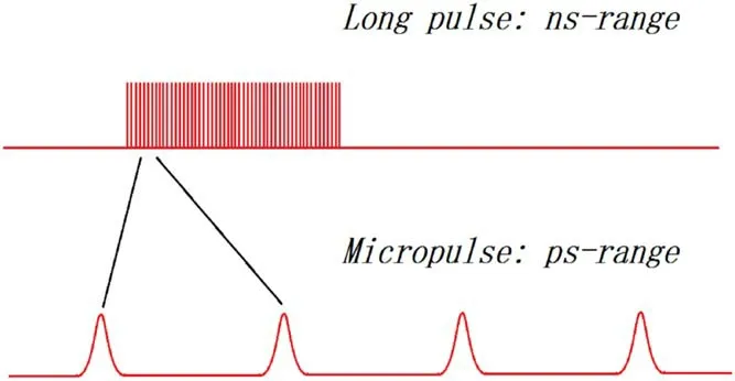
Figure 1.Fuse process.
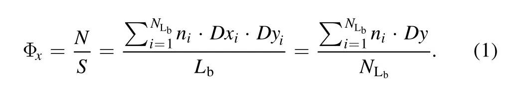
Take the fusion process of two micropulses as an example, given that the distance and time-consuming of the fusion process are very short, this process ignores the influence of magnetic field and is considered as a vacuum environment.The shape change of beams before and after the fusion is shown in figure 2.In addition, due to the change of pulse shape and size during the fusion process, the beam quality such as fluence and current intensity change accordingly.The calculation formula for the fluence φxinside the beam is shown in equation (1), whereDxiandDyiare respectively the sizes of the axial and radial grids in PIC method;ni,Lb,NLbare the charge surface density per grid inside the beam,the axial size of the beam and the number of space-grids included in the axial direction of the beam,respectively.
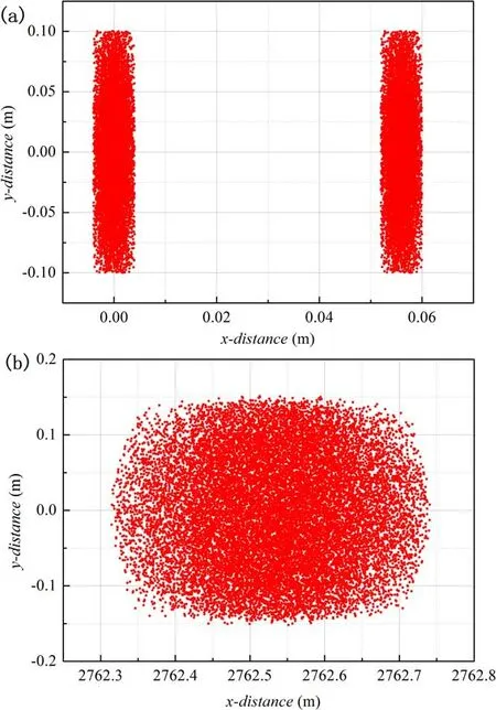
Figure 2.The shape change diagram of micropulse.(a) x = 0 m,(b) x = 2.7 km.
According to equation(1),the fluence distributions of the beam before and after the fusion are shown in figures 3(a)and(b),where the ordinate is the axial fluence value of the beam,and the abscissa is the number of radial grids in the calculation space of the moving window.Comparing the two pictures,the change of the fluence distribution demonstrates that during the fusion process of micropulses into long pulses,affected by various physical factors (such as energy spread and emittance), the beams gradually tend to be evenly distributed from the initial double Gaussian truncated distribution.In addition, due to the change of pulse size and duty cycle, the current intensity of the beam after fusion also reduces accordingly.
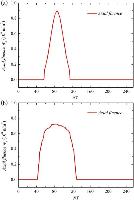
Figure 3.Changes in the fluence distribution of the beam.(a)Before the fusion, (b) after the fusion.
3.Long-range propagation model of relativistic electron beam
3.1.Improved moving window technology
The traditional moving window technology selects calculation window with a reasonable size, and allows it to move with the beam at the highest speed close to lightspeed.At every moment, only the current transmission area of the particle beam is discretely divided, and only the current transmission result of the particle beam is calculated and retained[9].Finally,the long-range propagation(km-range)is achieved by connecting every short-range windows and then restoring the overall simulation, which can significantly reduce the size of the calculation space and improve the calculation efficiency without affecting the overall physical process.
During the long-range propagation in the near-Earth environment,the relativistic electron beam will be affected by the geomagnetic field and then appears centroid deflection.Besides,the initial energy spread,emittance and space charge effect of the beam will cause obvious dispersion in all directions, therefore, this work adopted an improved moving window technology, set the radial and axial electric field boundaries as periodic boundaries and open boundaries,respectively, and set the particle boundaries as absorbing boundaries, so that the calculation window adjusted its position with the centroid deflection, and adjusted the size with the dispersion of the beam, so as to achieve a more accurate simulation of the propagation process and further improve the accuracy and efficiency of calculation [8].
3.2.Long-range propagation model
When taking the above-mentioned ns-range relativistic electron beam for long-range propagation simulation in a near-Earth environment, given that it is different in axial direction from infinitely long electron beam (the pulse has an energy spread), this process considered not only the influence of emittance, space charge effect and the geomagnetic field, but also the change in beam quality due to the dispersion caused by energy spread [10].
The PIC method is one of the important tools for studying the motion of charged particle [11].Besides the application of the moving window technology, in order to effectively avoid the excitation of high-frequency noise and oscillation, and save the calculation space required for such reactions to improve efficiency, the ‘quasi-electromagnetic model’ is adopted.On the basis of the PIC electrostatic model, the self-generated magnetic field and the external magnetic field were applied to the beam in a self-consistent manner, and the long-range propagation model of the relativistic electron beam was established [12, 13].This model set up a two-dimensional sheet beam for long-range propagation along the x direction in a two-dimensional space and threedimensional velocity (2D3V) coordinate system, as shown in the figure 4.
Figure 4.The geometry of simulation model.
Since this section used a two-dimensional sheet beam with a highly symmetrical structure and a significantly larger axial size than the radial for simulation,during the long-range propagation process, for any beam density distribution, the relationship between the self-generated electric field component and the magnetic field component always satisfied equation(2)[10],therefore,the model first solved the Poisson equation (3) to obtain the radial component of the self-generated electric fieldEyat each side of the grid in the calculation space,and then obtain the self-generated magnetic fieldBzby equation (2) [13, 14].

whereρ,ψ,β,care respectively the charge density, electrostatic potential at each node of the grid, relativistic factor and lightspeed;Bzis the z-direction component of the induced magnetic fieldBg.
Given the influence of the geomagnetic fieldBain the near-Earth environment, the form of the total external magnetic field that is self-consistently acting on the beam propagation process is shown in equation (4)
4.Simulation and analysis of the long-range propagation of electron beams when considering the geomagnetic field
In the near-Earth environment, when the long-range propagation of the relativistic electron beam is applied to execute the task such as space debris removal, in order to ensure that the beam can accurately aim at the target and have sufficient impulse, the influence of the geomagnetic field cannot be ignored [15, 16].Satellite space tasks usually set their orbital plane around the equator to achieve an ideal state in which the direction of its movement is parallel to the Earth’s magnetic field.However, in practice, taking into account the influence of various factors, a movement completely parallel to the magnetic field is difficult to achieve.Most satellites move in a small angle with the magnetic field.Therefore,from the perspective of the propagation of the relativistic electron beam emitted by the spaceborne accelerator,in order to explore the influence of the geomagnetic field on the beam quality during propagation, this section simulated the geomagnetic environment of a near-Earth satellite orbit (B=5 × 10⁻⁵T), and respectively considered three cases, namely the extreme cases where the movement direction of the relativistic electron beam is parallel or perpendicular to the direction of the magnetic field,and the general case where the two directions are at an angle of 3°; then analyzed the changes in the beam quality under the magnetic field in different directions, including centroid deflection, shape change and fluence rate distribution, etc.
4.1.Parallel magnetic field
When the movement direction of the beam is parallel to the magnetic field (Bx= 5 × 10⁻⁵T), the applied magnetic field will not generate Lorentz force on the beam,thus the process is similar to the process in vacuum with no centroid deflection.In vacuum, the beam continuously diffuses in axial and radial directions due to the influence of emittance,space charge effect and the initial energy spread, resulting in a decrease in the particle density and fluence rate inside the beam.However, in the case of the parallel magnetic field, theBxwill provide an additional radial pinch force to the beam to suppress its radial expansion, which significantly slows down the change of the beam size, so its rate of decrease of fluence rate should be lower than that in vacuum.The fluence rate distributionφat each moment in the beam propagation process is calculated by equation (5), wherevx,Rbare respectively the axial velocity and radial size of the beam,NRbis the number of space-grids included in the radial direction of the beam, and the other parameters are all the same as equation (1)

Figures 5 and 6 respectively show the fluence rate distribution of the beam during 10 km propagation under vacuum and paramagnetic condition.Comparing the two pictures, it is clear that the decrease in fluence rate in the paramagnetic case is significantly smaller than that in the vacuum when the beam is propagated to the same distance.Therefore, when a relativistic electron beam is applied to remove space debris in a near-Earth environment, the parallel magnetic field can effectively suppress the radial expansion of the beam, and ensure the focus of the beam to a certain extent, which can increase the beam-to-target impulse (compared to the vacuum condition) and is conducive to task completion.
Figure 5.Change of beam fluence rate under vacuum.
Figure 6.Change of beam fluence rate under the parallel magnetic field.
4.2.Vertical magnetic field
When the movement direction of the beam is perpendicular to the geomagnetic field (Bz= 5 × 10⁻⁵T), the electrons will deflect under the influence of Lorentz force.Under the background of the near-Earth environment, the meter-scale beam in size can be regarded as a mass point,and the centroid deflection of it is analyzed.The theoretical deflection radius of the relativistic electron with an energy of 10 MeV is shown as equation (6)

The centroid trajectories of the beam obtained by theoretical formula and numerical simulation are shown in figure 7.The black solid line is the trajectory obtained by simulation which closely match the theoretical result (calculated by equation(6),as shown by the red dotted line).However,from the perspective of space debris removal task, in a vertical magnetic field environment, the propagation trajectory of electron beam is approximately a circular, so in this case the beam cannot move forward in the near-Earth environment to complete the removal task.
The following analyzes the changes in the beam quality during the propagation of the beam in the vertical magnetic field environment.During the advancement of the beam, the electrons at the head and end are accelerated and decelerated by the forward electrons, respectively; according to equation (6), the deflection radii of them are different,therefore, the beam is twisted in the radial direction, and its shape changes to ‘lower at head and higher at end’.Simultaneously, the shape change leads to an increase in the radial size of the beam, which accelerates the decrease speed of beam’s fluence rate.In conclusion, during the propagation process, on one hand, the vertical magnetic field will cause the Lorentz deflection of the beam,which makes it unlikely to carry out the long-range propagation(km-range);on the other hand,it will also deform the beam due to the position change of the internal particles, then accelerate the decrease of the fluence rate, and weaken the beam-to-target impulse.
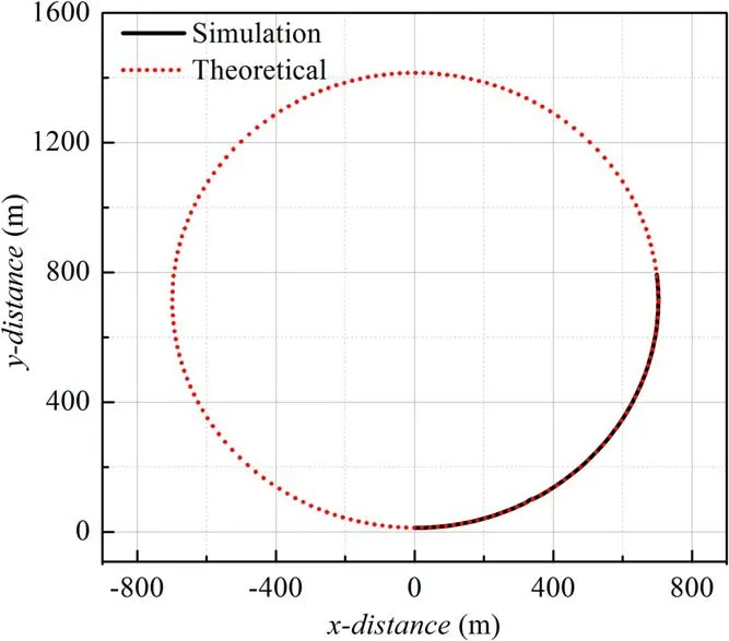
Figure 7.Centroid deflection trajectory of the beam under vertical magnetic field.
4.3.Magnetic field with a 3° angle
In the actual near-Earth environment, based on the complex structure of the geomagnetic field and the influence of various space factors on the satellite movement,the more common state is that there is a certain inclination between the direction of the satellite movement or the launching of the spaceborne electron beam and the direction of the geomagnetic field, rather than absolutely parallel or perpendicular.In this section,the changes of beam quality in the long-range propagation process were analyzed by taking a more universal situation that the beam movement direction and the magnetic feild(5 × 10⁻⁵T)direction are at an angle of 3°.The magnetic field is shown in equation (7)
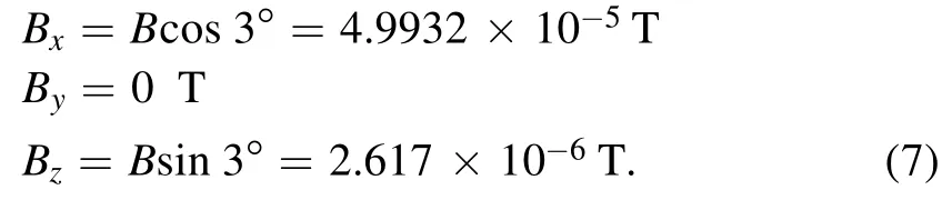
Similarly, the beam is regarded as a mass point in the near-Earth environment, and it will undergo Larmor precession under the combined action of magnetic fields in both x and z directions.However,since the 2D3V coordinate system was used in the long-range propagation model of the charged particle beam established in the third section of this paper[13, 17], the centroid deflection trajectory of the beam in the(x, y) space was obtained, which is approximately an oscillation curve, as shown in figure 8.
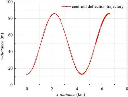
Figure 8.Centroid deflection trajectory of the beam under the magnetic field with a 3° angle.
When the movement direction of the beam is perpendicular to the geomagnetic field, the beam will appear a ‘lower first and higher end’ shape change due to the velocity distribution of internal particles.When the directions of beam and magnetic field are at a small angle,that is,when the magnetic fields in both x and z directions act on the propagation process simultaneously,the beam will appear a‘twisting phenomenon’in which the two shapes of ‘lower at head and higher at end’and ‘higher at head and lower at end’ alternately appear.Figures 9(a)and(b)show a process that the shape of the beam is ‘twisted’: when it is transmitted to about 1.4 km, the beam shows a‘low at the head and high at the end’shape(figure 9(a)shows the distribution of particles’ axial relativistic velocity and the shape of beam); then, as the transmission continues,when it is transmitted to about 1.9 km, the effect of the magnetic field causes the beam to be twisted in the opposite direction,turning it into a shape of‘high at the head and low at the end’ (figure 8(b) shows the distribution of particles’ axial relativistic velocity and the shape of beam that is opposite to figure 9(a)).In the process of beam changing from figures 9(a)to (b), its shape appears a brief critical state that is approximately same as the initial shape(approximately a rectangle,as shown in figure 10).The situation in which the beam is twisted forward and backward in turn will occur throughout the entire long-range propagation.
Figure 9.The distribution of axial relativistic velocity and changes of shape.(a) Transmitting to 1.4 km, (b) transmitting to 1.9 km.

Figure 10.The critical state of shape change(transmitting to 1.6 km).

Figure 11.Comparison of the maximum value of the beam fluence rate.
As mentioned above,in the process of beam twisting,its radial size also changes with the shape, and the changing extreme point (maximum or minimum) appears in sequence during the propagation process.The ‘critical state between two shape changes’ of beam in figure 10 can represent the state of a certain minimum value of the radial size and according to equation (5), this state also corresponds to a certain maximum value of the beam fluence rate.In the process of long-range propagation (km-range), although the radial size of the beam keeps constantly changing back and forth, when comparing its initial state and the successively appearing maximum of fluence rate, the magnitude of the fluence rate still shows a decreasing trend because of the axial dispersion caused by the initial energy spread.For example,during the propagation process,the first two maximum values of the fluence rate appeared at 1.6 km and 4.6 km, respectively.Compared them with the initial state of the beam, the magnitude of fluence rate decreased sequentially,as shown in figure 11.Therefore, according to the changing law of the beam quality in a magnetic field environment with an angle of 3°, in the ‘target-contact task’, it is necessary to accurately predict the beam’s transmission trajectory and the position of the fluence rate extremum caused by the shape change, so as to ensure the beam aiming and the sufficient beam-to-target impulse, then guarantee the completion of the task.
5.Conclusions
In recent years, with the development of high-power pulse technology and RF accelerators, the high-current relativistic electron beam is considered to be a possible method to remove centimeter-scale debris in low-Earth orbit.This article explored for this future technology from the perspective of long-range propagation of the relativistic electron beam in the near-Earth environment.Due to the limitation of particle simulation method, we used the ns-range electron beam that formed by the fusion of the ps-range micropulse launched by the RF accelerator,combined with the PIC electrostatic model and improved moving window technology to establish a longrange propagation model of the relativistic electron beam.Then we simulated the electron propagation process under three cases (the movement direction of the electron beam is parallel or perpendicular to the direction of the magnetic field;and two directions are at an angle of 3°),and finally analyzed the change of beam quality during these processes.The results of study can be summarized as follows.
(1) In the case of paramagnetism, the applied parallel magnetic field will not change the propagation trajectory of the beam, and will provide a pinch force in the radial direction to suppress the decrease of fluence rate,which can achieve the focus of the beam to a certain extent.
(2) Under the action of the vertical magnetic field, the Lorentz deflection will make the propagation unable to advance,and therefore the long-range propagation(kmrange) cannot be realized.
(3) When the movement direction and the magnetic field direction are at a small angle, the beam’s trajectory in the (x, y) two-dimensional space is an approximate oscillating curve,which means the propagation can still move forward.However,when it comes to contact tasks such as beam shooting, it is necessary to focus on the aiming problem based on its trajectory.At the same time,the twisting of the beam shape under the magnetic field will cause the fluence rate to change back and forth.In order to ensure that beam-to-target impulse is basically at the extreme point and is sufficient to complete the space task, the selection of the launch position, direction, and the prediction of the transmission orbit are all required in a high accuracy.
Therefore, comprehensively considering the influence of the geomagnetic field,in the near-Earth environment,particle emission equipment should minimize the angle between the beam movement direction and the geomagnetic field direction to make the two directions tend to be parallel, so as to more accurately grasp the motion state of beam and realize the idea of removing centimeter-range space debris, etc.
Acknowledgments
This work is supported by National Natural Science Foundation of China (Nos.61372050, U1730247).
猜你喜欢
上海工艺美术(2021年4期)2021-04-24
妇女生活(2019年12期)2019-12-16
民间文学(2019年10期)2019-11-21
上海故事(2018年8期)2018-09-06
东方艺术·书法(2018年1期)2018-04-30
爱你(2017年31期)2017-11-24
小说月刊(2017年8期)2017-08-16
微型小说选刊(2014年27期)2014-11-17
天池小小说(2009年3期)2009-04-24
数学大世界·小学低年级辅导版(2009年3期)2009-04-14
 Plasma Science and Technology2021年11期
- Plasma Science and Technology的其它文章
- Spatial and temporal evolution of electromagnetic pulses generated at Shenguang-II series laser facilities
- Numerical study on the loss of fast ions produced by minority ion cyclotron resonance heating in EAST
- Machine learning of turbulent transport in fusion plasmas with neural network
- Observation of coherent mode induced by a molybdenum dust on EAST
- Investigation of stimulated Raman scattering in longitudinal magnetized plasma by theory and kinetic simulation
- Regulation of the density distribution of a strongly dissipative plasma by a pulsed magnetic field