
Numerical studies of the influence of seeding locations on D-SOL plasmas in EAST
2022-02-15 11:07MinWANG王敏QinmeiXIAO肖青梅XiaogangWANG王晓钢andDaoyuanLIU刘道远
Plasma Science and Technology 2022年1期
Min WANG (王敏), Qinmei XIAO (肖青梅),2, Xiaogang WANG (王晓钢),2 and Daoyuan LIU (刘道远)
1 School of Physics, Harbin Institute of Technology, Harbin 150001, People’s Republic of China
2 Laboratory of Space Environment and Physics Science, Harbin Institute of Technology, Harbin 150001,People’s Republic of China
3 School of Physics, Dalian University of Technology, Dalian 116024, People’s Republic of China
Abstract Impurity seeding has been found effective for divertor detachment operations and the seeding location plays a key role in this process.In this work, we use the fluid code SOLPS-ITER to study the influence of seeding locations on divertor and scrape-off layer (D-SOL) plasmas in Experimental Advanced Superconducting Tokamak (EAST) with neon seeding.Simulation results indicate that the neon is a highly effective impurity in mitigating the heat flux and electron temperature peaks on the target of the divertor and achieving the partial detachment on both inner and outer targets.Further, by comparing results of the seeding at the private-flux region(PFR) plate (called ‘TP’ location) and the outer target (called ‘XP’ location), we find that the impurity density and power radiation for TP case are higher in core and upstream regions and lower in the divertor region than that for seeding at the XP,and the difference becomes more and more obvious as the seeding rate increases.It clearly demonstrates that the seeding at the XP location is more appropriate than at the TP location, especially in high seeding rate conditions.
Keywords: impurity seeding, detachment, SOLPS-ITER, D-SOL
1.Introduction
The control of heat loads and particle flux on the divertor target is crucial but extremely challenging for steady-state operations,particularly for high fusion power devices such as China Fusion Engineering Testing Reactor (CFETR) and International Thermonuclear Experimental Reactor (ITER)[1, 2].Those steady-state operations of fusion reactors suffer an average power load of ~ 1 0 MW · m−2on the first wall and a much higher flux on the target.Thus,one has to cut the load by a great share to decrease the plasma-wall interaction(PWI)and reduce the target electron temperature to a level of<10 eV, for lowering the erosion and extending the servicelife of target materials[3].In recent decades,impurity seeding has been found effective for energy dissipation by impurity radiation [4–6].Particularly, the radiation power can be enhanced by intense collisions between the high electron temperature plasma and impurity particles with a high radiation loss rate.Then, the heat load and electron temperature at the target can be reduced.Such methods have been substantiated in various tokamaks, with the most popular seeding impurities of nitrogen(N),neon(Ne),and argon(Ar)[7–10].However, these impurities are relatively high-Z particles which may degrade energy confinement of the core plasma and cause disruptions in the worst scenario.Therefore,the impurity transport in SOL region is very crucial for stability of the upstream plasma profiles as well as the confinement of the core plasma.The results on JET, ASDEXUpgrade, and Alcator C-Mod revealed that the radiation power of impurities was observed both inside the last closed flux surface (LCFS) and outside the separatrix [8, 11, 12].In EAST, modeling and experimental works illustrated that the impurities easily transported upstream to penetrate into the core region[10,13].Also,the location of the impurity puffing exerted a significant influence on the divertor target detachment process and its magnitude.In addition, as tungsten (W)gradually replaces the carbon (C) plasma-facing materials(PFM)in future tokamaks,its erosion and physical sputtering are dominated by impurity ions rather than deuterium ions[14–16].On the other hand, it is difficult to make a high resolution measurement on the edge for impurity radiation and transport, due to the uncertainty LCFS position.Hence,for better understanding the influence of gas seeding location on detachment process and impurity transport in D-SOL regions, simulation analysis is necessary.
In this paper, we choose Ne as the impurity, and use the lower single null (LSN) configuration of EAST for transport study.The divertor geometry,seeding locations and modeling setup are described in section 2.In section 3,we compare and analyze the influence of two locations on the detachment process and impurity transport.Then, the conclusion is summarized in the last section.
2.Modeling setup
In this work, the SOLPS-ITER code package is chosen to simulate the SOL and divertor plasma.SOLPS-ITER is a large fluid code, which is coupled with the B2.5 fluid code and the Eirene kinetic code.B2.5 mainly solves Braginskii equations for ions and electrons, Eirene is a Monte-Carlo transport code which provides the neutral transport as well as its birth and death[17–19].SOLPS-ITER and its old versions have been widely and successfully used on current and future tokamaks [2, 20–22].
The simulated cross-section of EAST is illustrated in figure 1.In the modeling, the simulation region contains the core region located between core boundary (CEI) and separatrix (SEP), the D-SOL regions, and the private flux region(PFR).The simulation mesh (including triangular meshes) is constructed by 36 cells radially, 96 cells in poloidally, as shown in figure 1.
The first impurity seeding location is chosen at the PFR plate close to the outer target plate (called the ‘TP’ location),the second location is at the lower main SOL region next to outer-target of the divertor(called the‘XP’location),as shown in figure 1.Or as described in a‘two-point’theory,the first one is in the divertor region and the second one is at the divertor region entrance [23], as shown in figure 1.The impurity seeding rate is ×M10 s20−1, where M is the intensity coefficient.The species in the simulation include deuterium atoms(D), main ions (+D ), electrons, and Ne impurities (with all charge states ofNe0−Ne10+).Since the particle radial diffusion and the thermal conductivity coefficients cannot be exactly calculated in first principle, we thus use an empirical model based on experiments to fit the density and electron temperature profiles on the outer mid-plane (OMP).For L-mode discharges, considering their slow spatial variation feature, we approximate the radial diffusion coeffciient asD⊥=1.0 m2· s−1and the thermal conductivity coeffciient asχe=χi= 1.7 m2 s− 1 in the whole region [24–28].The SOL flows are driven by the poloidal transport asymmetry due to asymmetry of the edge transport between the low-field/badcurvature and the high-field/good-curvature sides [29].Also,in the simulation the EAST LSN configuration is applied with the× ∇Bpoints toward the X-point.

Figure 1.The simulation domain with its mesh structure (triangular grid for neutral particle,orthogonal grid for ion and electron),as well as Ne seeding and gas pumping locations.
The boundary conditions in modeling are listed as follows.
2.1.Core boundary
The main plasma (D+) density: 3.0 × 10¹⁹m−3, while other species are set zero, except for the neon density which has a gas puffing source outside of the core edge.The total power flux from the core to SOL is assumed as =Psol1.5 MW.It is also assumed that the total power flux is divided equally into ions and electrons, i.e.,Psol,e=Psol,i= 0.75 MW.
2.2.Divertor target
A standard sheath boundary condition is applied.The sheath heat transmission coefficients are set: =ETe0.9 for electrons and =ETi2.5 for ions.
2.3.SOL and PFR boundaries

Figure 2.Profiles of (a) the electron density ne and (b) ion + electron temperatures at OMP with seedings at TP and XP.
The radial decay lengths for both the electron and ion temperatures are set to be 3 cm.For D+and Ne+1−Ne+10,we use the radial leakage boundary condition with Γa=αa Csa na,where the subscriptais for the ions,C as is the sound speed of the ion species;αis the leakage factor.The leakage condition presents the particles leaking out the boundary (α> 0) or recycling to main plasma as the neutral(α< 0).Here,we setαD= −0.001for D+, andαNe= −0.003for Ne ions.
In order to keep the particle balance in the simulation,we add a pumping effect in the modeling with its position being shown in figure 1.Correspondingly, the recycling coefficient is set to be 1.0 at the boundaries of the D-SOL walls,targets,and dome side of private flux regions, as well as 0.95 at the pumping duct outlet.Since the pumping is mainly for neutrals, the effect is then simulated by Eirene in the region covered by triangular cells.
3.Simulation results and discussion
To reveal the effect of impurity seeding locations on D-SOL plasmas, the comparisons between Ne seeding at XP and TP in L modes are made.The Ne seeding rate is5.0 × 1019s−1.The upstream radial profiles of the electron densityne,electron temperatureTe, and ion temperatureTiat OMP are shown in figure 2.It can be seen that, as shown in figure 2(a),compared with the no seeding case, the upstream electron density is raised at a certain position ofr−rSEP,here the subscript‘SEP’stands for‘separatrix’,by the Ne seeding.It is because that some Ne particles transported into the upstream are ionized, resulting in the electron and ion temperatures decreasing.In figure 2(b), one can also find that the ion and electron temperatures are decoupled.It is due to that the ion density is lower than the electron caused by impurity seeding,in this case,Tican be higher thanT.eFurthermore, it is interesting that the electron densities at OMP for two various seeding locations are slightly different, the slope ofnewith seeding at TP is a litter higher than seeding at XP.However,Te,sepandne,sepfor both cases at OMP are almost the same or on the same order of magnitude,which indicates that the both cases have the similar upstream conditions [23].
Moreover,the upstream profiles of the total neon density and neon ion content by percentage (figure 3(a)), as well as neon ion densities for different charge states at OMP(figure 3(b)), are shown in figure 3.Here, we call neon ions fromNe0−Ne6+as low charge states, and those from Ne7+−Ne10+as high charge states.Then in figure 3(a), it can be seen that the total neon density of the TP case is higher than that of the XP case, with a peak value difference of 6.93 × 10¹⁷m−3to8.23 × 1017m−3.The neon content in the TP case is higher than that in the XP case, as increased fromcNe,CEI,XP=1.88%tocNe,CEI,TP=2.13%upstream and fromcNe,SEP,XP=3.55%tocNe,SEP,TP=4.36%downstream,respectively.Also,it is shown in figure 3(b)that the upstream density of the high charge state is much higher than that of the low charge state, due to the high electron temperature upstream.However, thenNeof the TP case at upstream is higher than that of the XP case, due to different features of flows in SOL and PFR regions[15,29].The TP location is in the PFR region,and the most of Ne ions from the TP location move along the magnetic field line to the X-point, and then enter the core boundary and further into the upstream core plasma.Oppositely,the XP location is in the SOL region,and more Ne ions transport along the magnetic field line to the outer target,thus the neon impurities are mostly concentrated in the divertor region.Hence,in order to keep a low impurity concentration in the core plasma,seeding in the XP location is a better option according to our simulation results.
Figure 4 presents the downstream profile ofne,Te,and the heat load on the outer and inner divertor targets with the two different seeding locations.It can be seen that, with Ne seeding, both targets achieve the partial detachment.However,theneandTepeaks shift to the far SOL region because the vertical shape of the divertor causes a low neutral density, as shown in figure 4 [30].Thus, in the far SOL region,both targets are still in an attached state.On the outer target,Te<5 eV withinr−rSEP<0.01 m for the XP case.For TP case on the other hand, the detachment region is much narrower (r−rSEP<0.001 m).In other words, compared with the TP case,seeding at XP locations has higher density and radiation power loss for the neon impurity.
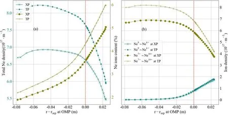
Figure 3.(a)The total neon density(solid and dashed curves in teal)and the impurity content(plus and dot curves in olive),(b)the neon ion densities of different charge states at OMP, for seedings at TP and XP respectively.
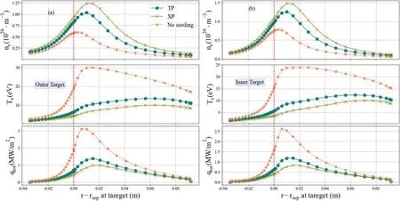
Figure 4.The electron density and temperature n e, Te ,and the heat load qtot at the outer(a)and the inner(b)targets,with seedings at XP and TP respectively.
Furthermore, profiles of the total neon and low charge states densities at the outer target are shown in figure 5, for seedings at two locations respectively, the low charge states are mainly concentrated in the divertor region due to the low electron temperature there.It can be clearly seen that, at the outer target,the total neon density,as well as the low charge states densities of the XP case, is larger than that of the TP case.As learned from these results, for seeding at the XP location, the density and radiation power of the neon are higher, while the electron temperature and the heat load at the target are lower, in comparison with the TP case.
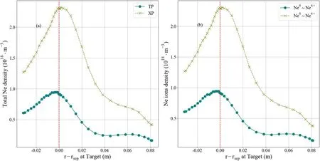
Figure 5.(a)The total neon density and(b)the neon ion densities of the lower charge states at the outer target,with seedings at TP and XP locations respectively.
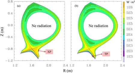
Figure 6.Radiation power density distribution of XP case (a) and TP case (b).
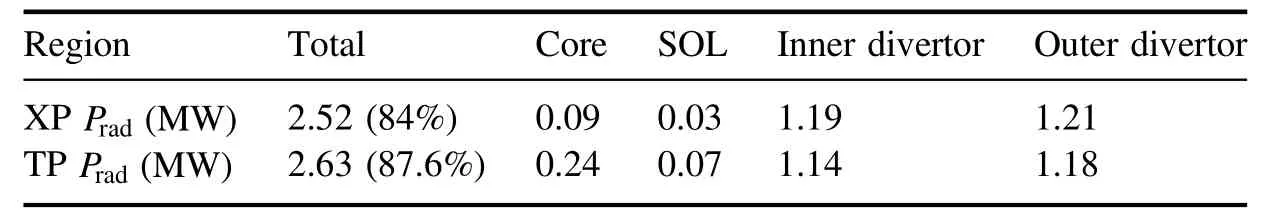
Table 1.The distribution of radiation power in different regions with seeding at two locations.
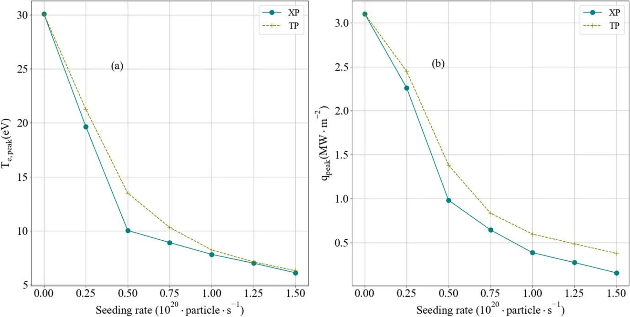
Figure 7.The peak value of (a) electron temperature and (b) heat load at outer target as functions of neon seeding rates.
The difference in the radiation power between the two seeding location cases is shown in figure 6, where the radiation power dominates the target area since the Ne impurity is concentrated in the divertor region.The radiation power of different regions is listed in table 1.The total power radiation loss of the XP case is about 84.6%, and of the TP case is about 87.6%.The power radiation of the TP case is slightly higher than that of the XP case due to the higher impurity density upstream, which clearly causes a higher radiation power in core and SOL region.
To further check the influence of seeding locations on the divertor plasma,we also simulate the seeding rate from1019to 1.5 × 10²⁰s−1.The peak values ofTeandqtotat the outer target as functions of the seeding rate are shown in figure 7.It can be seen clearly that, as the seeding rate increases, the peaks ofTeandqtotdecrease;and the peak heat load in the XP case is lower than that in the TP case slightly.It indicates that the difference between two seeding locations is more significant as the seeding rate begins to increase.However,whenTe,peak≤10 eV,the decrease of the peak electron temperature is getting slower as the seeding rate increases,due to the outer target achieving detachment [18, 23].Also, with the rising seeding rate, the peakTeof the two cases at the outer target becomes insignificant.The reason is that in high seeding conditions,the electron temperature variation gets smaller and smaller as the seeding rate rises, due to a deeper and deeper detachment being achieved at the target.
4.Summary
The importance of the impurity seeding at different locations and its effect on D-SOL plasma processes has been studied for EAST geometry and parameters, numerically by SOLPSITER code.The simulation results show that the neon impurity seeding is very effective to enhance the radiation power loss, and thus to reduce the temperature and heat load on the divertor target.In the same upstream conditions, the seeding locations have significant effects on both divertor plasmas and upstream profiles.In the divertor region, seedings at the TP and the XP positions can both achieve the partial detachment at the inner and the outer targets, withTe<6 eV at the strike point, though still>10 eV in the far-SOL region.The radiation power loss due to the neon impurity seeding is mainly concentrated in the divertor region in both cases.However, seeding at the XP leads to lower temperature and heat load flux than that for TP in both targets,because the neon density of the XP case is much higher than that of the TP case.As the seeding rate increases, the peak heat load flux at outer target for the XP case is lower than that for the TP case, and the peak temperature variation becomes insignificant.In the upstream region, the electron density profile rises due to the neon impurity seeding, and thus the temperature profile drops.The modeling results show that the neon impurity density is mainly located near the inner LCFS,while the neon content in the core region is still noticeably low (cNe,CEI,TP=2.13%,cNe,CEI,XP=1.88%).Moreover, the impurity density of the TP case is higher than that of the XP case.It indicates that, for seeding at the TP, the neon ions move more easily upstream into the core plasmas.In other words, seeding at the private-flux region (the TP location) is not beneficial for the plasma confinement, especially in high seeding rate conditions.
Not only is the D-SOL plasma affected by the impurity seeding location, but also the transport coefficients, and the drift in the impurity transport process also plays an important role.Therefore,the impurity transport with different transport coefficients and the influence of drift should be considered and further investigated in future work.
Acknowledgments
We would like to express our gratitude to Xavier Bonnin of ITER Organization for the help in the application of the SOLPSITER code.This work was supported by the National Key Research and Development Program (No.2018YFE0303105),National MCF Energy R&D Program(No.2019YFE03080300),and National Natural Science Foundation of China (No.11975087).
猜你喜欢
趣味(数学)(2019年9期)2020-01-01
教育·学习(2018年9期)2018-12-04
魅力中国(2018年4期)2018-07-30
现代养生·上半月(2017年5期)2017-05-04
东方教育(2017年1期)2017-04-20
中国果业信息(2017年5期)2017-01-13
恋爱婚姻家庭(2015年24期)2015-12-06
恋爱婚姻家庭·养生版(2015年8期)2015-05-14
Nuclear Science and Techniques(2014年1期)2014-04-24
 Plasma Science and Technology2022年1期
- Plasma Science and Technology的其它文章
- On the stability of small-scale ballooning modes in axisymmetric mirror traps
- Viscous effects on plasmoid formation from nonlinear resistive tearing growth in a Harris sheet
- Microwave preionization and electron cyclotron resonance plasma current startup in the EXL-50 spherical tokamak
- FEQ: a new flux coordinates based equilibrium solver including both magnetic axis and separatrix
- Dispersion and damping rate of Langmuir wave in space plasma with regularized Kappa distributed electrons
- Response of the low-pressure hot-filament discharge plasma to a positively biased auxiliary disk electrode