
Power characteristics of multiple inductively coupled RF discharges inside a metallic chamber
2022-02-15 11:08DaneLOJENRokZAPLOTNIKMiranMOZETIAlenkaVESELandGregorPRIMC
Plasma Science and Technology 2022年1期
Dane LOJEN, Rok ZAPLOTNIK, Miran MOZETIČ, Alenka VESEL and Gregor PRIMC
1 Department of Surface Engineering, Jozef Stefan Institute, Jamova cesta 39, 1000 Ljubljana, Slovenia
2 Jozef Stefan International Postgraduate School, Jamova cesta 39, 1000 Ljubljana, Slovenia
3 Plasmadis Ltd, Teslova ulica 30, 1000 Ljubljana, Slovenia
Abstract The characteristics of an innovative configuration of multiple radiofrequency (RF) coils immersed in a large metallic chamber are presented.Water-cooled copper coils were mounted within the slits of double-walled glass tubes, which were immersed into a stainless-steel chamber.The coils were connected in parallel to a gamma-type matching network, powered by an RF generator operating at industrial frequency.Adjustable leads enabled optimisation of the line impedances and thus uniformly distributed RF power across the four coils.Transitions from E-to H-mode and vice versa were measured for all coils at various oxygen pressures between 5 and 25 Pa.A uniform plasma was sustained in H-mode at the absorbed power threshold, which increased monotonously with increasing pressure in the metallic chamber.All coils exhibit the same E- to H-mode transition hysteresis and need the same amount of power for transitioning from E- to H-mode.The setup enables maintaining uniform plasma in virtually any number of coils at high power without the risk of arcing and without the dead volume typical for a classical configuration with coils mounted outside the metallic chamber.
Keywords:inductively coupled plasma,large-area plasma,E-to H-mode transition, high power
1.I ntroduction
Inductively coupled radio-frequency(RF)plasmas are widely used for tailoring the surface properties of solid samples,such as cleaning, functionalisation, nanostructuring, etching and deposition of various coatings.The key advantage of such plasmas over those sustained by other types of discharges arises from the fact that inductively coupled plasma (ICP) is often only in contact with dielectric materials; thus, the risk for unwanted effects such as the sputtering of electrodes or electrode coating and heterogeneous surface recombination of plasma radicals is suppressed.ICPs in H-mode can be sustained at a relatively high power density(power absorbed by a unit volume) in a limited range of plasma volumes and pressures.Such plasmas cannot be sustained in large volumes at moderate pressures, which are usually needed in industrial applications.The solution to this natural limitation is to apply several coils mounted on a large vacuum chamber; however,sustaining uniform plasma in numerous coils still represents a technological challenge.
Inductively coupled RF discharges have been popular for sustaining gaseous plasma for decades.The discharges are self-sustained in such a configuration up to the atmospheric pressure and beyond of noble gas, providing that the electromagnetic field is large enough [1].Sustaining such discharges in molecular gases at atmospheric pressure is more challenging, but specific solutions enable even such devices to be useful for gas-phase chemistry [2].The majority of applications, however, employ low-pressure devices for sustaining stable and uniform ICPs.Two types of ICPs are most often used: cylindrical- and planar-type [3].A classical cylindrical-type ICP configuration employs a coil wrapped around a cylindrical dielectric tube connected to an RF generator via a matching network [4].Although the theoretical background was elaborated decades ago [5], the theory of such discharges is still a subject of scientific interest [6].
ICP at low pressure can be sustained in two distinctive modes: the E- and H-mode [7].The difference between modes is significant and visible with the naked eye because the H-mode is much more luminous than the E-mode.In E-mode,the primary coupling is capacitive,i.e.the discharge is governed by the capacitive character of the plasma impedance.In H-mode, however, the electrons are coupled with the induced electric field in the volume inside the coil rather than accelerated in the sheath next to the powered segment of the coil.This feature enables the ICP to be sustained at a large power density without the danger of melting the dielectric walls of the plasma reactor due to extensive ion bombardment.An excellent introduction to capacitive and inductive modes was published recently [8].The transition between modes is indistinct at low pressures, below a few 0.1 Pa [9],but becomes abrupt at higher pressures.The plasma luminosity may rise by 3 orders of magnitude upon transition from E- to H-mode at the pressure of several tens of Pa [10–13].Some authors also mention W-mode, characterised by the‘wave heating’ of the electrons, resulting in efficient RF power absorption in the bulk of the plasma[9].The W-mode is found in ICPs with magnetic field presence above a certain threshold value due to the helicon mode.
Initially, the ICP is always ignited in E-mode.The plasma transforms to H-mode under favourable conditions.The transformation occurs at a suitable forward RF power.The discharge impedance drops instantly at the transition,and the absorbed power increases instantly.Further increase of the available power causes the plasma density to increase.In the opposite direction, i.e.upon reducing the discharge power,plasma remains in H-mode(i.e.high plasma density and high luminosity) until a critical power is achieved.As soon as the power is lower than the critical value,the abrupt transition to E-mode occurs.The transition from E- to H-mode always occurs at lower forward power than the transition from the E-to-H-mode.The ICP is either in E-mode (low absorbed power) or H-mode (high absorbed power).In between, there is a so-called inaccessible region of absorbed powers [14].With a fixed chamber geometry and coupling peculiarities,the width of the inaccessible region depends on the type of gas and increases with increasing pressure; it may be several 100 W.Details about the transition from E-to-H-mode in molecular gases at higher pressures have been published recently [15].Discharge instabilities have been reported for ICPs sustained at a relatively low power densities in electronegative gases [16].
While the classical configuration with a coil wrapped around a dielectric tube is acceptable for treating various samples in small experimental plasma reactors, upscaling of the ICP sustained in H-mode to large systems is not trivial.One solution is the application of numerous coils mounted outside a large metallic chamber.Chang’s group published an excellent paper revealing 16 coils on a single metallic chamber [17, 18].The key technological challenge was the adjustment of line impedances.A direct connection from the coil’s ground to the shield of the coaxial transmission line was vital to obtain H-mode plasmas within all coils.Namely,only equal ground paths for each coil enabled a relatively uniform distribution of available RF power to the plasmas in all coils.The authors[18]proved the principle for argon at a rather low pressure of 1.3 Pa.The operation of such devices with molecular gases at elevated pressures remains a technological challenge,despite recent achievements.For example, another group [19] reported a relatively uniform nitrogen plasma in a system almost identical to [18].
An alternative to a multi-coil system is to apply a spiral instead of a coil [20].In such a case, the metallic flange is substituted with a dielectric one, and a spiral is mounted on the flange.Theoretical simulations show that the inductive component might be larger than the capacitive at RF power as low as 5 W [21].The transitions between E- and H-mode in such systems were studied in detail for plasmas sustained in argon,nitrogen,oxygen and mixtures of these gases[22,23].Interestingly, they found a minimum power of solely 20 W for E-to H-mode transition in argon with a pressure of about 3 Pa.In mixtures of oxygen and nitrogen at the same pressure,transition occurred at about 5 times greater power.At a moderate pressure of 13 Pa, the transition occurred at about 200 W for molecular gases.Interestingly enough, theoretical predictions forecast the highest electron density in the middle of the plasma reactor,instead of at the spiral’s proximity[24].
Another alternative is the application of low-impedance antennas.In this case, numerous loops are mounted inside a metallic chamber and coupled in parallel to an RF generator.One of the first reports was provided by Kim and Yeon [25].They sustained plasma in argon at 2 Pa using an RF power of up to 5 kW.No apparent transition between the discharge modes was reported in this configuration.Simultaneously,Setsuhara et al [26] reported a similar device operating in argon at 1.5 Pa and found gradients in plasma parameters when a single RF generator was used to power multiple loops coupled in parallel.A more complex configuration of lowimpedance antennas was published recently [27].
The preferred gas in the literature survey above is argon and the preferred pressure range is between 1 and 10 Pa.Multiple coils, however, may also be installed inside the chamber and operate at pressures as high as 300 Pa, as reported by Liang et al[28].The arcing,which should appear at this pressure under ordinary conditions, was avoided by placing each coil in a tube kept at atmospheric pressure because the tubes were open to the outer environment through the hollow sustaining pole.With this innovative design, the authors[28]managed to sustain dense uniform plasma within the coils in a range of pressures between 10 and 300 Pa.The electron temperature was close to 1.5 eV and the density exceeded 1019m−3at elevated pressures.However, these coils had a central magnetic core and were only used as an antenna, forming plasma outside the coil.
In the present paper, we present the innovative configuration of multiple RF coils immersed in a large metallic chamber in such a way that ICP is excited inside the coil where the magnetic field is largest.With this configuration,one can ignite an H-mode ICP over a large area inside the metallic chamber at pressures up to few tens of Pa.The transitions from E- to H-mode were investigated in oxygen plasma generated in the experimental system with 4 such coils.
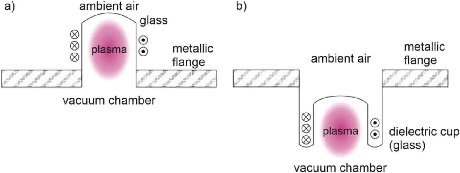
Figure 1.(a) A classical and (b) our positioning of the RF coil.
2.Experimental details
The classical configuration and our positioning of RF coils inside a metallic chamber are shown in figure 1.In the classical configuration adopted by numerous authors [3, 14–17,26], the RF coil is positioned outside the metallic flange(figure 1(a)),so the dense plasma in H-mode is limited to the space outside of the chamber.Therefore,this plasma is not in contact with samples placed inside the chamber.In the configuration proposed in this paper, the dense plasma also stretches into the main chamber (figure 1(b)).
More details of our positioning of the coil within a slit of a double-walled glass tube, i.e.dielectric cup are shown in figure 2.The dielectric cup was made of borosilicate glass.The outer and inner diameters of the slit between the cup’s walls were 55 and 40 mm, respectively.The thickness of the outer wall of the cup was 4 mm, and of the inner wall was 2.5 mm.The coil was made of a copper tube with outer and inner diameters of 3 and 1 mm,respectively.It was connected to a cooling water system maintained at a pressure of 5 bar.Although placed inside the metallic chamber, the coil was in ambient air due to the special construction peculiarities of the dielectric cup.A Teflon spacer was placed between the powered and grounded segments of the copper tube,as shown in figure 2.Such conditions prevented arcing between the coil’s powered and grounded sides even at the highest discharge powers.
The coils of our configuration were mounted onto a metallic flange of the vacuum chamber with a height of 0.5 m and a diameter of 0.6 m.All connections between the matching network,the coils and the ground were adjustable in length to enable fine adjustment according to suggestions published in[17,18].Four coils were connected in parallel to the matching network,which was in turn connected to an RF generator.The matching network was gamma-type, i.e.consisting of two variable capacitors (Commet Maxi-Con), each with a capacitance between 20 and 250 pF.The RF generator was an Advanced Energy Cesar 1350, with an adjustable forward power of up to 5 kW at the maximum voltage of 795 V.A photograph of the outer side of the anodised aluminium flange with all four cups and electrical leads is shown in figure 3.
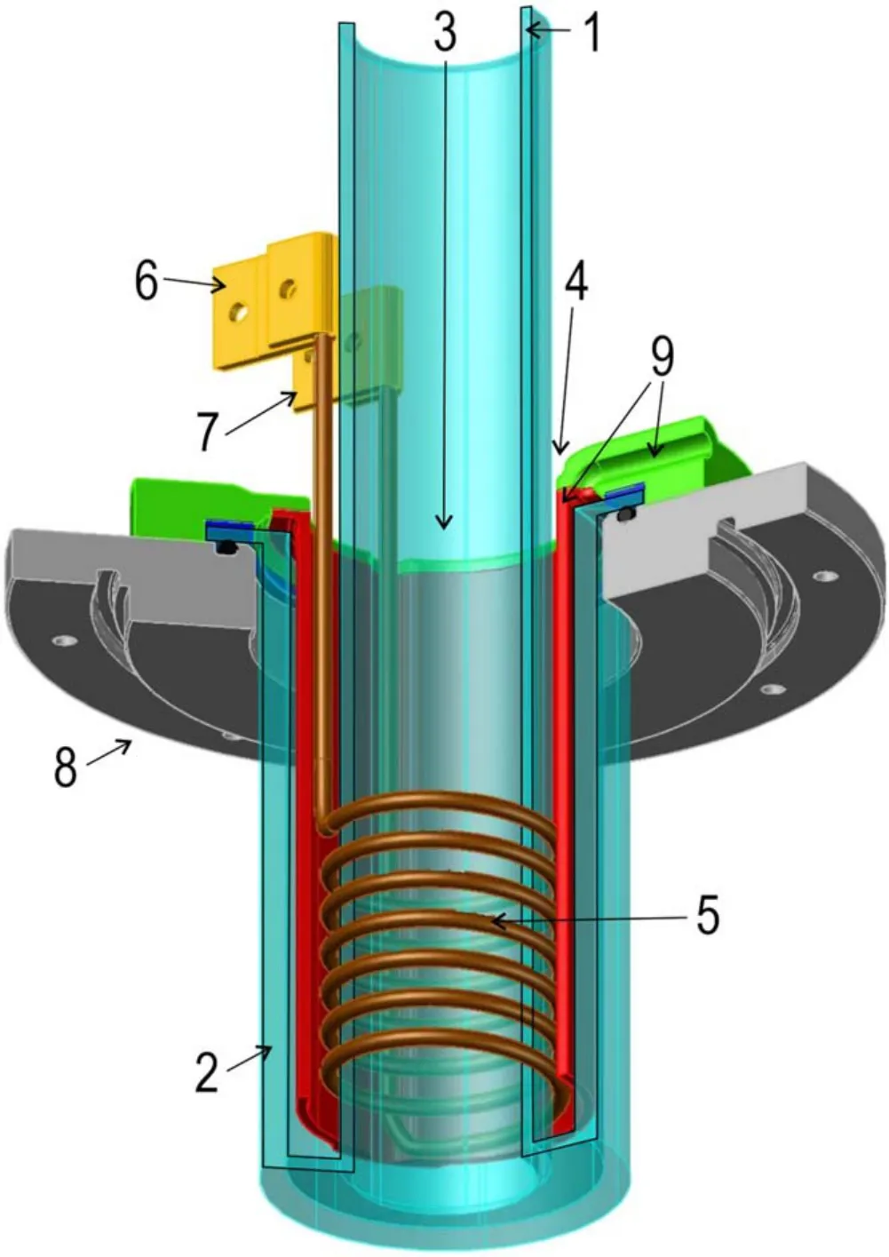
Figure 2.A dielectric cup with the RF coil.1—inner wall, 2—outer wall, 3—vacuum side, 4—atmospheric pressure side, 5—coil, 6—connection to the power supply, 7—ground, 8—fixation ring, 9—forced air cooling air lead and upper glass fixation ring.
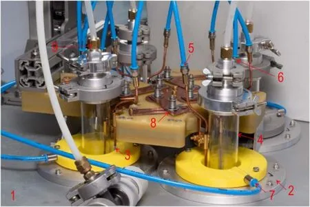
Figure 3.A photo of the 4 coils mounted on the flange.1—anodised aluminium flange, 2—fixation flange, 3—Teflon spacer, 4—inner wall, 5—water inlet, 6—water outlet, 7—compressed air inlet, 8 –hot-wire length regulation slider, 9—gas inlet.

Figure 4.Plasma in the reactor with an oxygen pressure of 20 Pa and total forward power of 1500 W.
The chamber was pumped with a two-stage rotary pump with a nominal pumping speed of 40 m3h−1,and an ultimate pressure below 0.1 Pa.Oxygen gas of commercial purity was leaked into the metallic chamber during continuous pumping.The pressure in the chamber was measured with an absolute capacitive gauge (MKS pressure transducer 722B) and was adjusted between 5 and 25 Pa.Plasma was ignited at low forward power (i.e.in E-mode).The forward power was increased gradually to detect the transition from E- to H-mode.A photograph of the inner side of the chamber with four plasmas in H-mode is shown in figure 4.
3.Results and discussion
As already mentioned,the transition between E-and H-mode is clearly visible with the naked eye because H-mode is much more luminous than E-mode.The emission intensity of H-mode plasma is more than two orders of magnitude larger than the emission intensity of E-mode plasma.This can be measured by optical emission spectroscopy(OES).In figure 5 optical emission spectra of E- and H-mode plasma are presented.It can be seen that the intensities of oxygen lines in H-mode plasma (figure 5(b)) are more than 200 times higher than the intensities of oxygen lines in E-mode plasma(figure 5(a)).
The transitions between E- and H-mode were measured systematically at different oxygen pressures.First, a pressure was fixed to a selected value, and the RF generator was switched on at low forward power.The forward power was increased, and both forward, as well as reflected power were monitored.The transition from E-to H-mode was observed as a sudden increase of plasma luminosity.The forward power was increased up to approximately 3000 W.The plasma was sustained at this power for a few minutes, and then the forward power was gradually decreased.The transitions from Hto E-mode were measured at different pressures when decreasing the forward power from maximum to minimum power value.
Figure 6 represents the forward powers at which transitions from E- to H-mode were observed versus the pressure for all four coils.The transitions occur at the relatively low forward power of approximately 400 W at the lowest pressure of 5 Pa.The transition shifts to higher powers at higher pressures.In the first approximation, the forward power required for transitions from E- to H-mode increases quite linearly with increasing pressure.At the maximum experimental pressure, i.e.25 Pa, the required forward power was approximately 1700 W.The transition never occurred in all coils simultaneously.With increasing power, E- to H-mode transitions occurred in coils one by one.The sequence of the coils for these transitions is not always the same,nevertheless,the differences between coils are not dramatic, as revealed in figure 6.Such deviations between coils are a consequence of the peculiarities of plasma impedances.Despite all precautions taken when constructing the electrical circuit, minor impedance differences cause sequential transitions.Incidentally,the lowest power needed for the transition from E-to-Hmode at 5 Pa was observed for coil#1,followed by#2,#3 and #4.At 10, 15 and 25 Pa, coil #3 required the highest forward power for the transition indicating minute details that govern the E-H transitions.
The curves in figure 6 are not perfectly linear because of the peculiarities described above.However, if points in figure 6 are connected not by the E- to H-mode transition of the particular individual coils but by the number of coils that underwent transition,the curves become totally linear.In this case,it is not important in which coil sequence the transitions occurred.This is presented in figure 7, where also linear fits are plotted.From here on all the curves will be plotted in the same manner, with number of coils connected.Now, the linearity is more obvious.The RF generator power needed for a certain number of coils to be ignited in H-mode at a certain pressure can simply be calculated using linear fits.
The RF generator was also equipped with a reflected power meter.The real power dissipated on the coils is the difference between the forward and reflected power.The real power needed for the transition of plasma from E-to-H-mode versus pressure is shown in figure 8.Results for the transitions of all four coils are not much different from the results in figure 7 because of the almost optimal coupling.Specifically,the matching network has been optimised in the state where all four coils were in H-mode,i.e.reflected power was almost zero for all four coils at the transition from E- to H-mode.This optimisation was performed before measurements at every oxygen pressure.However,because of the optimization method of the matching network, the curves, for the case where one or more coils are in E-mode, are lower than the curves in figure 7.
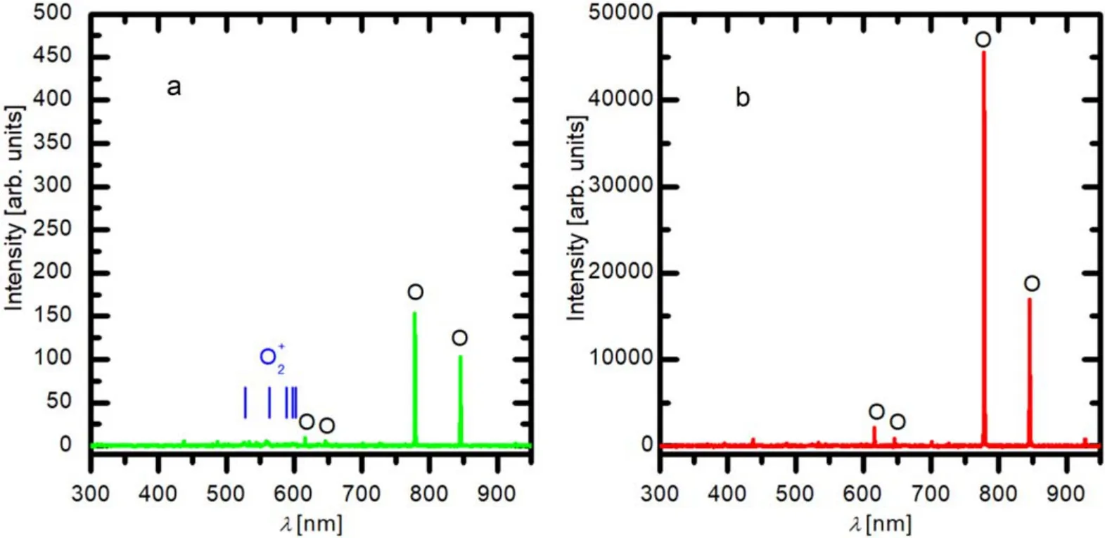
Figure 5.OES spectra of E-mode plasma (a) and H-mode plasma (b).

Figure 6.Forward powers at transitions from the E- to H-mode for different coils versus pressure.
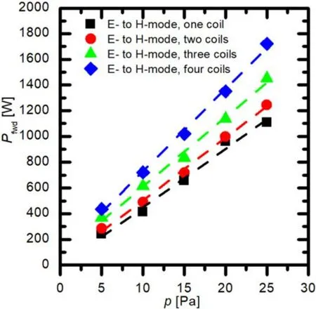
Figure 7.Forward powers at transitions from E- to H-mode for different numbers of coils versus pressure.
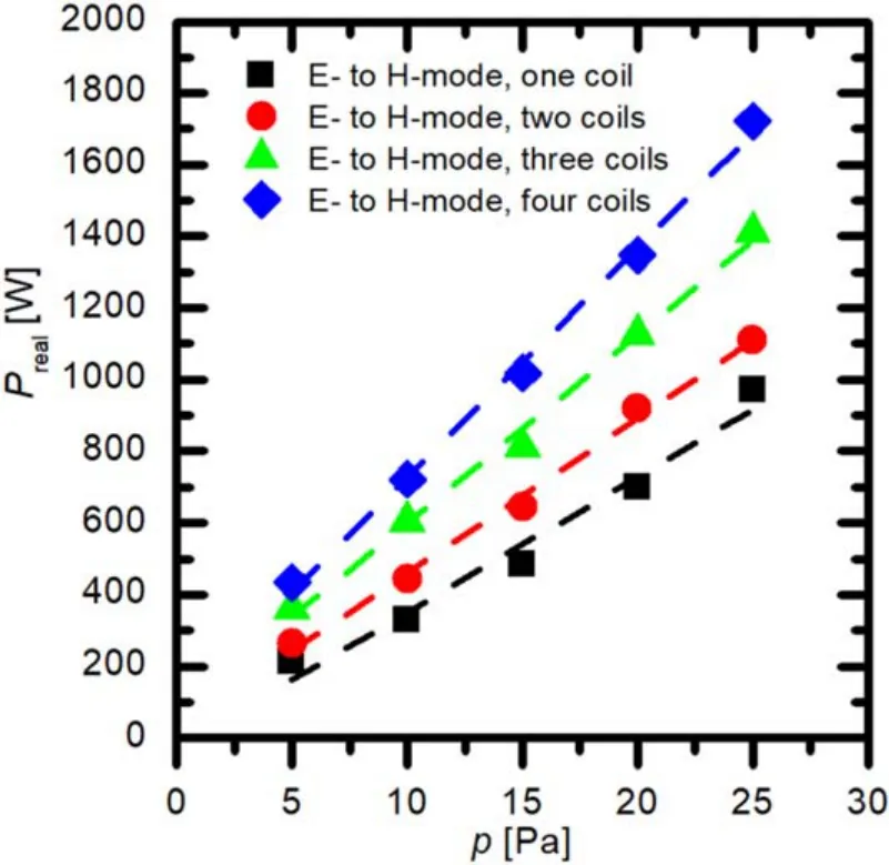
Figure 8.Difference between forward and reflected powers (real power) at transitions from E- to H-mode versus pressure.
The transitions between the discharge modes exhibit hysteresis, i.e.the transition from E- to the H-mode always appears at a larger power than the transition from H- to E-mode [29].The hysteresis is the consequence of the fact that H-mode will persist at moderate power if the plasma density is large enough to assure absorption of energy from the electric field by plasma electrons.The transition from Hto E-mode will occur once the electron density drops below the critical value.The transitions were measured at different pressures,and the results are summarised in figure 9.The first observation is that lower forward powers are needed for H-to E-mode transitions(figure 9)than when measuring the E-to-H transitions (figure 7).For example, at 25 Pa, where the differences are most striking,the H-to E-mode transition for the first coil occurs at a forward power of 1200 W,while the last transition from E-to H-mode is observed at power as large as 1722 W.The H- to E-mode transition for the last coil occurs at a forward power of 830 W,while the first transition from Eto H-mode is observed at 1108 W.
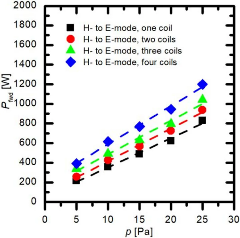
Figure 9.Forward powers at transitions from H- to E-mode for different coils versus pressure.
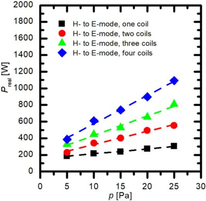
Figure 10.Difference between forward and reflected powers (real power) at transitions from H- to E-mode versus pressure.
The real (forward minus reflected) powers where transitions from the H- to E-modes occur are plotted in figure 10.The values at 25 Pa are similar as in figure 9 for the first coil,where the H-mode is lost (approximately 1100 W) but much different for the last coil (approximately 300 W).The large difference is a consequence of the matching network optimisation method described above.That is why a small amount of power is absorbed in coils when they are in E-mode.As long as all coils are in H-mode,the real power is fairly equally distributed among all four coils.Once one coil transitions to E-mode, the available power is shared among the three coils which still persist in H-mode.As revealed from figure 10,the differences between the real powers absorbed in separate coils are nearly equal.For example, at 25 Pa, the critical powers needed to sustain the plasma in H-mode are 304,554,807 and 1093 W for one, two, three and all four coils in H-mode,respectively.Such a linear increase of the real power with the increasing number of coils in H-mode reflects that the absorbed power is marginal in E-mode compared to H-mode.This means that each additional coil needs the same amount of real power in order to sustain H-mode.
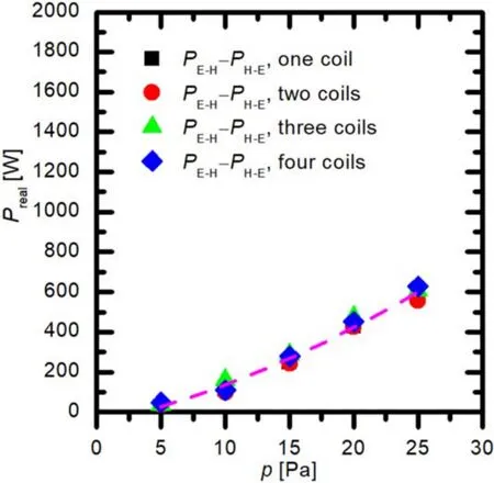
Figure 11.The width of hysteresis versus pressure.
In figures 9 and 10, a linear increase of power versus pressure can be seen.A few authors reported the pressure dependence of the critical power needed to sustain plasma in H-mode [27, 28], but most are limited to experiments at low pressure (preferably argon) plasma, where plasma can be sustained in H-mode at reasonably low power.Due to the technological applications, however, higher pressures are preferred because the density of electrons [27, 28], the radiation in the VUV range [30], and the density of neutral radicals[8]are larger than those at very low pressures.At the lowest pressure used in this study, i.e.5 Pa, all of four coils were sustained in the H-mode at the absorbed power of only 386 W(figure 10).Furthermore,the same applies also for the forward power (figure 9) because the discharge coupling for all of four coils in H-mode at low powers and low pressure is near the optimum value of the matching, which was set as described above.However, with increasing pressure, the real power needed to sustain all four coils in H-mode increases and reaches 1093 W at 25 Pa.For the ignition of H-mode from E-mode of course even more power is needed,i.e.in the case of 25 Pa more than 1700 W.Sustaining H-mode and especially igniting the H-mode in several coils at larger pressures, therefore, requires a rather powerful RF generator.
As mentioned earlier, there is a hysteresis behaviour between the transition from E- to H-mode and back H- to E-mode in ICPs.Because we have here four ICPs there are four hystereses stacked one after another.The width of these hystereses,i.e.the difference between the real power of the Eto H-mode transition (figure 8) and the H- to E-mode transition(figure 10)versus pressure,is shown in figure 11.It can be clearly seen that the width of hysteresis at a certain pressure is almost the same for one, two, three or all four coils.This means that each additional coil will behave the same.
In figure 11 it can also be seen that the hysteresis energy width increases with pressure.The marginal energy width of solely 35 W is observed at the lowest pressure of 5 Pa.As mentioned earlier, the width becomes immeasurable at very low pressures[8].Figure 11 reveals a dramatic increase of the hysteresis width with increasing oxygen pressure.At the highest pressure used in these experiments(25 Pa),the energy width was greater than 600 W.Therefore, one can save a lot of energy if plasma is ignited at the power needed for the Eto H-mode transition and then the power is lowered near the power of the H-to E-mode transition,while maintaining all of the coils in H-mode.
4.Conclusions
An innovative discharge system consisting of four ICPs coupled inside a metallic chamber was constructed and transitions from E- to H-modes and vice versa were measured at different oxygen pressures.Oxygen is a molecular gas of numerous excitation levels, so the electron energy is predominantly lost for molecule dissociation and excitation of various molecular and atomic states.Consequently, the discharge power needed to sustain ICP in oxygen gas in H-mode is much larger than in noble gases.We have shown that careful alignment of the electrical leads enables sustaining H-mode in all of four coils coupled in parallel to the RF power source.The transitions from E- to H-mode exhibited hysteresis.The width of hysteresis increased with increasing pressure.At the highest oxygen pressure in these experiments(25 Pa), the minimum discharge power still enabling operation in H-mode was approximately 300 W per coil.This is about the same power as observed for a simple one-coil discharge [8, 13].The results presented in this paper clearly show that oxygen plasma can be sustained in H-mode at an optimal discharge power, even for multiple coils mounted inside a large metallic chamber.Possible applications include both etching and plasma-assisted deposition of various coatings where a rather large power density at a minimum interaction between positive ions and the walls of the discharge chambers is preferred.
Acknowledgments
This research was funded by the Slovenian Research Agency,project No.L2-9235 (Innovative configuration of inductively coupled gaseous plasma sources for up-scaling to industrialsize reactors) and core funding P2-0082 (thin-film structures and plasma surface engineering).
 Plasma Science and Technology2022年1期
- Plasma Science and Technology的其它文章
- Numerical studies of the influence of seeding locations on D-SOL plasmas in EAST
- On the stability of small-scale ballooning modes in axisymmetric mirror traps
- Viscous effects on plasmoid formation from nonlinear resistive tearing growth in a Harris sheet
- Microwave preionization and electron cyclotron resonance plasma current startup in the EXL-50 spherical tokamak
- FEQ: a new flux coordinates based equilibrium solver including both magnetic axis and separatrix
- Dispersion and damping rate of Langmuir wave in space plasma with regularized Kappa distributed electrons