
Anisotropic and valley-resolved beamsplitter based on a tilted Dirac system
2022-08-02 03:01XixuanZhouJianlongZheng郑建龙andFengZhai
Xixuan Zhou, Jianlong Zheng (郑建龙)and Feng Zhai
Abstract We investigate theoretically valley-resolved lateral shift of electrons traversing an n–p–n junction bulit on a typical tilted Dirac system (8-Pmmn borophene).A gauge-invariant formula on Goos–Hänchen (GH) shift of transmitted beams is derived, which holds for any anisotropic isoenergy surface.The tilt term brings valley dependence of relative position between the isoenergy surface in n region and that in the p region.Consequently,valley double refraction can occur at the n–p interface.The exiting positions of two valley-polarized beams depend on the incident angle and energy of incident beam and barrier parameters.Their spatial distance D can be enhanced to be ten to a hundred times larger than the barrier width.Due to tilting-induced high anisotropy of the isoenergy surface, D depends strongly on the barrier orientation.It is always zero when the junction is along the tilt direction of Dirac cones.Thus GH effect of transmitted beams in tilted Dirac systems can be utilized to design anisotropic and valleyresolved beam-splitter.
Keywords: Goos–Hänchen shift, anisotropic isoenergy surface, 8-Pmmn borophene, valley double refraction
1.Introduction
The common wave nature of light and electrons makes it possible to manipulate electrons by means of components inspired by geometrical optics [1–19].For ballistic electrons traversing a boundary separating two uniform regions with different potentials, reflection and refraction happen in analogy to a light beam incident on an interface between materials with different optical indices.Both positive and negative refraction have been observed [14] experimentally in graphene junctions.It is well known that a totally reflected beam of light undergoes a lateral displacement relative to the incident point.This phenomenon is referred to as Goos–Hänchen(GH)shift[20]and has been generalized to partial reflections and also transmitted beams[3].The GH effect in graphene p–n–p junctions has been predicted to result in an 8e2/h conductance plateau [8].The GH shifts of transmitted electron beams have been utilized to design a spin beam splitter [6]based on a two-dimensional(2D)electron gas or valley beam splitter [11] based on strained graphene.There are extensive studies on the GH shift of electrons in materials with an isotropic Fermi surface, especially in Dirac materials with linear dispersion.Very recently,Ghadiri and Saffarzadeh[19]have calculated the GH shift of transmitted electrons on the surface of a topological insulator with a potential barrier and a warped Fermi surface.Their derivation on the GH shift is made only for a special barrier orientation which is straightforward but cumbersome.A general formula and numerical approach are necessary for the GH shift of electrons on an anisotropic Fermi surface.
Materials with a gapless dispersion and anisotropic Fermi surface are similar to anisotropic optical medium.Among these materials tilted Dirac systems have attracted great research interest.Tilted Dirac cones can appear in 8-Pmmn borophene[21, 22], organic conductor α -(BEDT-TTF)2I3[23, 24], quinoid-type or partially hydrogenated graphene [25, 26], and 1T′monolayer transition metal dichalcogenides [27, 28].Among them, the organic 2D conductor α-(BEDT-TTF)2I3has been experimentally verified to host a pair of tilted and anisotropic Dirac cones.Some unusual electronic and transport properties caused by the tilt of the Dirac cone have been demonstrated theoretically, such as strongly anisotropic plasmon [29] and optical conductivities[30],unique intervalley damping effect in magnetoplasmons[31],valley-dependent Weiss oscillation[32],nearly perfect valley polarization induced by a single ferromagnetic gate [33], and light-driven metal–insulator transition[34,35].Electron optics based on tilted Dirac systems has been discussed in several works [33, 36, 37] which concern valleydependent electron retroreflection, oblique Klein tunneling,generalized Klein tunneling, and Veselago focusing.The GH shift in tilted Dirac systems has not been studied so far.In this work,we take 8-Pmmn borophene as an example to investigate the GH shift of electrons on an anisotropic Fermi surface.
2.Model and formalism
The 2D electron system in 8-Pmmn borophene under consideration is depicted in figure 1, which is modulated by an electric potential U(r) (yellow-shadowed region) due to a metallic gate on top.The electric potential in the borophene plane(XOY)varies only along the x axis and vanishes outside the region 0 <x <W.The X axis is perpendicular to the σvmirror in pristine 8-Pmmn borophene.The angle between these two directions is denoted as α (0 ≤α ≤π/2).The motion of an electron in a given valley τ can be described by the low-energy effective Hamiltonian [22, 32, 37]

Figure 1.Schematic of the considered device.The electric potential varies only along the x axis and vanishes outside the shadowed region.The x axis has angle α to a symmetry axis X of pristine 8-Pmmn borophene.
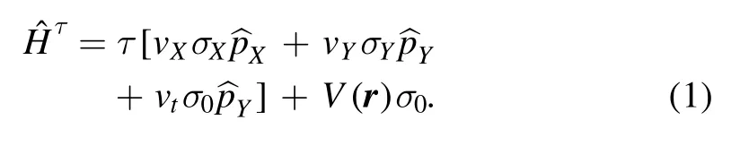
Here τ=±1 stands for the kDand-kDvalleys, σX, σYtogether with σZare three Pauli matrices, σ0is a unit matrix,and= -iħ∇is the momentum operator.Hereafter the velocity, length and energy are, respectively, in units of vF=106m s-1, L0=50 nm and E0=ħvF/L0=13.2 meV.Without specification,the three velocity parameters vX,vYand vtin units of vFare taken,respectively,as[22]0.86,0.69,and 0.32.For some 2D organic conductors [23, 24] or graphenetype materials [25, 26] with two degenerate and tilted Dirac cones,the low-lying excitations near Dirac points can be also described by the Hamiltonian equation (1).
2.1.Scattering states

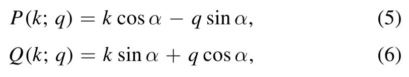
Here Cj1and Cj2are underdetermined coefficients, the function P=P(k;q) and Q=Q(k;q) are defined as
and the wave vectors kj1and kj2are two solutions of the quadratic equation (with unkown k)


2.2.GH shift of outgoing beams
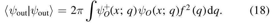
Consider a wavepacket consisting of incident electrons in valley τ with the same energy E but different transverse wave vector q

For the numerator

the integral over y is given by
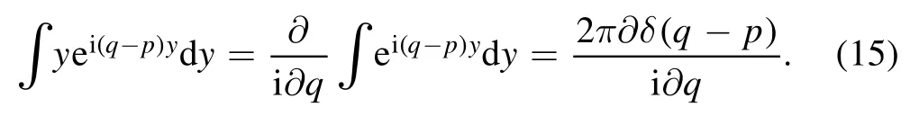
Using the identity

we get

Here we have removed the term

which is purely imaginary.A similar calculation leads to

The GH shift is defined as the difference in the transverse position between the outgoing beam (at the interface with abscissa x >W)and the incident beam(at the interface x=0)


3.Results and discussions
For simplicity, we consider the electric potential with a rectangular shape [see figure 2(a)], i.e.U(x)=UΘ(x)Θ(W-x)with Θ(x) the Heaviside step function and U >0 the barrier height.For an energy E >0 and barrier orientation α=15°,the isoenergy line in the lead region for electrons in valley τ is plotted in figure 2(b),which is an ellipse centered at the point with pX=0 andHere pXand pYare(dimensionless) momentum components along the X and Y axis depicted in figure 1.The ellipse equation is given by equation (7) and denoted as fτ(k, q;E)=0.Note that f-1(k,q;E)=f1(-k, -q;E).The major and minor axis of the ellipse is along the pYand pXaxis and have lengthandOne can see from equation (9) that the incident direction is perpendicular to the tangent of the isoenergy line in the (k, q) plane.As an example,in figure 2(b)we show a positive incident angle φc2for electrons in valley τ=-1.Note that electrons in two valleys with the same incident angle φ have different transverse wave vectors q±.The isoenergy surfaces in the barrier region are given by fτ(k, q;E-U)=0, which are similar to those in the lead region with a scaling factor|E-U|/E.In the case E <U, the ellipse f-1(k, q;E-U)=0 is below the ellipse f1(k, q;E-U)=0, as shown in figure 2(b).In the (k,q) plane a horizontal (dashed) line q=q0represents the conserved transverse wave vector.When it intersects with both the ellipse fτ(k, q;E)=0 and fτ(k, q;E-U)=0,refraction occurs at interface x=0 for an incident electron in valley τ.The sector of allowed q0depends on the topmost and bottommost points of the two ellipses.For 0 <2E <U the critical values qc1and qc2together with the critical angle φc2are depicted in figure 2(b) for valley τ=-1.In this case, a valley-unpolarized beam with incident angle φ ∈(-φc2,φc2)will split in the barrier region.The two refracted beams with valley index τ=±1 propagate at different angles φ±, as depicted in figure 2(c).The refracted angles can be determined from the ellipse fτ(k, q, E-U)=0.The existing position of refracted beam τ at the interface x=W is given by the GH shift sτ=sGH(qτ;x=W), which usually differs from=Wtanφτpredicted by the geometric ray.
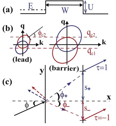
Figure 2.(a) Rectangular potential barrier with height U and width W.(b) Isoenergy lines (for an energy E >0) of electrons in valley τ=1 (blue lines) and τ=-1 (red lines) in the lead and in the barrier.(c) Representation of valley-dependent refraction angle φ±and GH shift s±.

For the barrier orientation α=0, such a lengthy expression can be simplified as

In figure 3 we plot the valley-resolved transmission probability Tτ=|tτ|2and GH shift sτat the interface x=W as functions of the barrier width W under a fixed incident angle φ and energy E.The barrier height and orientation are fixed at U=4 and α=0.Four typical cases are considered and discussed as follows.
The case of normal incidence(φ=0)is presented for E=1(an n–p–n junction) in figure 3(a), where positive/negative refraction (see blue lines) happens in the barrier region for electrons in valley τ=+1/-1.Obviously, this observation violates Snell’s law.The reason is that the anisotropy of the isoenergy line results in an orientation deviation between the momentum and group velocity.For α=0, the isoenergy lines for the two valleys are symmetric about the horizontal k axis.Therefore,the transverse wave vectors q±and refraction angles φ±satisfy q-=-q+and φ-=-φ+.One can also observe that the transmission probability for two valleys coincides.Actually,due to the fact that the inversion operator transforms the Hamiltonianintothe transmission coeffciient satisfies a general relation

Since q-=-q+, this relation leads to T-1=T+1and s-1=-s+1, as seen in figure 3(a).The oscillation of transmission probability with the width W arises from the Fabry–Perot interference.The GH shift sτoscillates around the classical valuewith a small amplitude.
In figure 3(b), the incident angle and energy are chosen as φ=60°and E=1 so that φ is close to the critical angle φc2depicted in figure 2(b) (but for α=0).The two refraction angles are φ+=13°and φ+=-60°.In the barrier region,the longitudinal wave vector for valley τ=+1 is much larger than that for valley τ=-1.Consequently, the Fabry–Perot oscillation for valley τ=-1 has a longer period and larger peak-to-trough ratio than that for valley τ=+1.The wave effect on GH shift is weak for valley τ=+1 but drastic for valley τ=-1.At the first(second)resonant peaks of T-1,the amplitude of GH shift s-1exceeds 48(96),which is 20 times larger than the corresponding barrier width.As demonstrated in[11],the GH shift at a resonant peak increases quickly with the peak-to-trough ratio.When the energy E turns from 1 to 1.1, the critical angle φc2is much close to φ=60° so that|s-1|can exceed 800 >100W.Near these resonant peaks,the valley spatial separation D=|s+1-s-1| is much larger than the counterpart

Figure 3.Transmission T±1 (in black) and GH shift s±1 (in red) at the existing position as functions of barrier width W for electrons in valley τ=1 (solid lines) and τ=-1 (dashed lines).The blue lines representcorresponding refracted beam exists.The barrier height and orientation are U=4 and α=0.The incident energy E and incident angle are (a) E=1, φ=0;(b) E=1, φ=60°;(c)E=1.2, φ=60°;and (d) E = -1, φ=60°.
Once the critical angle φc2is smaller than the incident angle φ,the refracted beam for valley τ=-1 vanishes.Such a case is presented in figure 3(c) with φ=60° and E=1.2.One can see that the transmission T-1and GH shift s-1decays quickly with the barrier width.The corresponding transmitted beam is difficult to detect.The refracted beam for valley τ=-1 remains.In comparison with the case of normal incidence, the oscillation ofwith the width W i s more remarkable due to the larger peak-to-trough ratio in the transmission T+1.Accordingly, the polarity of s+1alternates with W.One can see offsets between peaks of T+1and s+1,which are absent in strained graphene [11].
In the case E <0 <U (a p–p′–p junction), the isoenergy line fτ(k,q;E)=0 is enclosed in the ellipse fτ(k,q;E-U)=0 so that the valley double refraction happens for all incident angles.For E=-1 , the refracted beams for φ=60° are shown as blue lines in figure 3(d), whose orientation angles 25.4° and-7.66° are close to their limits (26.3° and-7.03°)under φ—90°.Now bothandoscillate rapidly with W.The two oscillations have close periods and amplitudes.The valley separation D can vary from 0 to a value higher than 2Dcl.
Hereafter we consider only the n–p–n junction with barrier width W=3 and barrier height U=4.We plot in figures 4 and 5 the variation of transmission T±1and GH shift s±1with the incident angle φ.For the barrier orientation α=0, the transmission (GH shift) for electrons in valley τ=+1 and that for electrons in valley τ=-1 are symmetric(antisymmetric) about the incident angle φ=0, as shown in figure 4.This feature results from equation (29).It is absent for other barrier orientations (see figure 5 for α=45°).For a given valley, in all cases the angular distribution of transmission (GH shift) is not symmetric (antisymmetric) about φ=0.There are several angles where the transmission Tτis perfect.For a resonant peak of Tτ,when its left/right(nearest)transmission minimum is lower than the right/left one, the corresponding maximum of |sτ| locates on its left/right side.The highest|sτ|depends on the incident energy E and barrier orientation α.For E ≤U/2 (such as E=1), the transmission T-τis remarkable near the angle with the largest|sτ|,enabling beam splitting with a large valley spatial separation.In contrast, For E >U/2 (such as E=3), the angular sector with large transmission T-τdoes not overlap with that with large Tτ(or |sτ|), allowing valley filtering of incident beams.For E=U/2 and α=0, both T-1and T+1reach 1 at φ=0.The valley spatial separation in this case is almost twice the largest|s±1|.For E=1 (E=2 and E=3), the largest |sτ| for all incident angles under α=45° is near half (twice) of that under α=0.One can understand these features from the isoenergy surfaces as the way in figure 2(b).

Figure 4.Transmission T±1 (in black) and GH shift s±1 (in red) as functions of incident angle φ for electrons in valley τ=1 (solid lines) and τ=-1 (dashed lines).The barrier height and width are U=4 and W=3.We take α=0 and set E=1 (a), 2(b), and 3(c).

Figure 5.Same as figure 4, but for the barrier orientation α=45°.
Since isoenergy lines depcited in figure 2(b) are high anisotropic,one can expect that the valley spatial separation D depends strongly on the barrier orientation α.In figure 6 we plot the transmission and GH shift as functions of α for a fixed energy E=1.For the transport along the tilted direction of the Dirac cone (α=90°), the product of σzand conjugation K transforms the Hamiltonian H+1into H-1, which leads to t-1(E,q)=t+1(E,q).As a result,the transmission and GH shift are valley-independent at α=90°.In the case of normal incidence (figure 6(a)), as α increases from 0° to 90°, the transmission T±1>0.6 is noticeable.The valley separation D moves up firstly to its global maximum ≈5(at α ≈29.8°)and then decreases oscillatingly to zero.At the fixed incident angle φ=60° (figure 6(b)), there are several values of α where T-1approaches 1 and T+1is remarkable.The valley separation D has a maximum ≈39 at α ≈32.3° near the first peak of T-1.

Figure 6.Transmission T±1 (in black) and GH shift s±1 (in red) as functions of barrier orientation α for electrons in valley τ=1(solid lines) and τ=-1 (dashed lines).The barrier height and width are U=4 and W=3.We take E=1 and set φ at 0 in(a)and 60°in(b).

Figure 7.Transmission T±1 (in black) and GH shift s±1 (in red) as functions of tilt velocity vt for electrons in valley τ=1 (solid lines)and τ=-1(dashed lines).The barrier height,width,and orientation are U=4,W=3,and α=0.We take E=1 and set φ at 0 in(a)and 60° in (b).
The tilt term in equation (1) is essential for the valley spatial separation of transmitted beams.In figure 7 we plot the transmission and GH shift as functions of tilt velocity vtfor the barrier orientation α=0 and a fixed energy E=1.In the case vt=0, one has T+1=T-1and s+1=s-1for all incidences.At normal incidence (figure 7(a)), when vtincreases from 0 to 0.35 the transmission T±1varies slightly while the valley separation D increases gradually from 0 to 4.9.The valley separation D exceeds 77 (16) at large vt≈0.51 (0.46).As for the incident angle φ=60° (figure 7(b)), the transmission T-1has two sharp peaks located at vt≈0.27 and 0.34 where the valley separation D is larger than 27 and 150.
4.Conclusions
In summary,we have derived a general expression for the GH shift of transmitted beams.The formula is independent of the phase choice of incident states and applies for any anisotropic isoenergy surface.We take 8-Pmmn borophene as an example to demonstrate valley beam-splitter based on tilted Dirac systems.The tilt term leads to valley-dependent isoenergy surfaces.Valley double refraction can happen at the n–p interface because the relative position between isoenergy surfaces in the lead and in the barrier region depends on the valley index.A valley-unpolarized beam traversing a potential barrier may split into two valley-polarized beams.When the refracted angle for one valley is close to its critical value,it is shown that the valley spatial separation D of transmitted beams can be ten to a hundred times larger than the barrier width.The high anisotropy of the isoenergy surface leads to a drastic variation of D with the barrier orientation α.D is always zero when the barrier is along the tilted direction(α=90°) and usually reaches a maximum at α ≠0 for a given incident angle and energy.It is also shown that D can be enhanced by the tilt velocity.The remarkable GH shift of valley-polarized beams can be measured by the transverse magnetic focusing technique as in [14].
Acknowledgments
This work was supported by the National Natural Science Foundation of China (Grant No.11774314).
ORCID iDs
 Communications in Theoretical Physics2022年7期
- Communications in Theoretical Physics的其它文章
- Density fluctuations of two-dimensional active-passive mixtures
- Probability density functions of quantum mechanical observable uncertainties
- The pseudoscalar meson and baryon octet interaction with strangeness S = -2 in the unitary coupled-channel approximation
- A new effective potential for deuteron
- cgRNASP-CN: a minimal coarse-grained representation-based statistical potential for RNA 3D structure evaluation
- Topological and dynamical phase transitions in the Su–Schrieffer–Heeger model with quasiperiodic and long-range hoppings