
Upgrade of the magnetic diagnostic system for restart of HT-6M operation
2022-12-28 09:54LiXingChen陈力行BiaoShen沈飊DaLongChen陈大龙ZhengPingLuo罗正平ZuChaoZhang张祖超YingChen陈颖YongWang王勇andJinPingQian钱金平
Chinese Physics B 2022年12期
Li-Xing Chen(陈力行) Biao Shen(沈飊) Da-Long Chen(陈大龙) Zheng-Ping Luo(罗正平)Zu-Chao Zhang(张祖超) Ying Chen(陈颖) Yong Wang(王勇) and Jin-Ping Qian(钱金平)
1Institute of Plasma Physics,Hefei Institutes of Physical Science,Chinese Academy of Sciences,Hefei 230026,China
2University of Science and Technology of China,Hefei 230026,China
Keywords: HT-6M,null field,magnetic measurement,high frequency calibration
1. Introduction
In tokamak plasma experiments, a sufficient area of null field in the center of the chamber is necessary for plasma breakdown,[1]since the gas(such as hydrogen or deuterium)in the center can be easily broken down by the loop voltage,giving rise to an avalanche effect before it touches the wall. Once a tokamak plasma has been generated and sustained, a pair of vertical fields is generated to control horizontal displacement of the plasma,[2]due to the nonuniformity of the toroidal field. To directly measure information on the discharge operation,a series of magnetic probes,[3]based on Maxwell’s law,can provide key plasma parameters such as plasma current,[4]magnetic field, loop voltage, poloidal beta and flux loop.[5]These magnetic sensors, measuring plasma current and magnetic field,are used for plasma equilibrium reconstruction.[6–8]A Mirnov coil is used for magnetohydrodynamic(MHD)detection and physics analysis.[9]
HT-6M (1984–2002), was developed at the Institute of Plasma Physics, Hefei Institute of Physical Science. It is a small tokamak (R=0.65 m,a=0.20 m) with a circular plasma configuration. In 2021, HT-6M was restarted to provide education and scientific research for the Thailand Institute of Nuclear Technology. Under the current plasma parameters,based on the electromagnetic diagnostics system,the tokamak can be used to carry out some basic plasma research, such as plasma breakdown,ramp-up,formation and ramp down. Furthermore,due to the shift of plasma in theRdirection,HT-6M can use a magnetic probe to detect horizontal displacement of the plasma and do some corresponding displacement control experiments.As for MHD physics,the tearing mode(10 kHz–50 kHz) will be observed during the ohmic discharge. Since the device has been decommissioned for 20 years, the position of the ohmic heating coils has changed a lot and could not provide the necessary null field. All the magnetic sensors were replaced. To restart experiments on the device,optimization of coil positions and upgrade of the magnetic diagnostics were necessary.
The organization of this article is as follows. Section 2 discusses the design of the coil optimization for a perfect null field. Section 3 discusses the design of each inductive sensor, for example Rogowski loops,[10]flux loops, magnetic probes,[11]and diamagnetic loops.[12,13]Section 4 describes the calibration and experimental results of the magnetic sensors.
2. Optimization of the ohmic heating field
Figure 1 shows the structure of HT-6M. The poloidal field (PF) coils are used to break down, drive and balance the plasma for the following plasma discharge experiments.Based on its function, there are two independent types of PF coil. One is the ohmic heating field (OHF) coil and the second is the vertical field (VF) coil. In the device, OHF coils are first used to break down the plasma,then drive the plasma current for as long as the flux swing can heat the plasma. The OHF coils also provide a perfect null field (the stray field in main chamber<10 G) by the center solenoid (CS; OHF1)coils and its compensation coils (OHF2U, OHF2L, OHF3U and OHF3L). The VF coils (VF1 and VF2) are designed to control the plasma position to avoid horizontal displacement.
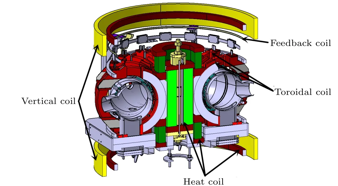
Fig.1. The design structure of HT-6M.

The optimized null field can be reached after adjusting the compensated coils. Figure 2(c) shows that a large region with a small stray field(<10 G)can be reached with the optimized OHF coils,as shown in Table 1. The coordinate before optimization isZband after optimization it isZc.
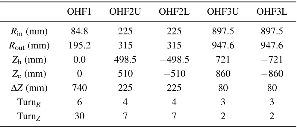
Table 1. OHF coil parameters of the upgraded HT-6M.
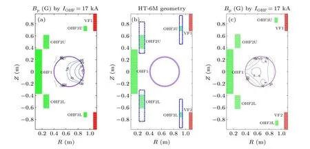
Fig. 2. Position of the ohmic heating field (OHF) and poloidal field distribution. (a) Poloidal field distribution due to OHF coils (IOHF =17 kA)before optimization. (b)Schematic of OHF coil optimization. (c)Poloidal field distribution by OHF coils(IOHF=17 kA)in a small region<10 G.
3. Design of the magnetic sensors
In this section we discuss the design of the magnetic sensors. Table 2 shows the parameters of HT-6M during operation. Figure 3 shows the electromagnetic probe distribution.Each inductive sensor consists of a conducting loop or coil,Rogowski loops,flux loops,magnetic probes and diamagnetic loops;details are described in the following.

Table 2. HT-6M device parameters.
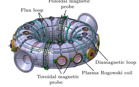
Fig.3. Diagram of the electromagnetic probe distribution.
3.1. Rogowski loops
In HT-6M,in order to measure the toroidal field current,ohmic field current, vertical field current, feedback field current and plasma current, respectively, five pairs of Rogowski coils are installed in the current circuit,according to the device parameters.
A Rogowski coil is an effective tool for measuring instantaneous current.[10]After uniformly and closely winding the skeleton withNturns, the changing current will induce a changing magnetic flux in the skeleton,and the changing magnetic flux will generate an induced electromotive force at the end of the coil.Combined with the Amp`ere loop law and Faraday’s law of electromagnetic induction,the measured voltage is given by

whereitis the current to be measured,sis the cross-sectional area of the Rogowski coil,nis the winding density, which is the number of winding turns per unit length, andMis the mutual inductance estimated fromSandn. As shown in the formula,the cross-sectional area and winding density of a Rogowski coil directly determine the signal quality.
Since the vacuum chamber of a tokamak needs to be baked at 200◦C, the Rogowski coil used to measure plasma current is made of materials that are resistant to high temperatures. The winding fiber inside the coil is made of high temperature resistant enameled wire. The protective sleeve of the outer layer of the coil is made of silica gel. The other Rogowski coils have no special requirements. The mutual inductance coefficientsLof the plasma current coil,PF and TF coils are all 2.71×10⁻⁷H.
To obtain the real physical current the detector circuit is equipped with a self-triggered integrator. A better sensitivity can be obtained by changing the integral constant. In this diagnostic system,theRCconstants of the plasma current Rogowski coil,the ohmic current Rogowski coil,the toroidal Rogowski coil, the vertical current Rogowski coil and the feedback current Rogowski coil are 3.88 ms,0.533 ms,0.247 ms,0.152 ms,and 0.028 ms,respectively.
The plasma current Rogowski coils are toroidally arranged at 0◦and 180◦. The toroidal field,ohmic field,vertical field and HDF field Rogowski coils are arranged around the power bus-line.
3.2. Flux loops
To obtain the loop voltage and measure the horizontal and vertical displacement of the plasma,the flux loops are designed and installed outside HT-6M’s vacuum vessel. The flux loop, arranged on one ring, measures the toroidal loop voltage and poloidal flux loop. The loop voltage can be used for plasma breakdown and for evaluation of plasma discharge parameters. The magnetic flux mainly comes from the plasma current

whereRis the plasma large radius,Sis the plasma crosssection area andσis the parallel conductivity divided by the effective charge number.
To obtain the horizontal and vertical displacement of the plasma, the flux loops are installed on the high-field side
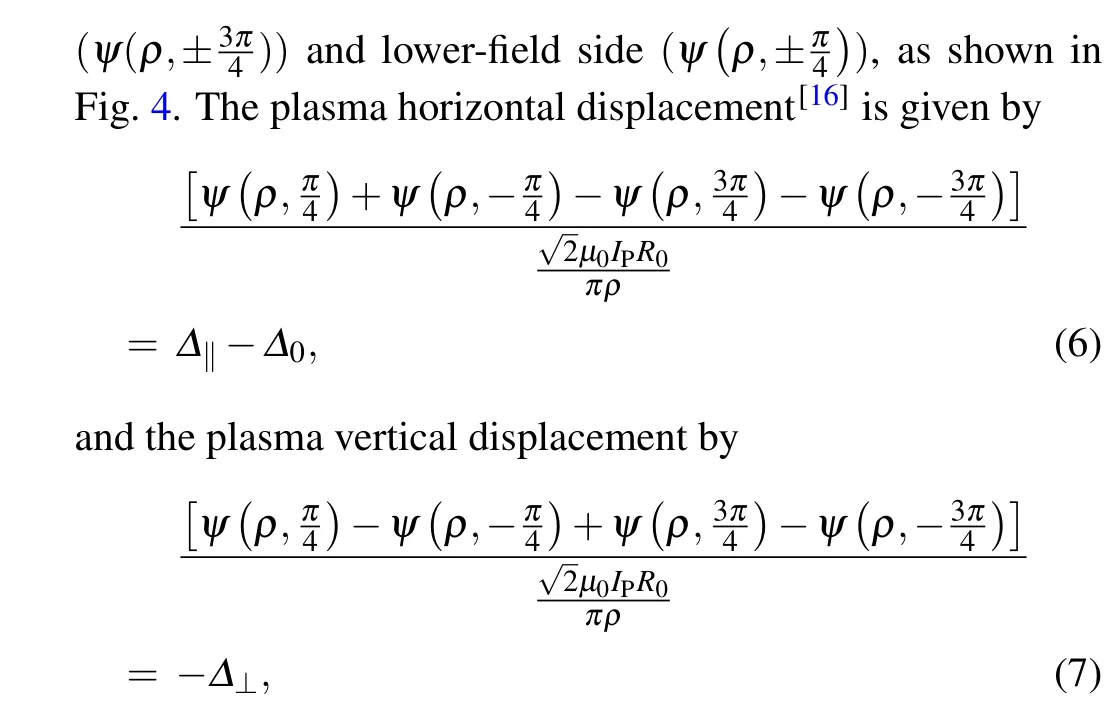
whereψ(ρ,θ) is the plasma magnetic flux,ρis the position in theRdirection,θis the probe angle,∆‖is the plasma horizontal displacement,∆0is the correction introduced by the toroidal plasma current,µ0is the permeability of a vacuum,IPis the plasma current andR0is the distance from the probe to the geometric center.
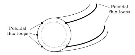
Fig.4. Poloidal flux loop installation diagram.
The flux loops measuring the loop voltage are installed on the middle plane in the high-field side. So as not to be damaged by the high baking temperature, the flux loops are made of polyether ether ketone(PEEK)cable and are fixed inside a stainless steel tube. Since the induced voltage from the flux loop is so high,the matchedRCvalue of the integrator is 200 ms.
3.3. Magnetic probes
To measure the magnetic field and MHD issues(such asm/nmode or mode frequency),the upgraded magnetic probes are usually arranged around the poloidal and toroidal directions of the plasma. According to the law of electromagnetic induction, when a coil in a magnetic field induces a certain voltage, the signal can be integrated to obtain the flux value through the coil region. The magnetic flux can be treated as the magnetic field value with a smaller coil volume than the entire observation space. The formulae are as follows:[11,19]
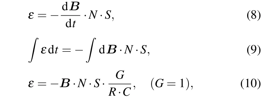
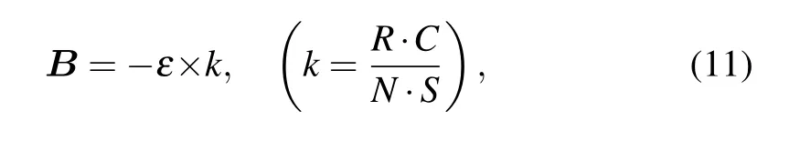
whereBis the magnetic field as measured by the probe,εis the output voltage,Nis the magnetic probe winding number,Sis the induced area of the probe in one turn,Ris the equivalent resistance of the integrator,Cis the equivalent capacitance of the integrator,NSis the effective induced area andRCis the integrator constant.
The magnetic probes are installed in two arrays in different toroidal positions with 180◦symmetry. Each array has 12 probes in the poloidal plane. They are used to measure the poloidal field andm-mode. Sixteen probes arranged in the low-field side and in the equatorial plane are used to measure then-mode.
A larger probe’s effective induced area (NSvalue) will lead to a higher output amplitude. However, due to space restrictions between the vacuum vessel and toroidal field coils,the probe height space is less than 35 mm. Based on experience with tokamak operation, to obtain a high-quality output signal, theNSvalue of the magnetic probes should be larger than 0.1 m2. Finally,the length,width and height of the probe are 36 mm,36 mm,and 20 mm,respectively. The number of turns of the coil in both directions is eight and the corresponding active areaNSranges between 0.12 m2and 0.32 m2. The coil is designed in two dimensions to measure tangential and radial field simultaneously. The tangential field direction measures the polar direction and the radial field direction measures the normal direction. The tangential field and the radial field,respectively, adopt integral constant integrators of 5 ms and 10 ms.
Since the vacuum chamber of the tokamak needs to be baked at 200◦C,the magnetic probes are made of PEEK and the wires of polyimide enameled wire. These materials have a high melting point. Specific design and installation drawings are shown in Fig.5.
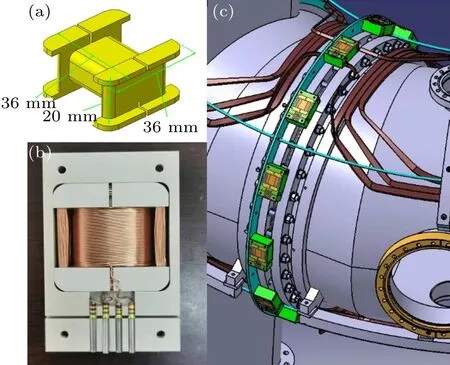
Fig.5. Magnetic probe: (a)diagram of the probe design diagram,(b)photograph of the magnetic field probe,(c)installation position of the polar probe.
3.4. Diamagnetic loops
To evaluate the performance of magnetic confined plasmas and measure poloidal beta(βp),measurement of the diamagnetic flux is achieved by the diamagnetic loops, which consist of one compensation loop excluding the plasma column and two concentric poloidal loops enclosing the plasma column.
The diamagnetic coil is a multi-turn coil around the plasma circular flux. It can diagnose changes in the toroidal flux which are associated with transverse thermal motion of the plasma.
Since the diamagnetic signal is only 10−3–10−4times the toroidal field flux,the diamagnetic compensation measurement system is composed of a diamagnetic coil and a compensation coil, the designs of which are shown in Fig. 6. The system uses the compensation coil signal to compensate the toroidal field signal, which is also measured by the diamagnetic coil,remove the stray signal and obtain the real diamagnetic signal.[12,13]
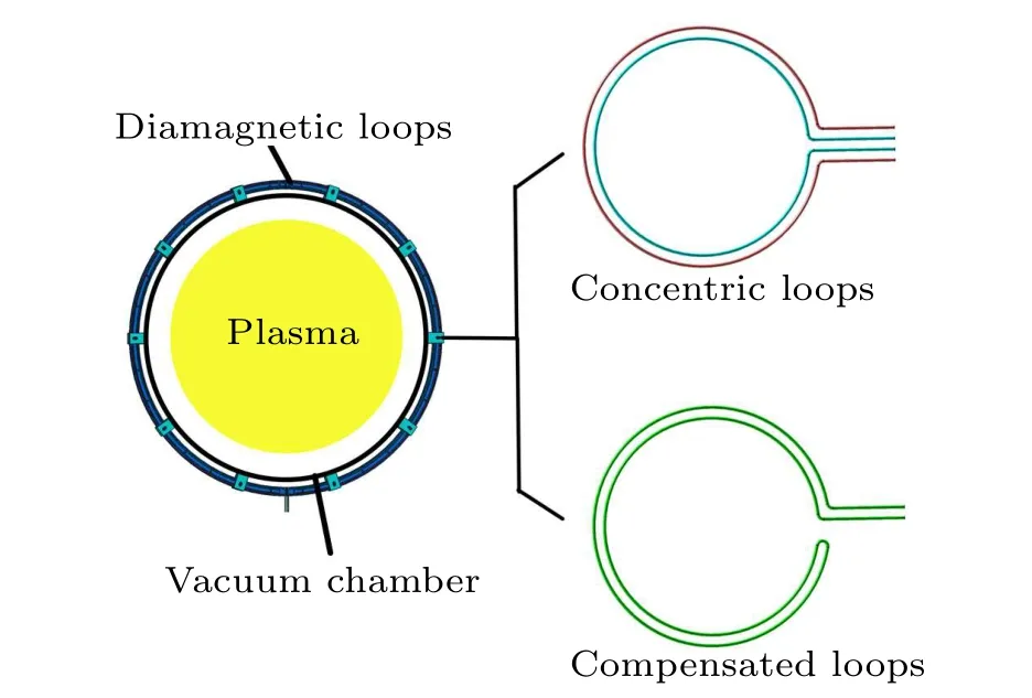
Fig.6. Design of the diamagnetic loops.
The flux linked to the inner loop during a plasma discharge can be expressed as
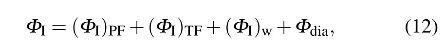
whereΦIis the inner coil total flux, (ΦI)PFis the flux contributed by the ohmic field and vertical field and(ΦI)TFis the flux contributed by toroidal field. Since the poloidal field is theoretically perpendicular to the inner loop, the flux contribution from the PF coil is very small compared with that from the TF coil.Φdiais the flux contributed by the plasma. (ΦI)wis very complicated, as the changed toroidal field will induce a poloidal wall current,giving an extra toroidal flux contribution. This motivated us to add a compensation loop
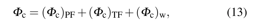
whereΦcis the compensation loop total flux, (Φc)PFis the flux contribution from the poloidal field, (Φc)TFis the flux contribution from the toroidal field and(Φc)wis the flux from the wall current.
The inner flux loop and compensation loop are installed in the same plane,soΦIcan be simplified as
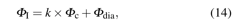
wherek=SI/Sc,SIis the area of the inner coil andScis the area of the compensation loop. In the experiment to check the coefficientk,a series of vacuum shots with TF current will be performed. In HT-6M,the diamagnetic loops have two loops,and the compensation loops have one loop.
4. Calibration of magnetic sensors and experimental results
Calibration of the magnetic sensor system is necessary if we are to obtain actual and accurate physical values for a plasma, such as poloidal field and current. In this section we describe calibration of the magnetic sensors,includingNSvalue measurement,frequency response calibration,Rogowski coil testing andRCvalue calibration. Magnetic sensor experiments with pure poloidal current are described.
4.1. Calibration of magnetic sensors
TheNSvalue calibration TheNScalibration system is tested on a long and straight solenoid. An alternating and uniform magnetic field is generated in the induction area calibration system.[19]The calibration error can reach less than one part in a thousand, and simultaneous calibration of multiple probe coils can be realized. The specific operation block diagram is shown in the Fig.7.
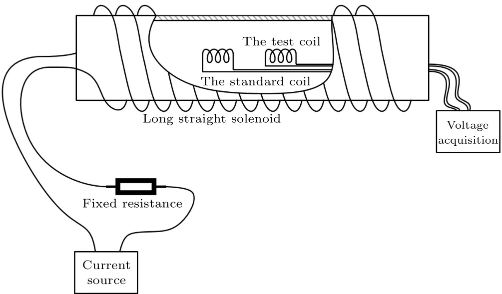
Fig.7. System block diagram for NS value calibration.
Frequency response calibration Due to the special requirements for the discharge parameters of the upgraded HT-6M device, calibration of the frequency response, including amplitude–frequency and phase–frequency calibration,are tested, as shown in Fig. 8(a). The fixing fixture of the probe coil is placed in the Helmholtz coil, so that the probe coil is fixed in the center of the Helmholtz coil. The frequency response bandwidth of the probe is 140 kHz for the inner ring and 120 kHz for the outer ring, which meet operational requirements.
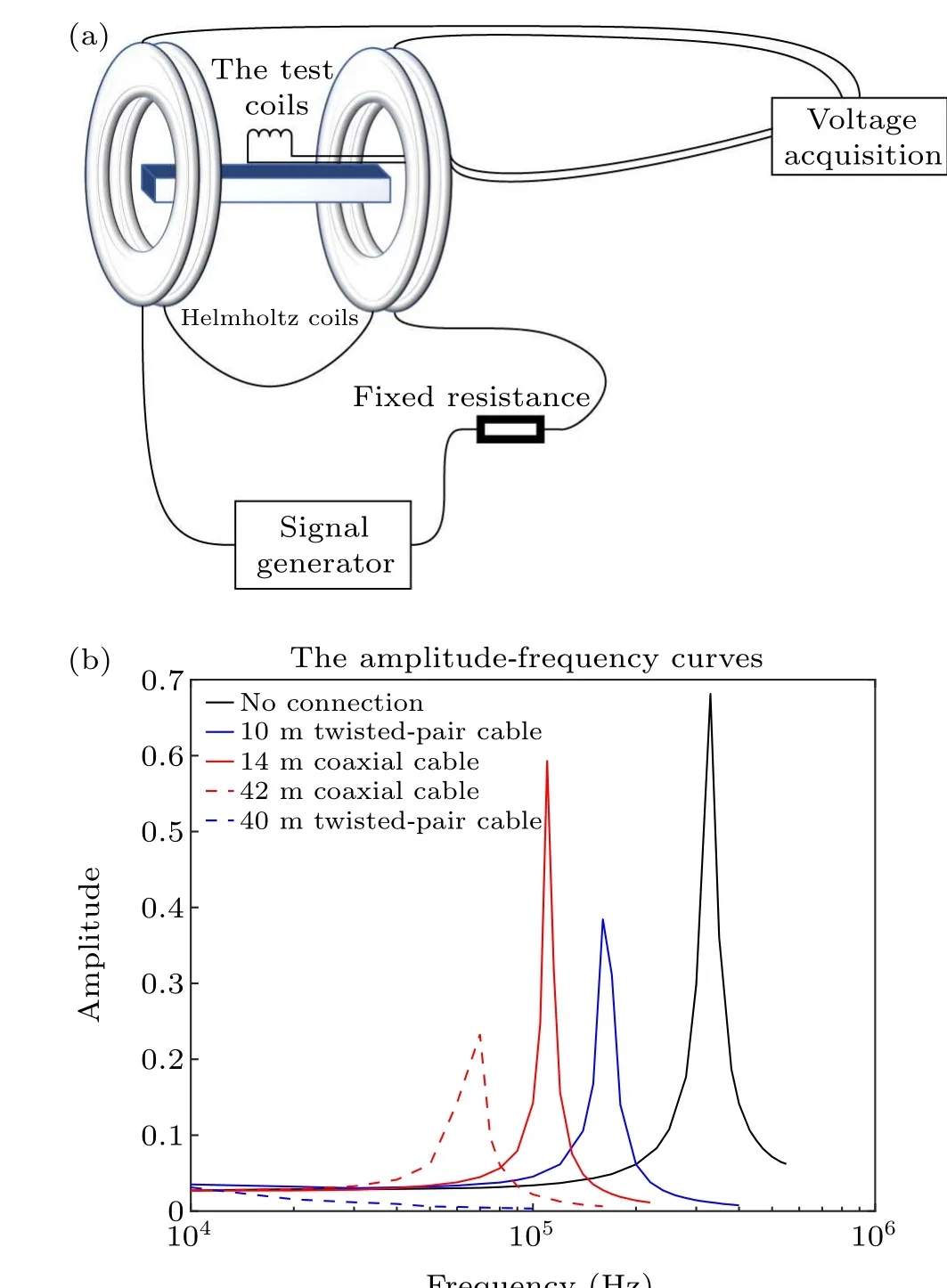
Fig.8. (a)Helmholtz coil calibration diagram. (b)Amplitude–frequency curves.
In the entire signal acquisition circuit, long-distance cable transmission will lead to attenuation of the frequency response.[21]In this calibration,both a twisted-pair cable and a coaxial cable are tested. Figure 8 shows that the resonant frequency gradually decreases with increase in the length of the wire. Furthermore, it is found that the linear region of the amplitude–frequency curve is 50 kHz when 42 m of coaxial cable is connected to the circuit, and the resonance frequency is 70 kHz.When a 40 m twisted-pair wire is connected to the circuit, attenuation of the signal amplitude decreases more rapidly and a resonance frequency is not observed in this case. Therefore,coaxial cable is more conducive to highfrequency signal transmission than twisted pair cable.According to recent experiments, in HT-6M operation, the tearing mode is observed under ohmic heating and the frequency is about 20 kHz–40 kHz. Based on the previous platform test,to meet Thailand’s 100 kHz frequency response requirements,a magnetic probe matched with 5 m coaxial cable is used.
Rogowski coil calibration In order to verify the previously calibrated mutual inductance of the Rogowski coil and ensure the accuracy of magnetic measurement,the coefficient of the Rogowski coil is checked. The Rogowski coil is calibrated through a circuit loop. The circuit current can be obtained by measuring the voltage across the high-power resistors in the circuit(red line in Fig.9). Then a coil with a known number of turns (N·I) is connected in series into the circuit,and the Rogowski coil is used to measure the current of the coil. The output voltage of the Rogowski coil is obtained.By inverse calculation of the output voltage of the Rogowski coil,a calculated value can be obtained. The error is found to be less than 1%compared with the standard current obtained from the resistor. Figure 9 compares the signal size curves obtained through inverse calculation. The red line is the standard current,and the blue line is the inverse calculated value.

Fig.9. Calibration diagram for a Rogowski coil.
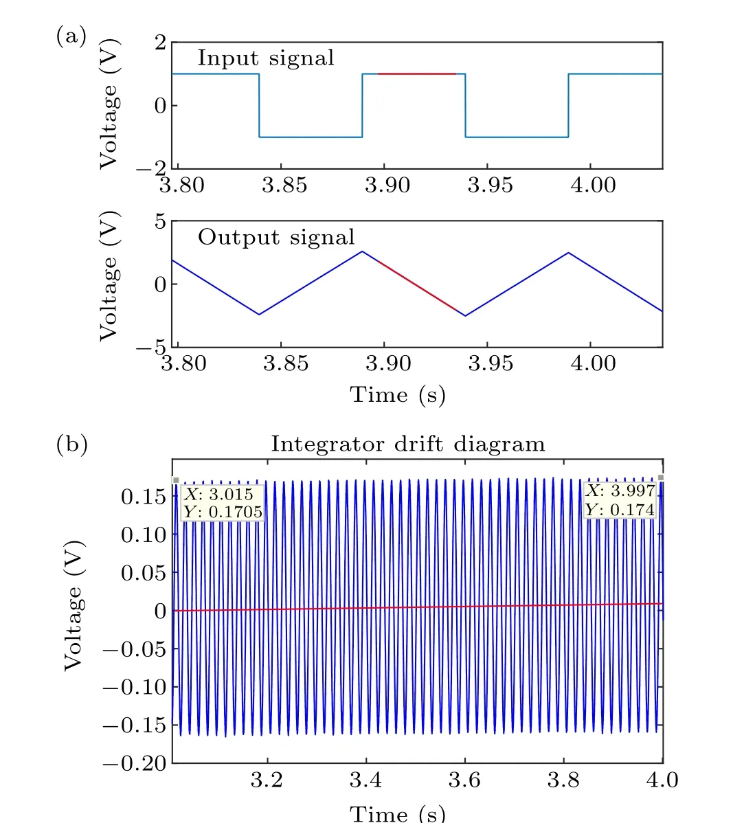
Fig.10. Integrator calibration: (a)RC value calibration,(b)integrator drift.
Integrator constant calibration The time constant(RC)of the integrator is an important parameter of the integrator,and its precision will affect the precision of the system.[22]This calibration adopts the method of inputting a specific signal to the integrator and calculating the integral constant of the integrator through the amplitude of the output signal. The input signal is a standard square-wave signal. As shown in Fig. 10, by inputting a standard square wave signal with an amplitude of 1 V to the integrator, the value ofG/RCis then obtained from the average slope of the resulting triangle-wave output. The integral constantRCcan be obtained from the formula
whereksis the average slope of the resulting triangle-wave output andVinis the input voltage.
The result shows that the integral constant error of the integrator is about 1.5%. In addition, the calibration analysis checks for noise and distortion in the output. The analysis shows that noise is less than 10 mV and drift is less than 5 mV·s−1,as shown in Fig.10(b).

Fig.11. Magnetic diagnostic calibration: (a)calculated and measured flux loops values,(b)calculated and measured magnetic probe values.
4.2. Experimental results for magnetic sensors
After calibration of the Rogowski coils,the current of the PF coil can be accurately measured. Then,the theoretical values for the magnetic probes and flux loops can be calculated by multiplying the measured coil current and response matrix between the PF coils and these diagnostics. The accuracy of the magnetic probe can be verified by comparing the calculated value with the measured value
whereBpis the reconstructed poloidal field of the magnetic probe on the chamber,Gis the response matrix between the OHF coils and magnetic diagnostics andIcis the OHF coil current
whereΦpis the reconstructed poloidal field of the flux loop on the chamber,Gis the response matrix between the OHF coils and magnetic diagnostics,Icis the OHF coils current andNSFLis the flux loop coefficient.
Then, the calculated value for the magnetic field of the magnetic sensors can be obtained from Eqs.(16)and(17).
Figure 11 compares the measured and calculated values in a test discharge. In the 24 shots, the OHF coil current is 15.6 kA and the other coils have no current. Good consistency means perfect installation and calibration of the magnetic diagnostics system.
In order to verify the null field, a fitting code was developed to reconstruct the stray field in the vacuum chamber based on measured values for the magnetic probes and flux loops. The reconstructed OHF coil current can be acquired by least-squares fitting based on
whereIcis the OHF coil current,GCDis the response matrix between OHF coils and the magnetic diagnostics andDis the measured value for the magnetic diagnostics.
After obtaining the OHF coil current, the poloidal field distribution in the vacuum chamber can be calculated by
whereBpis the reconstructed poloidal field in the chamber,GCPis the response matrix between the OHF coils and calculated grids in the chamber. As shown in Fig.12,a large region with a small stray field (<10 G) can be achieved, which is consistent with the desired null field in the device optimization phase. A comparison of the measured and reconstructed OHF coils is shown in Fig.11. Consistent results verify good null field optimization.
Figure 13 shows that the 20 G region basically covers the whole vacuum chamber during the period from 340 ms to 360 ms with an OHF coil current of only 15.6 kA,which is favorable for subsequent plasma breakdown.
The result shows that the error between the calculated electromagnetic measurement and the measured value is not large,basically<1.5%. It lays a solid foundation for the good discharge conditions in the experiments.
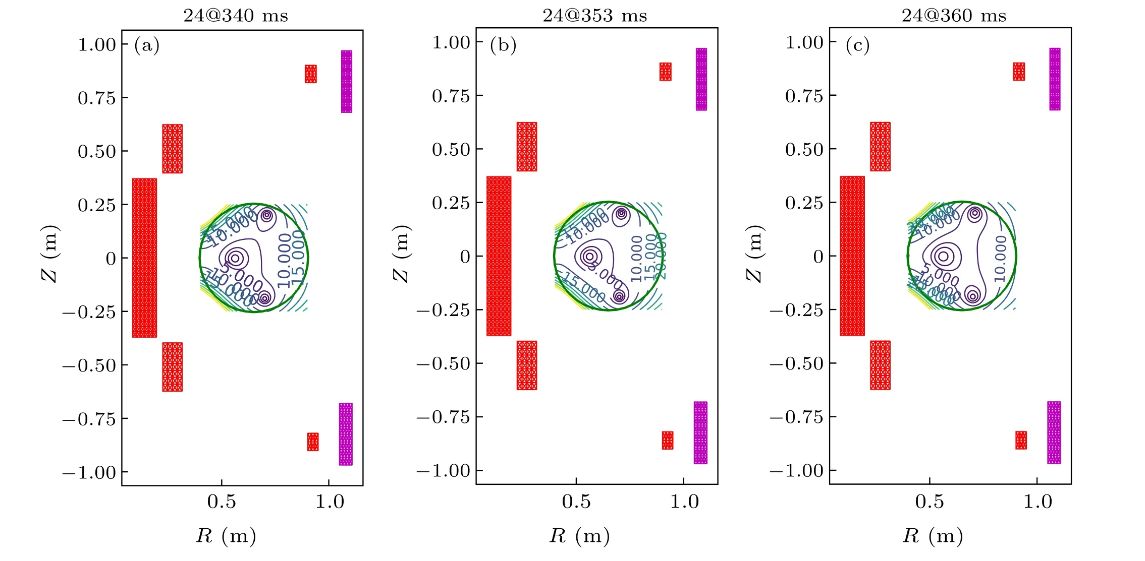
Fig.12. Vacuum field configuration inversion.

Fig.13. The 24-shot calculated and measured values.
5. Summary
As an indispensable part of the tokamak diagnostic process,magnetic diagnostics are the most effective means to obtain device engineering parameters and internal plasma information by using the principle of electromagnetic induction.Its main functions are: (i) protection of device safety, (ii) provision of input parameters needed for device operation and real-time control, (iii) experimental physics studies of MHD behavior,plasma rupture physics and so on.
In this article, the original HT-6M device was first modeled and calculated. The previous device parameters could not meet the design requirements for perfect plasma zero field. The position of the ohmic field coils(OHF2U,OHF2L,OHF3U,OHF3L)was optimized,and a perfect zero field obtained. The third part involved designing an arrangement of magnetic probes including a Rogowski coil, flux loop ring,magnetic probe and diamagnetic coil. Finally, the calibration and experimental results of the magnetic probes are described:NSvalue,frequency response,integral constant(RC)of the integrator, zero drift and the calculated and measured values of the total experimental Green’s function of the magnetic probe are compared. It is demonstrated that the measurements are in good agreement with the modelling, which indicates that the magnetic system works well. After the reconstruction of the vacuum field shape during the discharge test, it is found that a 20 G area basically covers the whole vacuum chamber, which is quite reasonable for subsequent plasma breakdown. Finally, by reconstructing the plasma equilibrium, a better PF coil comparison result is obtained, which can meet the discharge requirements. In recent experiments, the upgraded tokamak has shown a smooth breakdown with optimized null field,and a discharge above 50 kA for longer than 100 ms has been achieved.
Acknowledgments
The authors acknowledge Xueqin Li and Jun Wei for helpful discussions about the design of the magnetic probe.
Project supported by the National MCF Energy Research and Development Program of China (Grant Nos.2018YFE0302100 and 2018YFE0301105),the National Natural Science Foundation of China (Grant No. 11875291),and the Comprehensive Research Facility for Fusion Technology Program of China (Grant No. 2018-000052-73-01-001228).
猜你喜欢
Plasma Science and Technology(2022年8期)2022-09-14
中国德育(2022年12期)2022-08-22
意林彩版(2022年1期)2022-05-03
Chinese Physics B(2022年4期)2022-04-12
今日农业(2021年13期)2021-11-26
作文评点报·低幼版(2020年27期)2020-07-23
民族学刊(2020年1期)2020-06-11
小天使·一年级语数英综合(2019年8期)2019-08-27
金桥(2018年12期)2019-01-29

- Chinese Physics B的其它文章
- Editorial:Celebrating the 30 Wonderful Year Journey of Chinese Physics B
- Attosecond spectroscopy for filming the ultrafast movies of atoms,molecules and solids
- Advances of phononics in 20122022
- A sport and a pastime: Model design and computation in quantum many-body systems
- Molecular beam epitaxy growth of quantum devices
- Single-molecular methodologies for the physical biology of protein machines