
Structure and material study of dielectric laser accelerators based on the inverse Cherenkov effect
2023-10-11 07:55BinSun孙斌YangFanHe何阳帆RuoYunLuo罗若云TaiYangZhang章太阳QiangZhou周强ShaoYiWang王少义DuWang王度andZongQingZhao赵宗清
Chinese Physics B 2023年9期
Bin Sun(孙斌), Yang-Fan He(何阳帆), Ruo-Yun Luo(罗若云), Tai-Yang Zhang(章太阳),Qiang Zhou(周强),6, Shao-Yi Wang(王少义), Du Wang(王度), and Zong-Qing Zhao(赵宗清)
1Department of Plasma Physics and Fusion Engineering,Key Laboratory of Geospace Environment(Chinese Academy of Sciences),University of Science and Technology of China,Hefei 230026,China
2Laser Fusion Research Center,China Academy of Engineering Physics(CAEP),Mianyang 621900,China
3The Sciences and Technology on Plasma Physics Laboratory,CAEP,Mianyang 621900,China
4Institute of Fundamental and Frontier Sciences,University of Electronic Science and Technology of China,Chengdu 610054,China
5Department of Nuclear,Plasma,and Radiological Engineering,University of Illinois at Urbana-Champaign,104 South Wright Street,Urbana,IL 61801,USA
6CAS Key Laboratory of Quantum Information,University of Science and Technology of China,Hefei 230026,China
7The Institute of Technological Sciences,Wuhan University,Wuhan 430072,China
Keywords: dielectric laser accelerator,high gradient accelerator,inverse Cherenkov effect,accelerated structure and material
1.Introduction
Particle accelerators have been used for a variety of purposes beyond basic research since their invention in the 20th century.[1,2]They have been instrumental in advancing many fields including material science, solid state physics, biology, chemistry, geology, and archaeology, as well as industrial, agricultural, and medical applications.However, traditional radio-frequency(RF)accelerators are often large,heavy,and expensive due to the low breakdown threshold of metallic structures and power limitations of microwave sources.[3–6]This has led researchers to explore more affordable and compact accelerating solutions.[7–13]
One such solution is the dielectric laser accelerators(DLAs), which is based on laser-dielectric material interaction and has attracted increasing interest in recent years.[14–20]DLAs can achieve acceleration gradients exceeding 1 GV/m,which is significantly higher than those in conventional accelerators.[21–23]It has the potential to revolutionize electron microscopes, colliders, and attosecond particle, and radiation sources.[24–26]In DLAs, particles (usually electrons) can be accelerated by designing dielectric materials to modulate the incident laser.Thus,an important research direction is selecting materials and designing structures for laser modulation in DLAs.
The current DLAs is mainly based on the inverse Smith–Persell effect (ISP-DLAs), and there are many accelerated structures based on this theory,such as various common grating or photonic crystal accelerated structures.[27–29]However,in the current research,ISP-DLAs has encountered some challenges.For instance, the accelerated structures need to be prepared by advanced micro and nano processing techniques;they also need to be fabricated using dielectric materials with high laser damage threshold, usually SiO2, due to its mature micro and nano processing means.At the same time, materials such as Al2O3, which have higher laser damage threshold but cannot be micro-nano-processed, cannot be applied.Furthermore, the laser damage threshold of the micro-nanoprocessed structures will be reduced, which will further limit the acceleration gradient.Additionally, long-range acceleration faces many problems, such as phase matching, energy utilization efficiency,and the need for laser pulse front tilting techniques.To address these challenges,researchers have proposed an alternative approach based on the inverse Cherenkov effect(ICA-DLAs).However,the current ICA-DLAs is still in its infancy,with relatively few structures and materials used,a lack of optimization studies on structures,and the need to explore other materials with high laser damage thresholds.[30–34]
Our study proposes several dielectric laser accelerator(DLAs)structures based on the inverse Cherenkov effect,and we compare four materials using simulations.Our designs are experimentally feasible and enhance the acceleration gradient and energy gain compared to earlier ICA-DLAs structures.They are suitable for accelerating electrons from sub-relativity to the relativistic state.These structures are also straightforward and require less processing, making it possible to use a wider range of materials compared to ISP-DLAs structures.[27]Our research findings will contribute to future studies on compact accelerators,and researchers can leverage these structures and materials to achieve larger acceleration gradients.
2.Accelerator simulation design
Figure 1 illustrates the three primary structures analyzed in this study.The structures are designed with two laser beams that strike the prism’s surface vertically and simultaneously from both sides, while the electron beam advances along thexaxis in a vacuum channel.Structure A,depicted in Fig.1(a),employs a dielectric prism with an inverted right triangle cross-section.Structure B,illustrated in Fig.1(b),uses a prism with a right triangular cross-section.Structure C,shown in Fig.1(c),has a parallelogram cross-section.Figure 1(d)depicts the correspondence of the three structures.The length of the bottom edge of all three structures isL,the angle between the left beveled edge and the bottom edge isα, and the angles between the right beveled edge and the bottom edge areθ1,θ2, andθ3, respectively.The angles satisfy the relationsθ1=π/2-α,θ2=π/2, andθ1=π-α.As a result, the structures under the structure A evolved into structures B and C,respectively.
To investigate the acceleration of electrons, twodimensional three-velocity (2D3V) simulations based on finite-element-method (FEM) and particle-in-cell (PIC) algorithms were employed.The electric field strength was set toE0=6 GV/m, and the laser wavelength was selected as 800 nm,which is the most widely wavelength for DLAs studies.In the simulation, continuous-wave(CW)mode was employed.The vacuum channel had a length ofL=10λand a width ofC=λ/4, which was suggested in a prior DLAs study.[27,28]The angleαwas given byα=arcsin(1/nβ).The initial kinetic energy of the electrons injected in the simulations spanned from 300 keV to 1000 keV, andβwas the relativistic velocity corresponding to the energy.This energy interval was chosen because after higher than 1000 keV,βdoes not change much and therefore the structure does not change much; while below 300 keV, the corresponding pinch angleαfor some materials is too high and basically unsuitable for acceleration.The monoenergetic electron beam’s charge was approximately 10.7 fC,and there was no initial energy spread.With a spatially KV distribution,the initial longitudinal beam length equates to 0.27 fs and the initial transverse dimension was 0.16 μm.The KV distribution placed particles uniformly in phase space.The distance between particles was roughly the same throughout the beam.The initial normalized emittance was 103pm·rad.Four materials were used in this study,and the material refractive indices used in the simulations were divided intonSiO2=1.45,nAl2O3=1.76,nY2O3=1.91, andnZnO2=2.14.[35–38]

Fig.1.Schematic diagrams of the cross sections of the three main structures studied and comparisons.In(a)–(c),the dielectric structure is depicted in green,the vacuum channel that accelerates electrons within the dielectric structure is depicted in orange, and the laser is depicted in red.Structure A has a right triangle with its cross section flipped,while structure B has a standard right triangle.Structure C has a parallelogram.The comparison of the three individual structures is shown in panel(d),where dark blue designating structure A, light blue designating the portion added to structure B relative to structure A, and blue–green designating the portion added to structure C relative to structure B.
3.Simulation results and discussion
Figure 2(a) illustrates how the acceleration gradient changes as electron energy changes for various materials and structural configurations.First, for all three configurations of the four materials, the acceleration gradient rises as electron energy rises.This is because when the electron energy increases,the structural pinch angle reduces,and earlier studies have shown that the pinch angle may be decreased to enhance the acceleration gradient.[30,31,34]Second, withGB≈GC≥GA, the acceleration gradients of the B and C structures are comparable and both are higher than the acceleration gradient of the A structure.
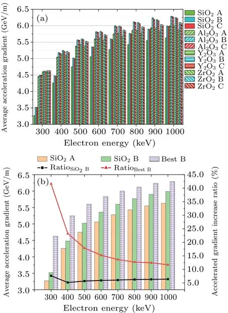
Fig.2.(a) After the combination of four materials and three structures,the acceleration gradient varies depending on the energy of the input electron in each scenario.Structures A,B,and C are represented by the hues dark green, vivid blue, and red, respectively.The horizontal transverse stripe,oblique down-left stripe,oblique down-right stripe,and unshaded pattern all stand for SiO2,Al2O3,Y2O3,and ZrO2,respectively.(b)The results of the accelerated gradients of the best materials utilizing Y2O3 and Al2O3,respectively,with the combination of B structures at each interval.The accelerated gradients of the combination of A and B structures of SiO2 materials.SiO2 and structure A’s acceleration gradient is represented by the color orange, SiO2 and structure B’s acceleration gradient is represented by the color light green, and the acceleration gradient for the best material and structure B is represented by the color purple with a square pattern.The improvement of the SiO2 and structure B combination over the SiO2 and structure A combination is shown by the black line with a square in it.The improvement of the best material and structure B combination is depicted by the red line with the triangle in it.
This is due to the disordered electric field caused by structure A’s left-side boundary effect and the existence ofθ1(acute angle).Structure A is the same as the left side of structure B and structure C.The problem of structure A arises from the difference in the right side.First, because the right side of structure A is downward slanted to the left, resulting in the laser on the bottom surface being fully reflected back to the slant,part of the laser will be reflected back to the bottom surface, and the electric field on the bottom surface superposes,affecting the amplitude and phase of the accelerating field on the bottom surface,thus affecting the acceleration of electrons;second, the right side of structure A has a sharp acute angle,which will lead to field disorder in the vicinity of this acute angle.In addition,in the actual process,the sharp angle configuration will increase processing difficulty,and the enhanced field here will make the medium easier to be penetrated by the electric field,meaning that the actual acceleration of the laser intensity will be lower in structure A compared to structure B.Furthermore,there is not much of a difference between structures B and C,in some cases,structure B may even be better.This suggests that structure B, which has a smaller structure and an easier-to-process form,can address some of the issues with structure A.
The effect of material on the acceleration gradient is compared for all the same structures.SiO2has a smaller acceleration gradient than the other three materials.At lower energy(300 keV–600 keV),GY2O3>GZrO2>GAl2O3, and at higher energy(700 keV–1000 keV),GAl2O3>GY2O3>GZrO2.These variations result from the fact that, as the refractive index increases, the angle decreases, making it possible to raise the ratio of the dielectric electric field strength to the accelerated electric field strength in the vacuum channel.However,as the refractive index increases,the transmittance decreases and the electric field strength in the dielectric decreases,resulting in a decrease in the electric field strength in the vacuum channel.Therefore, greater refractive indexes are not necessarily better,and models and calculations must be used to determine the ideal dielectric material.To obtain the maximum acceleration gradient, the appropriate dielectric material must be chosen based on the size of the electron energy.
The enhancement of the acceleration gradient is improved under structures B and C made of different materials in comparison to that under structure A made of corresponding material.The acceleration gradient can be raised for all materials by changing the structure, but for SiO2materials, especially at 300 keV, where the large pinch angle is present, the acceleration gradient can be raised to the greatest extent.The results of the combination of the best material (using Y2O3or Al2O3, respectively) with the B structure at each interval are shown in Fig.2(b), along with the acceleration gradients based on the combination of the A and B structures of SiO2material.Additionally,it displays the gradients of acceleration for the combinations of SiO2and structure A as a benchmark,SiO2and structure B, and optimum material and structure B,respectively.SiO2and the structure A are the material and structure most frequently employed.The acceleration gradient can be increased by up to 41.6%with the combination of the best material and the structure B, or an acceleration gradient of 4.6 GeV/m, while the least enhancement is 11.7%,or an acceleration gradient of 6.3 GeV/m.Meanwhile,an improvement of up to 7.6%and a minimum of 5.2%can be made even without changing the material by switching the structure to a B structure.In addition,SiO2has no advantage over other materials in terms of acceleration, but it is a common DLAs material, due to the fact that materials such as Al2O3cannot be finely processed as SiO2.All three structures compared in this article do not require fine processing,thus contributing to the study of DLAs and also giving these materials the opportunity to be used in scenarios.

Fig.3.(a)Schematic diagram of structure D.The original structure D is shown in light blue, while the portion of structure B that was destroyed is shown in dark blue.Figure 1-like whole accelerated design concept is depicted in the drawing attached; (b) The variation in incident electron energy and how it affected the acceleration gradient for each of the four materials and combinations of the two structures.Structure B and structure D are represented by the vivid blue and earthy yellow hues,respectively.The filling designs match the materials as seen in Fig.2(b).(c)The results of the accelerated gradients of the best materials utilizing Y2O3 and Al2O3, respectively, with the combination of D structures at each interval.The accelerated gradients of the combination of A and D structures of SiO2 materials.SiO2 and structure A’s acceleration gradient is represented by the color orange,SiO2 and structure D’s acceleration gradient is represented by the color bright yellow, and the acceleration gradient for the best material and structure D is represented by the color the blue stripe.The improvement of the SiO2 and structure D combination over the SiO2 and structure A combination is shown by the black line with a square in it.The improvement of the best material and structure D combination is depicted by the blue line with the circle in it;(d)The left and right diagrams show the schematic diagrams of structure E and structure F,respectively.
Additionally,the upgraded structure using the structure B as the fundamental model was also researched for comparison because of its superiority over the other two structures.The three structures shown in Figs.3(a)and 3(d)provide the best results.Structure D is based on structure B in Fig.3(a).Only two incident laser wavelength lengths are present on the right vertical side,and similarly to how structure A was handled,a vertical line is drawn on the opposite side.These two incident laser wavelength lengths were used because,following extensive simulation optimization, this was the best outcome.The right side of the left side structure E in Fig.3(d)is treated by circularizing it,with the radius being equal to the lengthLof the bottom edge and the center being the vertex of the angle.The right-hand structure F in Fig.3(d) is a symmetric structure with both the beveled edge and the lower bottom edgeL.The right-hand vertical edge is the same length as the upper bottom edge,and both sides are perpendicular to the lower bottom edge and the beveled edge,respectively.
The accelerated gradient results for the four materials in the structure D are shown in Fig.3(b).The acceleration gradient of the structure D is stronger than that of the structure B,and the difference caused by the material is also consistent with Fig.2.Using the combination of SiO2and structure A as a benchmark, figure 3(c) illustrates the enhanced magnitude of the combination of SiO2and structure D as well as the combination the of optimum material and D structure.The results show that the highest acceleration gradient enhancement,which corresponds to an acceleration gradient of 4.69 GeV/m,can be reached by the combination of the optimal material and D structure.The lowest acceleration gradient enhancement corresponds to an acceleration gradient of 6.40 GeV/m.While maintaining the same material, replacing the structure with a D structure can result in an enhancement of up to 11.3%and as little as 8.5%.
4.Conclusion and perspectives
In summary, this article investigates six structures and four materials for use in dielectric laser acceleration based on the inverse Cherenkov effect in the energy range from 300 keV(subrelativity) to 1000 keV (relativity).The investigation reveals that the structure with the largest average acceleration gradient among them is the combination of optimum material and D structure.This study also provides the best among the four materials for various initial electron energies, which can serve as a foundation for choosing materials for subsequent laser dielectric acceleration investigations.Furthermore, this study demonstrates that by utilizing the ideal mixture of materials and structures,larger acceleration gradients and energy gains can be obtained.These findings will serve as a starting point for future research on-chip accelerator structures in subrelativity to relativity acceleration.
Acknowledgements
The authors thank Dr.Bin Zhang of Tel Aviv University, Dr.Wei Li of the University of Science and Technology of China, and Dr.Lai Wei of Laser Fusion Research Center,CAEP,for the insightful discussion.
Project supported by the National Natural Science Foundation of China(Grant No.11975214).
猜你喜欢
职工法律天地·上半月(2020年8期)2020-09-21
分忧(2020年5期)2020-05-11
微型小说选刊(2019年5期)2019-09-10
做人与处世(2018年22期)2018-12-21
鸭绿江(2018年7期)2018-11-12
上海故事(2018年12期)2018-01-07
科学大众·小诺贝尔(2017年4期)2017-08-18
小天使·一年级语数英综合(2017年6期)2017-06-07
学苑创造·A版(2017年4期)2017-05-13
小天使·一年级语数英综合(2015年8期)2015-07-06

- Chinese Physics B的其它文章
- Dynamic responses of an energy harvesting system based on piezoelectric and electromagnetic mechanisms under colored noise
- Intervention against information diffusion in static and temporal coupling networks
- Turing pattern selection for a plant–wrack model with cross-diffusion
- Quantum correlation enhanced bound of the information exclusion principle
- Floquet dynamical quantum phase transitions in transverse XY spin chains under periodic kickings
- Generalized uncertainty principle from long-range kernel effects:The case of the Hawking black hole temperature