
Electromagnetically induced transparency via localized surface plasmon mode-assisted hybrid cavity QED
2023-12-02 09:22XiaomiaoLi李晓苗FaminLiu刘发民ZigengLi李子更HongyanZhu朱虹燕FanWang王帆andXiaolanZhong钟晓岚
Chinese Physics B 2023年11期
关键词:李子
Xiaomiao Li(李晓苗), Famin Liu(刘发民), Zigeng Li(李子更), Hongyan Zhu(朱虹燕),Fan Wang(王帆), and Xiaolan Zhong(钟晓岚)
School of Physics,Beihang University,Beijing 100191,China
Keywords: quantum optics,electromagnetically induced transparency,all-optical switching,localized surface plasmon
1.Introduction
Electromagnetically induced transparency (EIT) is a quantum interference phenomenon where an electromagnetic field controls the response of a three-level quantum emitter (QE) to a probe field, i.e., the ensemble system can be switched from an initially opaque state to a transparent state depending on the control field.[1]The destructive interference strongly depends on the ground-state coherence and will result in the characteristic dark states.The characteristic super slow light velocity of the dark state makes many effects possible,such as slow light,[2,3]quantum memory[4,5]and quantum cooling.[6,7]
In addition, through tuning the dark and bright states,more research is focused on the EIT effect which provides a highly efficient optical switch[8–15]based on a cavity quantum electrodynamics (QED) system in a quantum information network,[16]especially in long-distance transport.[17]As a high-performance optical switch, switching contrast is one of the most important factors in optical networks.A completely transparent or opaque result means that the system can selectively allow or reject transport for a specific signal.An important class of schemes for quantum communication and computing is based on one-sided and two-sided systems.On the one hand, highly efficient quantum memory and perfect photon absorption have been demonstrated in onesided cavity QED systems which meet an impedance-matched condition.[18–20]Nevertheless,high switching contrast has not been obtained in one-sided cavity QED systems for high cooperativity of the systemC=g2/(2κγs) (gis the QE–cavity coupling strength,κis the decay rate of the cavity andγsis the dephasing rate of the QE).Therefore, this one-sided system hinders multitasking devices including transistor action and quantum storage.[21]However, the elimination of perfect absorption in the two-sided system owing to the EIT effect has been achieved theoretically excited by two coherent light fields from two mirrors.[22]Notably,good transparency may turn off the control field fast enough,but make quantum storage inefficient.Hence,improving the high and stable switching contrast and manipulating the EIT effect remain to be elucidated in the one-sided cavity QED system.
Then, exploring the system and how to manipulate the coupling strength and improve switching contrast in the expanded cavity QED is primary.In our previous work, we found that when the light is strongly coupled with two different emitters, a cascade frequency-dependent dual Rabisplitting can be achieved by adjusting the cavity mode reflecting the cavity-molecule detuning.[23]Importantly, Doelemanet al.and Hoanget al.have reported a great deal of promising phenomena in plasmon–photon cavity systems, such as cooperative Purcell enhancements and ultrafast spontaneous emission.[24,25]Thus, it provides the possibility that through manipulating the coupling strength in a hybrid plasmon–photon cavity QED system, the dark and bright states can be flexibly switched resulting in a variable output frequency.The nanometer-sized metal nanoparticle(MNP),as one of the potential candidates,has many unique advantages.
Firstly, the localized surface plasmon (LSP) mode does not require wave vector compensation and generates a subwavelength localized mode because of the much smaller mode volume with deep subwavelength order.[26–29]Secondly, the switching time is a potential challenge in the traditional cavity QED-based optical switch limited by the QE–cavity interaction strength via tuning their spectral overlaps.[14]By means of adding an MNP structure, a three-spectral overlap can be achieved because the coupling strength of the system is boosted greatly dependent on the more confined field of the LSP mode and then the radiative rate of emitters is increased to a great extent.[30–32]Particularly,in the LSP modeprovided cavity QED, the stronger coupling strength of the MNP–QE interaction than the microcavity–QE interaction is shown in Refs.[33,34] due to the much lower mode volume of the LSP mode,which can achieve lower-threshold lasing in the latter.[33]Hence, quantum plasmonics, as a new research field, exhibits very attractive prospects in quantum information,plasmonic quantum lasers and highly sensitive detection,etc.[35]
Here, we propose an all-optical switch designed by the LSP mode-assisted cavity QED system,which is composed of a three-level state(3LS)QE and a metal nanosphere confined in the center of a cavity.In this one-sided system,flexible and variable frequency of transmitted light is accessible by changing the intensity of the control field and the detuning of frequencies.In addition,high and stable switching contrast could be implemented showing the switching on/off state by the control field, which is vital for chip-based quantum communications and fiber-based long-distance transport.In particular,we employ a precise quantum interference explanation to demonstrate the occurrence of a converted dark state.Ascribing to multiple interactions of three modes, three systematic states are formed.Afterward, two transition pathways are formed primarily passing through one same systematic state, resulting in the destructive interference and a dark state without the control field.Then the dressed state of the QE is produced by the resonant control field and the dark state is eliminated.The evolution is analyzed based on the Heisenberg–Langevin (HL)equation and input-output relation which is well consistent with the master equation.
2.General model
We study the LSP mode-assisted hybrid cavity QED system interacting with a 3LS QE as shown in Fig.1(a).The system consists of a single-mode cavity and evanescent field provided by a metal nanosphere (MNP) which are tuned in resonance with each other.
The QE is assembled onto the MNP surface with a fixed distancedby manipulating the optical trap with a highly focused laser.[36,37]The hybrid structures are adjustable in an optical microcavity.Here the radius of the MNP isR=10 nm to ensure that plasmonic resonance approximates the Lorentzian line shape.The mode volume of the MNP is much smaller than the cavity by an amount of order(∼5)to break the diffraction limit.[26]The selection principle of the MNP surface–QE distance is a compromise between avoiding quenching and producing a more confined field.For this purpose, it is prudentially selected asd=10 nm referring to quenching distance,and provides the potential for ultrafast photon emission.[38]
Under the dipole approximations,the Hamiltonian of the composite system can be written asH=H0+HI+Hdrivewhich is given by
The ground state|1〉 and the excited state|3〉 with the excitonic transition frequencyω31are coupled to the microcavity and the LSP mode with the coupling strengthg1andg2,respectively.Mode enhanced factorJis the coupling strength due to the superposition of the vacuum and confined evanescent field between the microcavity and the MNP.
The microcavity–LSP and QE–LSP (microcavity) couplings are described within the rotating-wave approximation(RWA) with the input operator defined by the unitary operator exp[-iω0H0t], i.e.,O(t)(O=a,b)is replaced byO(t)→Oeiω0t.The RWA is valid provided that the following criteria are satisfied:ωc-ωm≪ωc+ωm,ω12(23)-ωc≪ω12(23)+ωc,J ≪ωc,ωm, andg1(2)≪ωc,ωm,ωi j(i,j=1,2,3).The hybrid system is described by the Hamiltonian
where the detunings are defined as the transition of QE–probe detuning∆0=ω0-ω31,microcavity–QE detuning∆c=ωcω31,and control frequency detuning∆23=ωp-ω23.The frequency of the LSP mode and microcavity fields is regarded as the same all the time (ωc=ωm).Compared to the traditional cavity-induced EIT,[39]the major difference lies in the mode enhanced factorJbetween the microcavity and the plasmon mode through introducing the MNP into the microcavity.The frequency of the microcavity and transition|3〉↔|1〉 of the QE is resonant, i.e., the detuning∆c=0.Moreover, our model can provide a distinct method to control EIT and optical switching simultaneously.
2.1.Steady-state analytical solution
We introduce the significant damping Hamiltonian term of the open systems as presented in Ref.[40],which includes the heating loss of the bath and the interaction with considered system components.Then the terms are given as
wheremandnare defined as the radiative decay due to the mode radiative output and the nonradiative decay due to ohmic losses of the open environment,which obey the commutation relation [m,n]=0, respectively.The reservoirsT1–T3represent the coupling strength between the reservoir and the microcavity, the MNP and the QE.Substituting Eq.(3) into the Heisenberg–Langevin equations of motion,the dynamic equations of a coupled microcavity-MNP-QE system are given as
where operators denote the expectation valueO=〈O〉on the left side of the equation.κ1=πT21,κ2=πT22,γs=πT23=(γ32+γ31)/2 represent the decay of the microcavity mode,the sum of the ohmic loss and the dephasing rate of the MNP and the dephasing rate of the QE.Moreover,fa,fb,f13,f23,f12,f11,f22andf33are the noise operators which are derived from the reservoir interaction and reservoir modes which satisfy commutation relation at all times.σz=σ33-σ11is the population inversion of the QE.The Langevin noise operators have zero mean values by assumption in this treatment,as shown already in earlier works.[40]When the system is at the initial point,the great majority of the population of the QE distribute in the|1〉 state, i.e., (σ11≈1,σ22=σ33≈0).The steady-state solutions of Eq.(4) can be readily obtained analytically.The analytical solution of the cavity modeais given as
2.2.Numerical description
In general,the properties of the entire system can be obtained numerically by replacing Eq.(3)with the master equation as
Then,we elucidate how the LSP mode-assisted one-sided system manipulates and changes the characteristics of the photon emitting cavity and switching contrast with a control field.We also quantitatively discuss the quantum interference effect of the variable frequency of output light (VF-EIT) and traditional EIT by the presence and absence of the MNP structure,respectively.
3.Results and discussion
3.1.Characteristic output properties
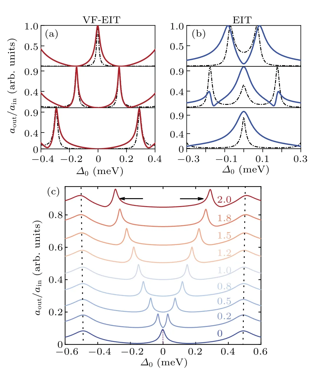
Fig.2.For the (a) variable frequency EIT (VF-EIT) (red line) and (b) traditional EIT (blue line), the output intensity of the MNP-assisted system and traditional cavity QED system numerically (solid line) and analytically (dot line)based on the H-L and master equation with Ω =0,Ω =1 meV and Ω =2 meV (from top to bottom panels).(c) Selective frequency in the VF-EIT with tuning strength of control field Ω =0–2 meV.A pair of bright modes are plotted(dark dashed line).Other parameters are{κ1,κ2,γs,γ21,η,g1,g2,J}=0.07,0.7,0.086,0.002,0.1,0.0206,1,2.9 meV for (a).Other parameters are{κ1,κ2,γs,γ21,η,g1,g2,J}=0.07,0,0.086,0.002,0.1,0.15,0,0 meV for(b).
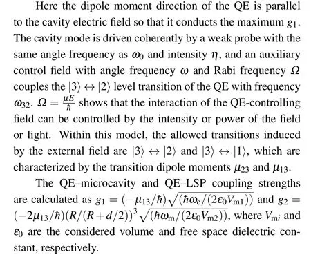
Figure 2(a)shows the output transmission as the expression|aout|/|ain| of the proposed scheme.The fixed parameters in this section are{κ1,κ2,γs,γ21,η}=0.07, 0.7, 0.086,0.002, 0.1 meV.The decay of the cavity is much smaller than the MNP with an order of around 10, and the weak probeηis smaller than the coupling strength of the system as well to satisfy the nonlinear effect at low optical intensity.The coupling strengths{g1,g2,J}=0.0206,1,2.9 meV of the interaction of the QE–cavity mode, the QE–MNP and the cavity–MNP are calculated referring to Ref.[26]but here providing the smaller dipole momentµ13=1e·nm.Due to the much smaller mode volume of the MNP than the microcavity, the coupling strengthg1≪g2is reasonable in spite of the stronger loss of the latter.As we can see, the output transmission of the analytical H-L equation and the numerical master equation are accordant with each other as seen in the experimental results of Refs.[14,41].At∆0=0, the narrow spectral peak representing the dark mode shows without the control field (Ω=0), while it disappears atΩ/=0.The detailed and quantitative description of the dark state is deduced using an interaction Hamilton later.
Figure 2(b) plots the normalized transmitted light power versus∆0without the assisted LSP mode (J=0,κ2= 0,g2= 0), which shows that the EIT effect makes the obvious conversion with the VF-EIT in the MNP-assisted cavity QED system.The system is composed of one microcavity and a three-level QE, and the parameters are chosen as{κ1,κ2,γs,γ21,η,g1,g2,J}=0.07,0,0.086,0.002,0.1,0.15,0,0 meV.WhenΩ= 0, the Rabi splittingThe narrow dip at∆0=0 shows that the system is under strong coupling in accordance withg>κ ≫γ.Conversely,when the control field is present,i.e.,Ω/=0,the narrow spectral peak at∆0=0 shows that the control field induces destruction interference between excited states of the QE.The probe light is essentially transmitted in the cavity and has little absorption by the medium.It is ascertained that the control field plays a critical role to achieve switching performance from the above two results.In view of Figs.2(a)and 2(b),there is no deviation between the peaks of the analytical and numerical results,but the strength of transmission shows differences due to the static approximation of the H-L equation.
Figure 2(c) depicts the VF-EIT with the wide range of strength of control fieldΩ=0–2 meV.This demonstrates the existence of the EIT effect and exhibits the switching response in our system fromΩ= 0 to a certain strength.The proposed model could provide an easier operation of light switching which provides continuous transmission by manipulating the detuning∆0and the intensity of the control fieldΩin the change from blue to red lines shown in Fig.2.Additionally,a pair of bright modes show in the off-resonant frequencies,and total coupling strength is enhanced.

Fig.3.The dependence of the EIT effect on detunings ∆0 and ∆p.(a)–(c)are the traditional cavity QED system,while(d)–(f)are the VF-EIT effects provided by the plasmon-assisted system,both including a 3LS QE for Ω =0 meV,1 meV,2 meV.Parameters are the same as above.
We consider the variation of output intensity if the probe light and control field are tuned off-resonance simultaneously in order to verify the dependence of additional conditions depicted in Fig.3.Here we discuss traditional and MNP-assisted systems as above with the variation of control fieldΩ=0–2 meV depicted in the first and second rows.The first panel is simplified as the cavity QED system with a three-level QE shown in Figs.3(a)–3(c).There are just two bright modes without the control field,while splitting once with the increasing control field.In the second panel,note that the intracavity dark mode splits into two modes which are enhanced by the increasing control field strength plotted in Figs.3(d)–3(f).However, the bright modes remain in the fixed detuning position∆0=0.16 meV in spite of the variedΩ.The second anticrossing is more obvious at the position of the bright mode.When the applied control field boosts,the frequency of the second Rabi splitting center is resonant∆p=0 meV.Thus,we can not only control the splitting position and strong coupling of the system by the control field but also the switch‘on/off’.Notably,the dark state apparently exists in our system without the need for the control field so the system shows a strong transmitted intensity.The bright modes remain almost unchanged in both results.Contrary to the EIT effect, the extra advantage of the proposed system is the shifting frequency of output light, showing that when the probe light is off-resonant with the cavity,the same transmitted efficiency can be exhibited by manipulating the intensity or power of the control field.This is useful for selective undistinguished frequencies of photons to enter and entangle in the entanglement swapping by means of tuning the strength of the coupling field.Referring to the results in Ref.[43],we have already given a general explanation of VF-EIT by adding an extra field so as to enrich the coupling process.This system of Guoet al.studied an N-type fourlevel QE and discussed the contribution of a microwave field added to couple the two ground states.This provides a helpful method to regulate the entry of photons and exclude the noise photons in the network node.The range of tuning frequency of probe light is ideally wide within the gap of bright modes as shown in Figs.3(e)and 3(f)(∆0=-0.5 meV to 0.5 meV).Notably,the time for the steady state in the plasmon-assisted cavity QED system is<50 ns which is three times smaller than that of the traditional cavity QED(150 ns)given in Ref.[44].
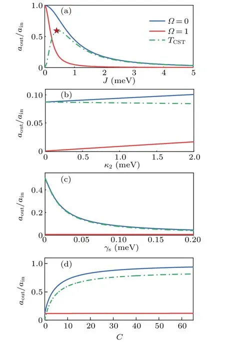
3.2.Switching contrast
The switching contrast is defnied by the difference of normalize transmission of the resonant photonTcst=At the resonance∆0=0, the contrast value of the LSP mode-assisted cavity QED system and conventional cavity QED has a significant discrepancy with 60%and<10% given in Figs.2(a) and 2(b).Further, the dependence of the switching contrast on the decoherence of the QE,cavity dissipation, imperfect mode matching and the LSP mode-QE cooperationC=(g2)2/(2κ2γs)is given in Figs.4(a)–4(d).Obviously,the mode-enhanced factor J is quite informational due to the existence of a maximum point in the switching contrast curve in the middle strengthJ ≈0.6 meV, which shows the critical dependence of a well-designed system.The FWHM corresponds to a range of coupling strengthJ(0.17–2.6 meV),which can be modulated by the spatial position and size of the MNP in the cavity.Parametersκ2andγsplay subtle roles in exploring the maxima or minima.Weak dependence of the decay rate of the LSP mode provides an advantage for eliminating cavity loss.Simultaneously, switching contrast diminishes exponentially with the increased dephasing rate of the excited state of the QE.The above discussion reveals that the moderate coupling strength of two fields and a small dephasing rate of the excited state of the QE are preferred for high switching contrast.In Fig.4(d), stable switching contrast (about 90%) is ensured onJ=0.6 meV even at the prior high cooperationCof Ref.[21].Conversely, due to the existence of the LSP mode, light is transmitted forΩ= 0 and absorbed forΩ/=0.So less dependence on the cooperativity is shown.Moreover, we also focus on the effect of QE–microcavity couplingg1in the lack of LSP mode-assisted system.For the bad cavityg1
3.3.Optical property of the QE
Next we discuss qualitatively the linear property of the medium to explain this VF-EIT effect.The real and imaginary parts of the susceptibility reflect the dispersive and absorbing nature.Without the extra control field, there is an interaction between the cavity field and QE level transition|1〉→|3〉.According to the Heisenberg–Langevin analytical method, the significant transmission peak appears at the resonant frequency due to rare absorption of the medium shown in Fig.5(a)(red line),which corresponds to the dark mode in Fig.5(a)(Ω=0),manifesting that the incident probe photon is nearly all trapped in the microcavity.At off-resonant frequencies shown in Fig.5(b),the absorption has two peaks and also corresponds to the gap between bright and dark modes in Fig.2 (Ω=1,2 meV).However, with the control field, the complete reversal happens at∆0=0 and exhibits the vanishing of the dark state at the fully resonant frequency.The real part of permittivity plotted in Fig.5(c) shows the anomalous dispersion from one to two contours corresponding to the central linewidth of the absorption profile.To make a contrast,the absorption and dispersion of a one QE–one cavity system are also depicted in Figs.5(a)–5(d) (blue line).Without the control field,the output transmission exhibits the strong peaks of Rabi splitting which illustrates the non-existent dark state,as shown in Fig.5(a)(blue line).Due to the manipulation of the control field, the strong absorption at∆0/=0 corresponds to the weak bright mode,while the stronger EIT peak is shown at a resonant frequency in Figs.5(b) (blue line) showing the occurrence of the dark state.The reflective index of the LSP mode-assisted system is four times as large as that of the traditional cavity QED system shown in Figs.5(c)and 5(d)showing stronger manipulation of the structure.
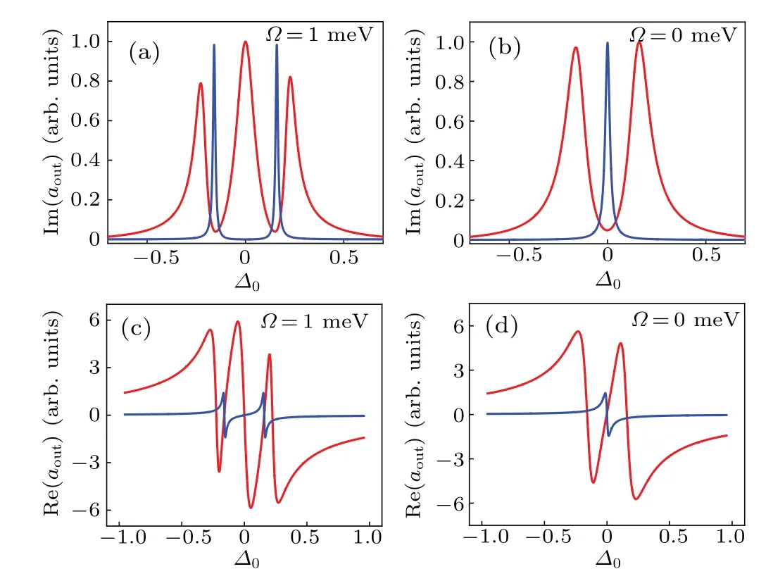
Fig.5.The absorption and dispersion of the medium of Ω =1 meV(a)and(c),and Ω =0(b)and(d)for VF-EIT of the MNP-assisted cavity QED system (red line) and EIT system (blue line).Other parameters are equal to the MNP-assisted and traditional cavity QED system as in the above discussions,respectively.
3.4.Quantum interference explanation
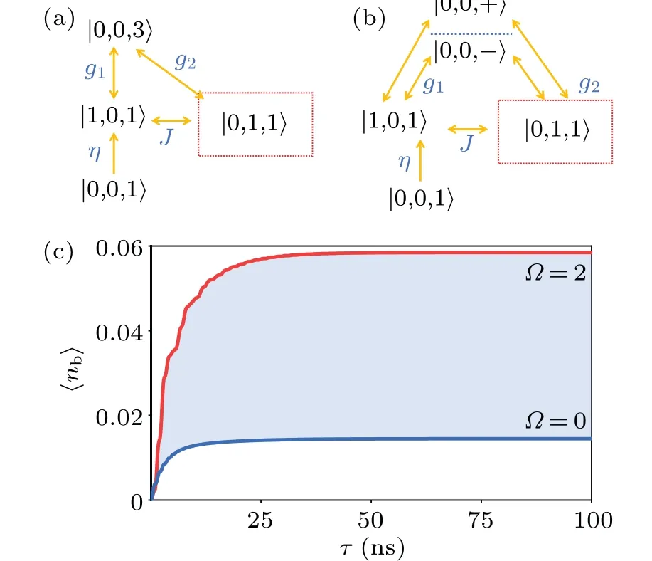
Fig.6.Energy-level and transition pathway diagram of the coupled cavity–QE(a)without and(b)with the control field in the LSP modeassisted system.The quantum interference effect between different transition pathways for the transition |3〉↔|2〉 of the QE due to the presence of a control field leads to the counterintuitive EIT effect.The Dirac operator is a direct product of the Fork state of the cavity photon and the population of the QE.Here one Fork state is considered. g1 and g2 is the coupling between the transition of |3〉↔|1〉 and the microcavity,and the LSP mode,respectively. J refers to the mode-enhanced factor between the microcavity and LSP mode.(c) Population evolution of mean photon number of LSP mode for VF-EIT versus different strength of control field Ω =0 meV and Ω =2 meV.
Considering the Hamilton term of all interactions and the pump of the control field, the density matrix of the proposed system can be given as
The eigenvalues of the matrix reflect the states of the scheme.
Next, in the proposed MNP-assisted system, the middle EIT peak represents the intracavity dark state when the control field is absent.The quantum explanation is destructive interference due to mode interaction between the extra LSP mode and cavity field which plays the main role.The ground state basis of the coupled system|0,0,1〉 experiences the probe lightηof the cavity and yields|1,0,1〉.Two coherent transition pathways are plotted in Fig.6(a).One is coherent coupling|1,0,1〉→|0,0,3〉withg1,while the other is two steps|1,0,1〉→|0,1,1〉→|0,0,3〉 with coupling strengthJandg2.The systematic eigenstates can be written as
During this process,the population on middle|1,0,1〉is suppressed, steering the system to a dark state as seen with two fields in Ref.[42].Therefore, there is no medium absorption and no effects on the cavity photons.Notably,variation ofΩhas little effect on the frequency range of bright modes shown in Figs.3(b)and 3(c).The broad frequency of bright modes is located on the off-resonant frequency at∆p=±0.5 meV.
In the case of applying the control field,the excited state of the QE degenerates to a dressed state, and the whole systematic states include|1,0,1〉,|0,1,1〉,|0,0,±〉as shown in Fig.6(b).The destructive interference between two coherent excitation paths of the QE(|2〉±|3〉)seen in the conditional EIT effect is induced due to the same strength and opposite phase[43]at the frequency of probe resonance.However, the third coherent pathway is formed due to mode-enhanced factor J between|1,0,1〉 and|0,1,1〉.Thus, the formation of destructive interference and the dark state vanishes.Additionally,variation ofΩhas proportional manipulation on Rabi splitting of dark modes.As shown in Fig.2,a single EIT peak splits into two peaks near resonance frequency and resonant frequency can be given as four eigenvalues and written asλ2=From the above expression,the decisive factor to prepare the dark state is whether or notJ2Ω2=0.Hence,reliable evidence to generate a dark state in the LSP mode-assisted system is again given without the control field.
In Fig.6(c),it can be seen that the transient evolution of the population of the LSP cavity reflects the distribution of systematic states.For the dark stateΨdatΩ=0,the|0,1,1〉state is destructive interference and the number of LSP cavity photons is substantially reduced.Contrarily,the population shows an increasing trend atΩ/= 0 because of the vanished dark state and all contributions of the four eigenstates of the system.After destructive interference occurs,the electronic state is trapped in the excited state of the QE.This corresponds to the inversion of the dark state to manipulate the switch’on/off’state.
4.Conclusion
In conclusion, we have achieved the high and stable switching contrast and variable frequency of photon output from the one-sided LSP mode-assisted cavity QED system,even with smallJand high cooperativityCby tuning the intensity of the control field.A full analytical solution is given to describe transmission spectra and eigenstates for the evolution of the system on the basis of the Heisenberg–Langevin equation and input–output relation the solution of which is universal for the interaction of three modes on cavity QED systems.The quantum interference is presented to describe the evolution of systematic states by the absence or presence of the control field.Due to the destructive interference,a certain systematic state vanishes that renders one of the microcavity or LSP photons trapped without the control field.At macro scales,the electric susceptibility of the medium is significantly different between VF-EIT and EIT effects.In long-distance entanglement swapping,selecting a certain frequency of photons for Bell-state measurement(BSM)is a critical step to conduct the entangled photons.As the network nodes via the photonic link,the LSP mode-assisted system is embedded in the quantum circuit to help select a certain frequency of input photon.
Here we propose several experimental realizations to achieve the LSP mode-assisted cavity QED to manipulate optical switching.Jauffredet al.optically trapped an individual airborne gold nanoparticle using a single infrared laser beam.[45]By constructing three chambers to trap a single particle easily, the measurement time is about 0.04 s, which is much longer than the switching process(the order of ns).TheΛ-type artificial QE can also be trapped by applying another laser with visible wavelength.Then ideally, through infinite approaching MNP and QE by modulating two lasers,the transient sub-nanometer distance between the MNP surface and the QE can be achieved.An order of GHz microwave drives the magnetic-dipole transition between two hyperfine ground states of the QE to form aΛ-type QE.Finally, by turning on/off the controlling field applying to the optical medium state-excited state, transmission of the probe light can be detected in the same direction in the one-sided system.
However,the accurate control of the position of 10–20 nm between the QE and MNP in the air and the total resolution of the two particles is challenging.Hence,providing the fixed QE and movable MNP through the optical tip makes the theoretical system possible.Firstly,the QE can be fixed on the surface of molecules or spheres which cannot respond to the characteristics of interaction with light by a self-assembly technique.Then, the position of the MNP is controlled by an AFM tip with the precision of a few dozen nanometers.[46,47]The cavity could be provided by the waveguide.The whole experiment can be achieved with the on-chip device.
Acknowledgements
The authors acknowledge support from the National Natural Science Foundation of China (Grant Nos.62075004 and 11804018)and the Beijing Natural Science Foundation(Grant No.4212051).
猜你喜欢
小主人报(2022年7期)2022-08-16
作文小学中年级(2021年12期)2022-01-21
小主人报(2022年2期)2022-01-19
作文小学高年级(2021年10期)2021-11-08
作文小学中年级(2021年9期)2021-10-20
数学小灵通(1-2年级)(2020年11期)2020-12-28
作文小学高年级(2020年2期)2020-04-18
海峡姐妹(2020年1期)2020-03-03
作文大王·低年级(2019年11期)2019-12-02
Chinese Physics B(2019年7期)2019-08-06

- Chinese Physics B的其它文章
- Optimal zero-crossing group selection method of the absolute gravimeter based on improved auto-regressive moving average model
- Deterministic remote preparation of multi-qubit equatorial states through dissipative channels
- Direct measurement of nonlocal quantum states without approximation
- Fast and perfect state transfer in superconducting circuit with tunable coupler
- A discrete Boltzmann model with symmetric velocity discretization for compressible flow
- Dynamic modelling and chaos control for a thin plate oscillator using Bubnov–Galerkin integral method