
Numerical Simulation of Particle/Matrix Interface Failure in Composite Propellant
2012-07-25 06:22CHANGWujun常武军JUYutao鞠玉涛HANBo韩波HUShaoqing胡少青WANGZhengshi王政时
Defence Technology 2012年3期
CHANG Wu-jun(常武军),JU Yu-tao(鞠玉涛),HAN Bo(韩波),HU Shao-qing(胡少青),WANG Zheng-shi(王政时)
(School of Mechanical Engineering,Nanjing University of Science and Technology,Nanjing 210094,Jiangsu,China)
Introduction
The composite propellant is a kind of energetic material with very high volume fraction of particles in binder matrix,and therefore its macroscopic mechanical behavior strongly depends on its microstructure.In the microscale,it is a heterogeneous mechanical mixture,and has obvious interfaces between components.Thus,its mechanical properties depend upon the viscoelastic properties of the polymer binder,particle volume fraction and particle/matrix interface cohesive properties greatly.Under external loads,the microstructure of propellant will take place a series of changes,such as microcracks propagation,voids growth and localized stress concentration.The microstructure of cohesive interface will be damaged,leading to particle/matrix interfacial debonding,namely dewetting,thereby affecting the macroscopic mechanical properties.However,due to the complexity of micromechanics behavior and the limitations of experiment equipment and test method,it is difficult to quantitatively analyze the microstructure failure and damage evolution laws experimentally.Therefore,the numerical simulation based on microstructure model has a great significance.However,it is confronted with some difficulties,such as the modeling of microstructure,the mechanical model and constitutive parameters of components and the simulation scheme.The complexity of numerical simulation is associated with the coupled of competing physical processes in large scale:finite deformation of quasi-incompressible polymeric matrix,large stiffness mismatch between energetic particles and the matrix,particle debonding,matrix tearing,void growth and coalescence,particles interaction[1],etc.
In order to illustrate the composite propellant damage characteristics and failure process,LIU[2]and YUAN[3]analyzed the micro-mechanical failure mechanisms of composite propellant.Zhong[4],Matous[1,5]and Inglis’s[6]studied the cohesive theory and particles interface debonding damage evolution.HAN[7]used a cohesive model to simulate the crack propagation process.But,the microscopic damage evolution law and the essential reasons on the development of macroscopic behavior have not yet been clear,thus,we need to further reveal the correlation between microstructure and macroscopic mechanical properties.
In this paper,the particle/matrix interface damage is simulated using cohesive elements;the mechanical response is governed by using the bilinear constitutive relation.The influences of the interface cohesive properties on the mechanical characteristics are analyzed.The damage evolution of the composite propellant subjected to uniaxial tension load is simulated in finite deformation.The damage nucleation,propagation mechanism and non-uniform distribution of microstructural stress-strain field are obtained.It provides a theoretical basis for damage and failure assessment methods based on the cohesive zone model.
1 Analysisfor Interface Cohesive Failure
The particle/matrix interface of composite propellant is formed in complex chemical and physical processes while the solidfication and cross-linking reactions between binder matrix and particles.The interface chemical bond forces at chemical cross-linking points and the interface physical adsorption forces at physical cross-linking points exist in two-phase interface.The composite propellant has very large specific surface area,i.e.the interface area per unit volume,because of high volume fraction of energetic particles.Therefore,the mechanical behavior of particle/matrix interface significantly influences the macroscopic behavior greatly.
The experimental studies[8]show that the microcracks appear in tension process at some large particles,with opening normal to the applied loading direction.As the deformation continues,the original and new cracks propagate along interfaces,making the large amount of particles dewetting.The bridge stress in zones of large particles results in the stress concentration and more serious debonding.The debonding leads to a decline of macroscopic elastic modulus,the nonlinear stress-strain curves and also the volume expansion,so that Poisson's ratio gradually decreases.It ultimately makes the propellant materials fracture.Fig.1 presents the dewetting morphology before the fracture of propellant specimen.It can be seen that the volume fraction of solid particles is higher and the majority of large particles are fully debonding.Therefore,the interface debonding in the microstructure is one of the principal forms of damage and failure of these materials.
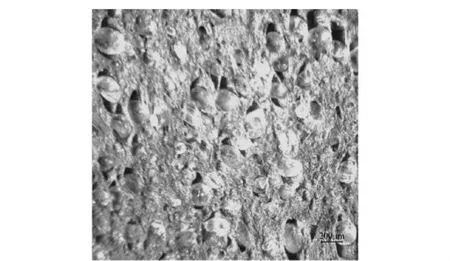
Fig.1 Propellant microscopic morphology at strain of 42%(×50)
2 Microstructure and Finite Element Simulation
2.1 Computational Model
To achieve high energy content,the composite propellant is typically characterized by a wide distribution of particle sizes.Larger particles are 100-300 μm in diameter,while the small particles have a mean diameter of about 20 μm.As mentioned earlier,the interface damage starts from the larger particles.The small particles serve merely to stiffen the binder matrix.Therefore,the volume fraction of ammonium perchlorate(AP)particles can be assumed as 64%,with large particles of 34%.The remaining small particles of 30%are combined with binder and other constituents to create a composite matrix.Thus,an ideal solid propellant can be considered as the composition of AP particles randomly embedded in a matrix.The particulate composite system can be modeled as three models,i.e.2D cubic cell model,four-particles model and random particles stacking model generated by the random algorithm[9],as shown in Fig.2.To simulate the mechanical behavior under uniaxial tension with constant speed,the boundary should remain straight deformation[2-3,10].Namely,σx= ∫σxdy=0.The microstructure is calculated under plane strain assumption,by means of loading displacement.
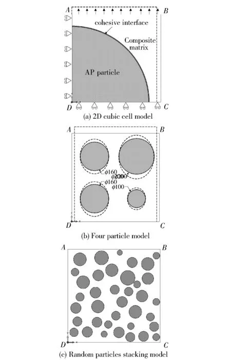
Fig.2 FEM models of propellant
2.2 Material Constitutive Model
AP particles can be approximately considered as rigid,because of its huge elastic modulus compared with polymer binder,while the small particles and binder can be considered as uniform hyperelastic composite matrix and its nearly incompressible mechanical behavior can be described by using Neo-Hookean constitutive model.The strain energy function can be written as
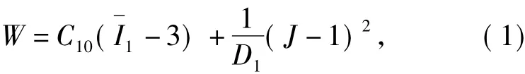
whereWis the strain energy per unit of reference volume,C10andD1are the material parameters,is the first deviatory strain invariant defined as,the deviatory stretches,Jis the total volume ratio,The initial shear modulusμ0and bulk modulusK0are
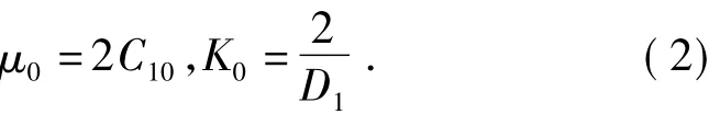
To describe the mechanical behavior of the nearly incompressible matrix under plane strain assumption,slight compressibility is introduced.The ratio ofK0/μ0can be also expressed in terms of Poisson's ratio,since
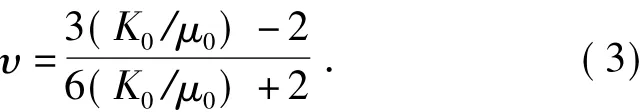
Other parameters of composite matrix are obtained from Eq.(2)and(3),as shown in Tab.1,andK0/μ0=555.2,D1=0.001 461.
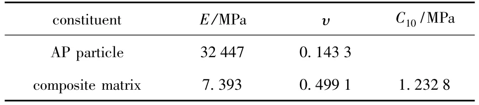
Tab.1 Mechanical properties of individual constituents[1]
2.3 Mechanical Model of Interface
To exactly describe the interface mechanical behavior and damage evolution,the cohesive zone model is used to simulate the nucleation and propagation of interface damage.A phenomenological relation between normal or shearing stress and opening or sliding displacement is used to define the particle/matrix constitutive behavior.Moreover,the bilinear constitutive model[2,5-6,11]is widely used because of relatively simple expression and can be written as

whereTmaxdenotes the interface strength,Kis the interface modulus,is the softening modulus,δ0andδfare the critical opening displacement of damage initiation and interfacial failure,respectively.
黄永超[18]发明了一种荧光微球示踪剂。该示踪剂以丙烯酰胺和N-苯并噻唑马来亚酰胺为主要原料,采用反相乳液聚合法制成。为纳米级颗粒,具有分散性好、抗温抗盐能力强、用量少、检测灵敏度高和荧光强度高等优点。
The determination of interface parameters is the key in numerical calculation,which are predicted by references and experience at present.The interface strength represents initiation of damage,and has a great influence on the numerical results.Tan[12]considered that the interface strength differed from the macroscopic strength a litter for the materials with high particles volume fraction.Thus,the interface strength can be taken as 0.5-1.0 MPa,according to the performance of HTPB propellant at normal temperature.The interface modulus has little effect on the results,but it affects the convergence greatly.The small initial stiffness of interface will cause an extra deformation,while too large one results in the parasitic oscillation of interface stress[11].Due to the large stiffness mismatch between particles and matrix,the interface modulus should be determined by repeat numerical attempts.TakeK=500 MPa/mm.The opening displacement of failure is related to fracture energy,thusGc=2-8 J/m2.
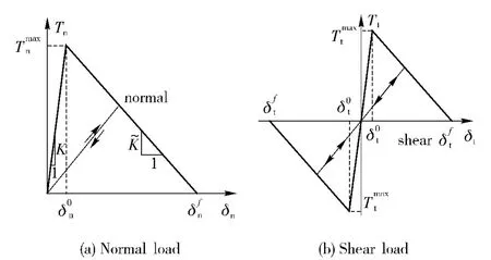
Fig.3 Bilinear constitution
The deformation in the bilinear model interface before damage is assumed as linear elastic deformation.The damage process begins when the interface bears a critical load as shown in Fig.3.Thus,the elastic behavior can be written as
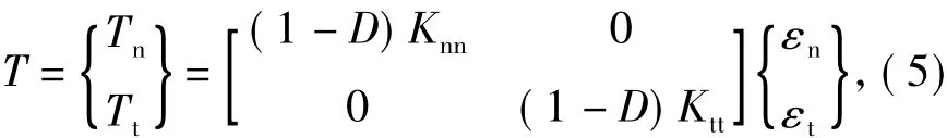
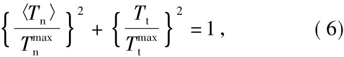
For the arc interface of AP spherical particles,the states of stress-strain are more complex.In the mixed mode of shearing and normal stresses together,The damage may initially occur when the stress is less than the interface strength.Therefore,a quadratic stress criterion is used to predict the damage initiation.Its expression can be written as
2.4 Meshing Method
Under the planar strain assumption,the hybrid element has to be chosen to simulate the mechanical response of incompressible hyperelastic matrix.When the large deformation occurs in the matrix,the penetration across particles/matrix often happens.Thus,the general contact algorithm is used by defining friction penalty function.
Embed a layer of cohesive element with zero thickness in the interface to analog the mechanical response of particle/matrix interface.The sweep meshing technology has to be used to partition the cohesive elements.In addition,the appropriate viscosity can be introduced to cohesive elements,and a smaller load step can be set to ensure a perfect convergence.
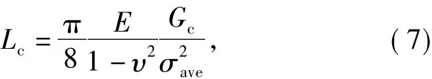
whereσaveandGcare the average interface strengths and fracture energy,respectively.The minimum size of cohesive zone can be obtained by substituting the material properties of composite matrix and interface.
3 Results and Analyses
3.1 Effects of Interface Properties on Mechanical Behavior
The macroscopic stress-strain curves of single particle model at different interface strength are shown in Fig.4.The elastic deformation and stress increase linearly in stageⅠ.The overall modulus is obviously larger than that of the pure matrix,and the particles have great enhancement effect.The stress-strain curves coincide essentially before reaching the critical strength.In stageⅡ,when reaching the critical strength,the stress appears to soften.The interface damage evolution happens sharply,and the load capacity drops rapidly.The maximum stress firstly occurs near the polar region of particles,and leads to the damage initiation.With the development of crack propagation along the particle/matrix interface,the macroscopic mechanical behavior changes gradually.Then,in stageⅢ,the stress-strain curves rise gradually because of the large deformation of composite matrix,and the complete failures are similar.
With the increase of interface strength,the propellant deforms elastically to greater tensile strength before the interface damage begins,and the decline of stress is steeper.Thus,the interface damage evolution and material failure process takes place quickly,because the improvement of interface strength makes the higher stress threshold and gathers more strain energy before the material damage.Therefore,more energy will release rapidly once the failure happens.
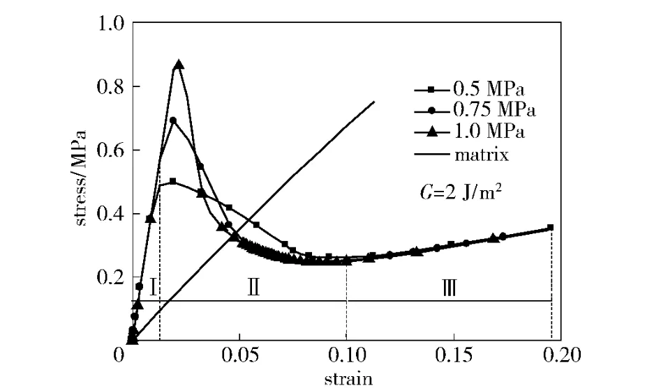
Fig.4 Stress-strain curve at different interface strengthes
Figure 5 shows the distribution of Mises and axial stresses at the interfacial strength of 1 MPa and strain of 10%,when the interface de-bonds to 45°.The stress distribution of composite propellant is highly heterogeneous,and the maximum value occurs near the tip of cohesive zone,prior to the crack.The particles can hinder the matrix deformation,so the compressive stress occurs in the equatorial plane of particle.The interface damage fraction,i.e.the ratio of damage interface length to total interface length,can be considered as a criterion to judge the damage extent.The damage evolution law is shown in Fig.6.It is clear that the damaged interface has reached to 80%or more,when the crack tip is in the position of 45°,so the interface has a longer cohesive zone length.

Fig.5 Stress contours of unit cell at strain of 10%
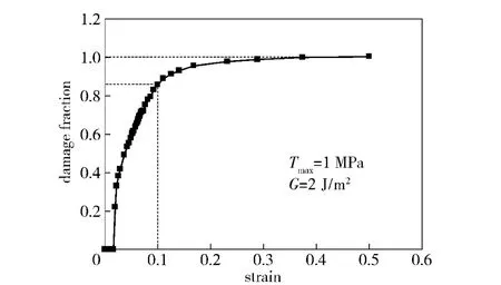
Fig.6 Particle interface damage evolution law
Figure 7 illustrates the influence of interface fracture energy on the macroscopic stress-strain law in the same critical strength.There are only little influence on the linear stage and complete failure stage.With the increase of fracture energy increases,the macroscopic tensile strength improves also,and the interface damage evolution will slow down.After the complete interface damage,the interface does not bear the load and the matrix becomes the only subject to bear the load.It can be seen that,for larger fracture energy,the material can achieve a greater elongation at the moment of failure.The fracture energy is a measure of energy dissipation in the failure process.The improvement of interface toughness will result in a larger cohesive zone,thus the interface can bear the load for longer time before the failure occurrence.
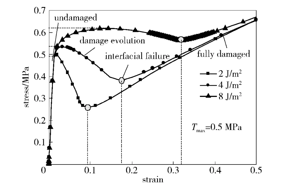
Fig.7 Stress-strain curve for different fracture energies
3.2 Multi-scale Damage Characteristics and Failure Mechanism
It can be known from the damage evolution of four-particles model,as shown in Fig.8 and 9,that the macroscopic stress-strain curve becomes more complex,and the damage evolution has the critical points corresponding to the damage initiation and complete failure of large and small particles,respectively.The damage starts around the larger particles as observed in experiments,and is closely related to the particle interaction and sizes.The stress concentration appears at the stress bridging zone and cohesive tip of large particles,likely leading to the matrix tearing and void gathering,then the small particles will gradually produce larger stress after the unloading of large particles.Therefore,the micromechanical failure process of composite propellant can be divided into four stages,as shown in Fig.9.The stage I is an overall elastic deformation stage.In the stage II,the damage evolution of particle/matrix interface happens,and the stress decrease gradually with the increasing strain.This is the microscopic reasons of strain softening in propellants.The large deformation of matrix occurs in the stage III.The stress increases along with the strain,because the matrix is the only subject to bear the load after complete interface damage,i.e.the matrix tensile deformation is the main reason for the strain enhancement of propellant.Then,the matrix will tear and fracture in the stage IV,with the particle debonding and the large deformation of matrix,the fibrils of binder matrix and microvoids surrounding the particles form and grow,then,the fibrils rupture and micro-voids coalesce,finally leading to the fracture of composite propellant.
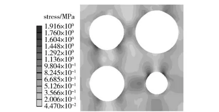
Fig.8 Von Mises stress in matrix at strain of 7%
3.3 Simulation on Microscopic Damage Evolution

Fig.9 Stress-strain curve of four-particle model
In fact,the high volume fractions in real composite propellant are achieved by using a wide distribution of particle sizes.The Mises stress contour for random packing propellant is shown in Fig.10.The damage starts mainly around the large particles and local particle-intensive zone,and accelerates the local damage process.The direction of interface opening displacement coincides with the loading direction.Fig.11 shows the macroscopic stress-strain law based on microstructure model.The particle/matrix interface damage is still the key factor to the propellant mechanical properties.The dewetting leads to the nonlinear stressstrain and a stress platform,also makes the macroscopic modulus decrease.The volume expansion happens in propellant,so Poisson's ratio will decrease.
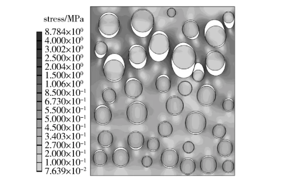
Fig.10 Mises stress distribution at tension strain of 8%
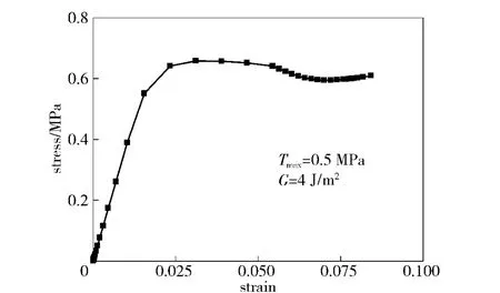
Fig.11 Stress-strain curve of random particle packing model
However,there is difference between the simulation and experiment,and a real microstructure model,exact interface parameters are needed and the fracture behavior of matrix has to be considered.
4 Conclusions
In this paper,a microstructure model under uniaxial tension to simulate the damage evolution of composite propellant subjected to finite deformation is established.The damage nucleation,propagation mechanisms and non-uniform distribution of microstructural stress-strain fields,particularly,the effect of interface properties and particle sizes on the mechanical response,are obtained.
1)The finite element simulation method based on the microstructure model can effectively predict the trend of macroscopic mechanical behavior and particle/matrix damage evolution process.It can be used for the damage simulation and failure assessment.The micromechanical failure process of composite propellant can be divided into four stages,i.e.elastic deformation,damage evolution of particle/matrix interface,large deformation of matrix and matrix tearing and fracture.
2)The damage starts around the larger particles and is closely related to the particle interaction and particle sizes.The stress concentration appears at the stress bridging zone and cohesive zone tip of large particles.The dewetting significantly leads to a decline of macroscopic elastic modulus,the nonlinear stressstrain curves and also the damage of propellant.
3)The improvement of interface strength and fracture energy can achieve a greater tensile strength and elongation of composite propellant.
[1]Matous K,Geubelle P H.Finite element formulation for modeling particle debonding in reinforced elastomers subjected to finite deformations[J].Computer Methods in Applied Mechanics and Engineering,2006,196:620 -633.
[2]LIU Zhu-qing,LI Gao-chun,XING Yao-guo,et al.Numerical simulation and SEM study on the microstructural damage of composite solid propellants[J].Journal of Propulsion Technology,2011,32(3):412-416.(in Chinese)
[3]YUAN Song,TANG Wei-hong,LI Gao-chun.Analysis on micro-mechanical failure mechanisms of composite propellant[J].Journal of Solid Rocket Technology,2006,29(1):48-51.(in Chinese)
[4]Zhong A X,Knauss W G.Analysis of interfacial failure in particle-filled elastomers[J].Journal of Engineering Materials and Technology,1997,119:198-204.
[5]Matous K,Inglis H M,Gu X,et al.Multiscale modeling of solid propellants:from particle packing to failure[J].Composites Science and Technology,2007,67:1694 -1708.
[6]Inglis H M,Geubelle P H,Matous K.Cohesive modeling of dewetting in particulate composites:micromechanics vs.multiscale finite element analysis[J].Mechanics of Materials,2007,39:580 -595.
[7]HAN Bo,JU Yu-tao,XU Jin-sheng,et al.Numerical simulation of crack propagation in solid propellant based on cohesive zone model[J].Journal of Ballistics,2012,24(1):63-68.(in Chinese)
[8]CHANG Wu-jun,JU Yu-tao,WANG Peng-bo.Research on correlation between dewetting and mechanical property of HTPB propellant[J].Acta Armamentarii,2012,33(3):261-266.(in Chinese)
[9]Segurado J,Llorca J.A numerical approximation to the elastic properties of sphere-reinforced composites[J].Journal of the Mechanics and Physics of Solids,2002,50:2107-2121.
[10]Ghassemieh E.Micro-mechanical analysis of bonding failure in a particle-filled composite[J].Composites Science and Technology,2002,62:67-82.
[11]Segurado J,LLorca J.A computational micromechanics study of the effect of interface decohesion on the mechanical behavior of composites[J].Acta Materialia,2005,53:4931-4942.
[12]Tan H,Liu C,Huang Y,et al.The cohesive law for the particle/matrix interfaces in high explosives[J].Journal of the Mechanics and Physics of Solids,2005,53:1892-1917.
猜你喜欢
化工与医药工程(2022年3期)2022-08-08
石油地质与工程(2022年4期)2022-08-06
石油化工应用(2022年3期)2022-04-20
小作家报·教研博览(2022年11期)2022-04-02
陶瓷学报(2021年5期)2021-11-22
陶瓷学报(2021年5期)2021-11-22
化工管理(2021年23期)2021-08-25
西安石油大学学报(自然科学版)(2021年1期)2021-01-27
石油化工高等学校学报(2020年2期)2020-05-08
石油化工高等学校学报(2020年1期)2020-03-05

- Defence Technology的其它文章
- An Investigation on a Tin Fixed Abrasive Polishing Pad with Phyllotactic Pattern for Polishing Wafer
- An Approximate Calculation Method for Lateral Trajectory Correction
- Lift Enhancement and Oscillatory Suppression of Vortex-induced Vibration in Shear Flow by Loentz Force
- A Study on Criteria for Barrel Lifetime
- Research on Microcrack Extension Mechanism of SiCp/Al in the Machining Process
- Molecular Dynamic Simulation for HMX/NTO Supramolecular Explosive