
Effectiveness of a Passive-active Vibration Isolation System with Actuator Constraints
2014-03-01 01:47SUNLinglingSUNWeiSONGKongjieandHANSENColin
SUN Lingling , SUN Wei SONG Kongjie and HANSEN Colin H
1 Key Laboratory of High-efficiency and Clean Mechanical Manufacture, Shandong University, Jinan 250061, China
2 School of Mechanical Engineering, University of Adelaide, South Australia 5005, Australia
1 Introduction
The reduction of vibration transmission from a machine to its supporting structure has been the subject of considerable research effort over many decades[1–5], and has included the investigation of active, semi-active and passive control[6–8].
For active isolation systems, feedforward control is invariably preferred over a feedback system whenever a suitable reference signal is available. Fortunately, the disturbance being controlled in many cases is periodic, and this commonly occurs where the primary source comprises rotating machinery. The feedforward control algorithm in the frequency domain was first used for the problem of four active isolators between a vertically vibrating rigid body and an edge-clamped flexible plate[9]. The isolation efficiency and predicted magnitude of the control forces were investigated using the finite element method.Analyses were then undertaken for multiple excitation forces and various types of supporting structures[6–7,10–12].
Among the control strategies proposed for the active isolation systems, minimization of overall energy in the supporting structure produces much better results than those obtained using minimization of squared acceleration(velocity) or force at a single point[13–14]. For this reason,JENKINS, et al[9], studied two vibration isolation systems using the summation of squared acceleration from multiple measurement points to minimize the power output and achieved about 20–30 dB attenuation at the resonance frequencies of the support structure. SOMMERFELDT[14]investigated a multi-channel controller to minimize the square error signals from accelerometers attached at each corner of the plate. The results showed that up to 45 dB attenuation was locally achieved by the active controllers with good stability. PAN, et al[10], considered the total power transmitted through the connection points to the supporting structure as the cost function, on the basis that the minimization of vibratory power would ensure a significant reduction in vibration levels throughout the structure. GARDONIO, et al[11], analyzed the power transmission from a vibrating rigid body into an infinite or finite plate through two active mounts. Cost functions for minimizing the out-of-plane power and the weighted sum of the out-of-plane squared forces were proposed and the results were compared to those obtained by the control strategy of minimization of total power transmission. As an extension of the work of PAN, et al[10], a theoretical and experimental analysis of a six-axis vibration source actively isolated from a finite cylindrical shell was presented[15], in which an impedance head was developed to measure the force and acceleration in each direction, so that the power transmission could be minimized.
In the prediction of active-passive isolation performance,several issues have been ignored in previous work. For a real isolation system, the machine supported on isolators has multiple degrees of freedom, and the primary forces and moments excite resonances in the elastic mounts as well as the supporting structure. The resulting vibration components contribute to the total power flow, while each possible excited resonance could have an adverse effect on the active isolation performance. However issues such as the physical mechanisms associated with single vibration component control and the effects of waves in elastic mounts have not been fully addressed. To understand and improve these effects on the control performance of an active isolation system, a detailed theoretical analysis of such systems must be developed.
Another key issue when considering the use of an active control system is how powerful the active actuator must be.This issue largely determines whether the potential performance can be achieved. In spite of the design guideline suggested by JENKINS, et al[9]that the combined active/passive isolation mounts could reduce the total power transmission without leading to control force requirements which are in excess of the primary force generated, in previous work, whether the actuator capability would limit the realization of theoretically predicted active performance has not been addressed. The commonly used control strategies are predicted with cost functions containing no control force constraint. The use of control effort constraint was proposed years ago and its effect on the performance of active noise control systems was emphasized[16–18], but active isolation system with actuator constraints or global performance indexes has not been investigated.
This paper extends early work on the development of realizable control strategies for actively isolating the transmission of vibration from a machine into a flexible plate. The commonly used cost functions are modified to minimize the performance index subject to control force constraints. A theoretical model of a multi-degree-offreedom active-passive isolation system is developed and the transfer matrix method is used to analyze the input-output response of the coupled isolation system. The passive resilient mount and the flexible supporting plate are modeled as distributed parameter systems. Each power transmission component induced by the vertical and transverse forces, and the rotational moments and then transmitted through the isolators into the supporting plate is taken into account. The overall behaviour of the proposed control strategies is illustrated by simulation. The theoretical results are then compared with those obtained using unconstrained control strategies.
2 Theoretical Model
In this section, a theoretical analysis of the vibration transmission from a rigid body into a flexible supporting structure through the active-passive mounts is developed by using the transfer matrix method. As shown in Fig. 1, the supporting structure is modelled as a simply supported rectangular plate, on which the vibrating rigid body is supported via isolators. Generally, the rigid body is free to vibrate in six degrees of freedom. As the drilling degree of freedom of the plate is suppressed, the twisting moment about the z axis does not transmit any energy into bending waves in the support structure and so is not considered here.Considering the same solution applies to problems in y-z plane and z-x plane, only the vibration of the system in the z-x plane is analyzed. The isolators consist of active actuators in parallel with flexible passive mounts, in which the passive mounts are used to provide isolation in all directions, while active actuators act vertically on the support plate and react on the rigid body.

Fig. 1. Vibrating rigid body isolated from a flexible plate using passive-active mounts
As assumed in previous work, the system under control is linear and the disturbances are deterministic. The deterministic disturbances are considered as being decomposed into their constituent frequency components if the disturbance is periodic. The effects of feedforward control on each of these discrete frequency components can then be considered independently and superposition applies.As for random disturbances, practical control systems will be implemented using digital filters and the control algorithms formulated in time domain.
The primary excitation applied at the rigid body is not simply a vertical force, but a combination of vertical and transverse forces as well as a rotational moment, as shown in Fig. 1.
2.1 System equation of motion
The equation of the motion for the overall system is synthesized from equations of motion for each of the three subsystems: the rigid body, the mounts and the flexible support plate.
It is assumed that the excitation forces and moment act on the center of gravity of the rigid body, and are denoted asas shown in Fig. 1. The corresponding velocity responses at the gravity center of the rigid body are given byThe output force and velocity vectors of the rigid body at the n connection points with the isolators are denoted Faand Varespectively, where each element of the matrices Faand Varepresents forces, moments and generalized velocities at the connection point. All quantities are in the complex form with the time dependent function of exp(jt) omitted for brevity.
The motion of the rigid body can be expressed in mobility matrix form
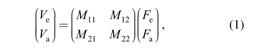
where Μij(i , j=1,2)are mobility sub-matrices. Μ11=J−1/j, J is the diagonal matrix of inertia relative to the center of gravity.TFand Tvare the matrices used to correlate the force and velocity vectors Faand Fewith Vaand Veby considering the rigid body constraint .

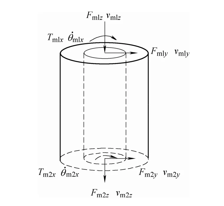
Fig. 2. Theoretical model for a cylindrical isolator
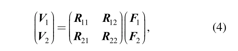
The transfer matrix equation describing the motion of the resilient mount can be derived using modal analysis method[19]:

When an active actuator is connected in parallel with the passive mount, the actuator exerts a vertical control force on the rigid body and the support point on the panel simultaneously. Assuming that the actuators are acting at the same locations as the passive isolators, Eq. (2) becomes

where Fmurepresents the control forces generated by the mth actuator acting on the support plate, anduT is the transformation matrix that relates the control forces to the relative vertical velocity components in Vm1, Vm2.
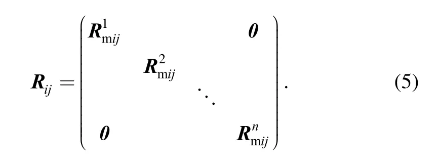
For an isolation subsystem with n active-passive isolators connected in parallel with each other, the equation of motion of the mount subsystem can be obtained by synthesizing matrix equations of n active-passive isolator pairs:
The supporting structure is modeled as a simply supported rectangular plate. At each connection point, the supporting plate is driven by concentrated forces (in the y and z directions) and bending moment (around the x axis).It is assumed that in-plane forces act in the middle of the plate cross-section. The in-plane waves induced by the transverse forces, out-of-plane flexural waves induced by the vertical force and bending moment are taken into account. By using wave equations[20], the corresponding driving point mobility and transfer mobility at each point of the supporting structure can be derived. Considering the out-of-plane motion and the rotations about the x axis as a couple and superimposing the contributions from the connection points, the supporting structure equation of motion can be described by the following mobility matrix form:
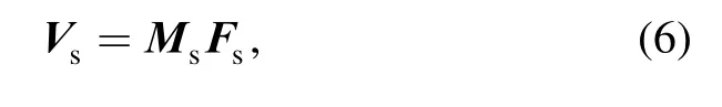
where Fsand Vsare driving force and moment vector, and relative velocity response vector respectively, at the connection points of the supporting plate. The mobility matrix Mscan be expressed by the force and moment mobilities at the connection points of the supporting plate[21].
2.2 Optimal control forces
The subsystem Eqs. (1), (4) and (6) are coupled by imposing conditions for continuity of forces and displacements at their interfaces, that is, at the isolators’attachment to the rigid body and supporting structure.Synthesizing these equations, the output force and velocity response vectors Fsand Vscan be obtained in terms of the excitation force vector Feand control force vector u as follows:

where
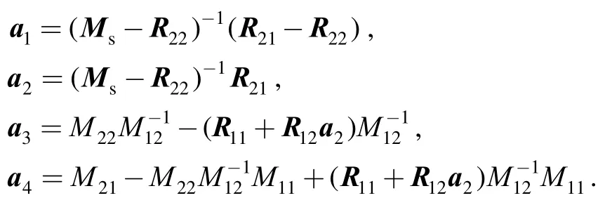
The control force vector u consists of each control force output of n actuators.
The total power transmitted into the supporting structure Psis given by
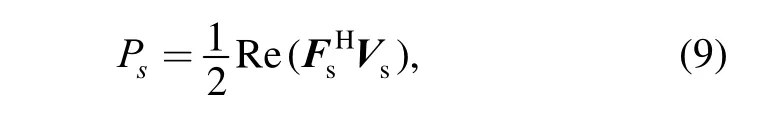
where the symbol H represents the transpose and conjugate of a matrix.
As shown in Eqs. (7), (8), the response characteristics of the isolation system are the superposition of the primary and control source components. All quantities are expressed in the frequency domain.
Then Eqs. (7), (8) can be partitioned into a control variable component, producing
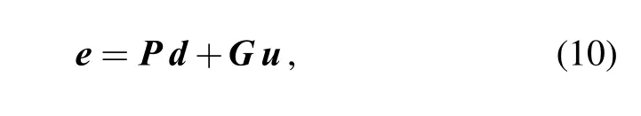
where the generalized vector e is a vector of the quantities being controlled, and d denotes primary force quantities. P and G are, respectively, the passive and active cancellation path transfer function matrices, which can be determined by mobility matrices in Eqs. (1), (4) and (5).
As stated above, in many instances, the most useful performance index is considered to be the vibratory power that propagates into the supporting structure. In this paper,a modified control strategy comprising a combination of the vibratory power transmission and the sum of the squared control forces, is proposed to allow the optimal control signal to satisfy the control force constraints:

where W, R are respectively, the vibration level weighting and control weighting matrices. As suggested by their names, these matrices weight the relative importance of attenuating the response of certain variables and limiting the control effort. That is, the active control force can be varied with respect to response level to achieve a combined performance index. This can be implemented in active control system with an adaptive strategy, in which a measure of the system output is used to adjust the control system to provide desired performance characteristics.
By combining Eq. (10), the optimal control force vector can be obtained using the same technique as used in Ref. [16]:

A block diagram of the feedforward control system is shown in Fig. 3, where all quantities are expressed in frequency domain.
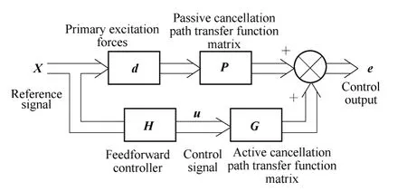
Fig. 3. Block diagram of feedforward control of an isolation system
3 Numerical Results and Discussion
In the numerical analysis, a two-isolator system is investigated, in which periodic combined excitation forces,including vertical and transverse excitation forces and a rotational moment acting in the same plane, are assumed to be applied on the rigid body.
The data of the passive system referring to reference[11]are used in the numerical calculations. The transmission characteristics of the example system with passive mounts alone were discussed in reference[21], in which the total power transmission into the flexible rectangular plate from all mounts is analysed by identifying the vibration modes corresponding to the coupled isolation system. The influence of the resonances of the resilient mount on the isolation performance is also demonstrated.
The cost functions that will be investigated for minimization are the total power transmitted into the plate,with or without control force constraints. First, control strategies in the absence of control force weighting are evaluated by comparing the total power transmission reduction with that achieved with the passive system alone.Then the magnitudes of the control forces required for achieving the maximum power transmission reduction are investigated.
3.1 Power transmission reduction and required control forces for ideal control strategies
For the control strategy without control force constraints,the power transmission characteristics are plotted in Fig. 4.Fig. 4 shows that active isolation is not only able to attenuate the resonances of the rigid body modes (at about 4–7 Hz), but is especially effective in attenuating resonance peaks of the flexible plate. At the first two resonant frequencies of the plate (17.7 Hz and 34.2 Hz), more than 50 dB total power reduction can be obtained with active control.
It is noted that the isolation performance degrades at higher frequencies of about 500 Hz. The degradation could be as high as 20–30 dB. This can be explained by the presence of the first longitudinal mode in the passive mounts(403.1 Hz). The internal resonances within the passive mounts also degrade the power transmission of the passive isolation systems, as discussed in more detail in Ref. [21].
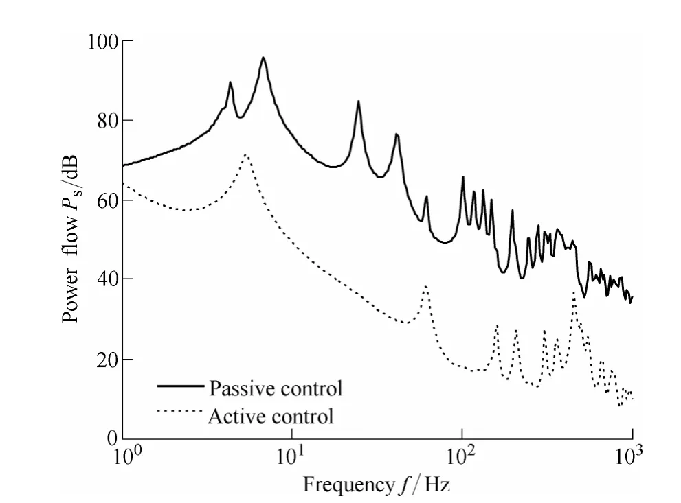
Fig. 4. Power transmission for the strategy without control force constraints
The above results estimated the maximum achievable reduction in vibration power flow on the assumption that ideal actuators with high force capabilities are available. It is expected that the integrated active-passive isolation systems would reduce the total power output without leading to control force requirements which are in excess of the primary forces generated[9]. However, in practical instances, the magnitude of the required control force may not be supplied by actuators or force-generators of reasonable size. For the performance characteristics presented in Fig. 4, the ratio of the modulus of the control forces to the modulus of the primary vertical force generated (u/Fpa) is plotted in Fig. 5.
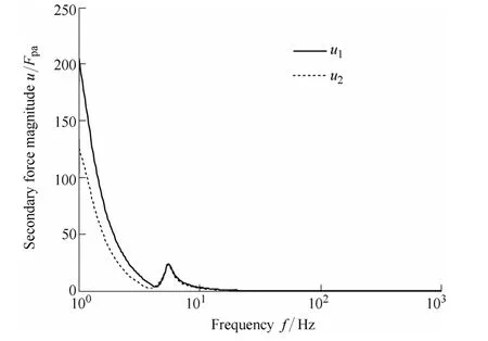
Fig. 5. Modulus of the control force required for the strategy without control force constraints
It can be seen that large amplitude control forces are required to achieve the theoretically predicted control performance. At lower frequencies (<10 Hz) the magnitude of the control force required is much higher than that of the primary vertical force. For the frequency range over which the resonant peaks of the rigid body modes appear (at about 4–7 Hz), the largest required control force is about 20 times the primary vertical force. In other words, for large machines or vibrating bodies, more powerful actuators with prohibitively large mass or space will be needed to develop the required control force, and in most cases this is likely to be impractical.
Note that the value of the control force u1for actuator 1,which represents the right actuator as shown in Fig. 1, is somewhat higher than that of actuator 2. Detailed mechanism involved here has only recently been considered, and are still under investigation.
Although the magnitude requirement for the control forces is significantly reduced as the frequency of excitation increases, as shown in Fig. 5, the frequency range over which active control is urgently desired is limited to lower frequencies, especially at frequencies around the resonances of rigid body modes.
3.2 Influence of control force constraint on power transmission reduction
In this section the performance of the active isolation systems is estimated for combined cost functions, in which both the vibration power reduction and required control forces are taken into account. As described in Eq. (11), the control matrices W and R weight the relative importance of attenuating the power transmission and limiting the control effort. In this simulation, the maximum achievable control force is constrained to be the same order of the magnitude as the primary vertical force. Such a consideration is for no other reason than to provide a basis for the discussion of the modified algorithms used in active isolation.
The performance characteristics for the active-passive isolation system, including control force constraint, are shown in Fig. 6 and Fig. 7. As is expected, when the control forces are included in the cost functions, the magnitude of the control forces can be reduced to satisfactory levels,however, the price that has been paid is that the total power transmission has increased substantially compared to the control strategies with no control force constraint, as shown in Fig. 4.
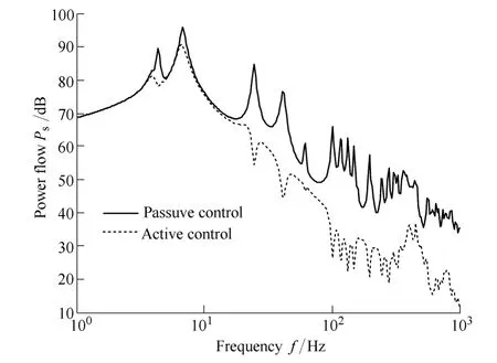
Fig. 6. Power transmission for the strategy with control force constraints

Fig. 7. Modulus of the control force required for the strategy with control force constraints
It can be seen in Fig. 6 and Fig. 7 that at frequencies over which the first two resonant modes of the plate appear, a predicted power transmission reduction of more than 20 dB can be obtained with relatively small control forces. But at frequencies over which the rigid body modes dominate, the resulting isolation systems can only achieve a 5–10 dB power transmission reduction. And at off-resonance frequencies, little or no reduction in power transmission is obtained by using active mounts, as demonstrated in Fig. 6.This is a major difference between the control strategies with and without control effort constraint.
It can also be seen in Fig. 6 that the results due to the wave effects of the elastic mounts are similar to those corresponding to the control strategies shown in Fig. 4 where the resonant peaks of the elastic mounts cannot be attenuated and as a result, induce more wave power.
Also of particular note is the frequency range over which the maximum magnitude of the control force is desired. It can be seen in Fig. 7 that the curves for the control force requirement are, however, very different from the case with control force constraint excluded in the cost function, as shown in Fig. 5. In the case considered here, the maximum magnitude of control force is required at frequencies corresponding to the rigid body modes (at about 4 Hz and 7 Hz). In conclusion, the rigid body modes require a great deal of control effort for a relatively small reduction in power transmission.
The curves in Fig. 8 and Fig. 9 represent the power flow characteristic and magnitudes of the control forces for the passive-active isolation system when only vertical excitation force is applied on the rigid body. The values of the control force weighting parameters r1, r2in matrix R for the two actuators are designed to be the same due to the symmetrical nature of the problem. In such a case, the value of each of the two control forces will be the same. As shown in Fig. 8, the curve follows the expected form for the isolation system with only one rigid body mode present.Results are obtained for the combined control strategy of total power flow minimization as the control force weighting parameters are varied.
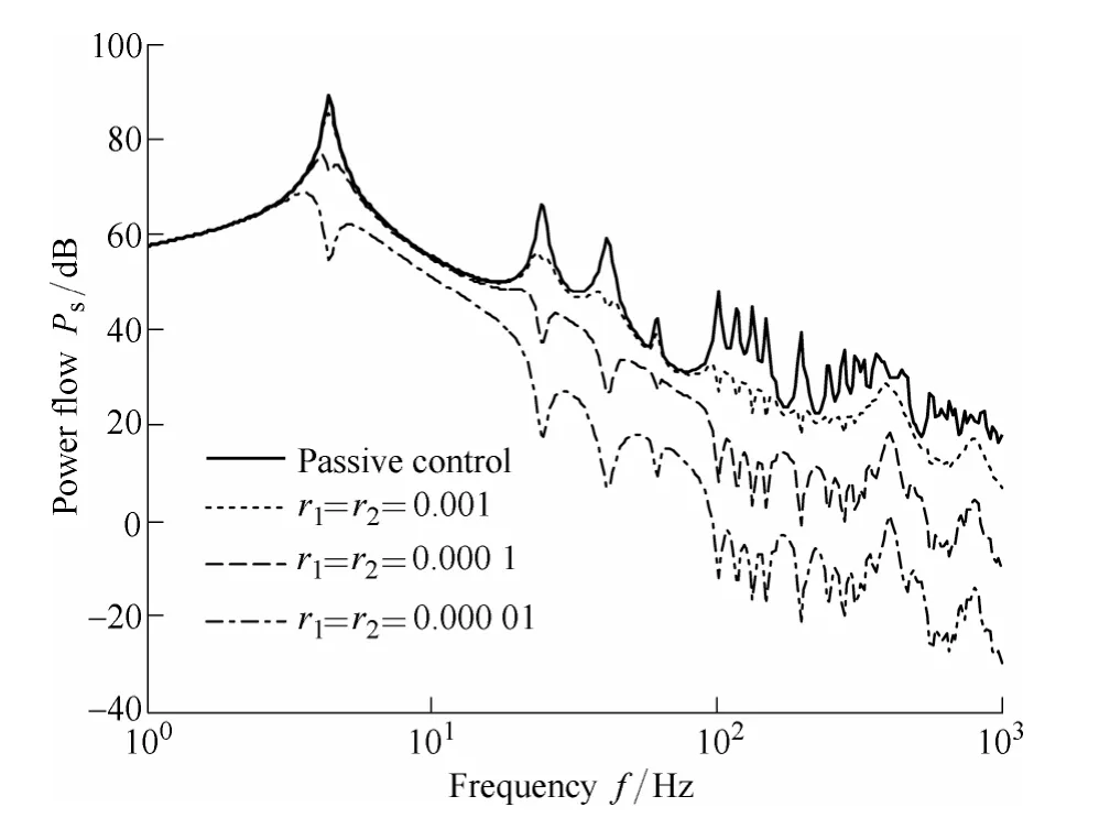
Fig. 8. Power flow for the control strategy of minimizing both total power transmission and the control forces when only a vertical primary force is applied to the rigid body

Fig. 9. Modulus of the control force required for the performance criterion illustrated in Fig. 8
It is shown in Fig. 8 that the power flow reduction of the passive-active isolation system is influenced by the weighting parameters assigned to the control forces. The peak response of the isolation system is more effectively attenuated as the weighting parameters r1, r2are decreased,while the magnitude of the required control force increases.As shown in Fig. 9, the power flow reduction in the rigid body mode is about 10–15 dB, and the reduction in the first two resonant modes of the flexible plate is 20–30 dB, when the maximum magnitude of each of the two the control forces is approximately equal to 1.5 times the magnitude of the primary vertical excitation force. It is also shown in Fig.8 and Fig. 9 that progressively greater reduction in vibration power flow can be achieved as the magnitude of the control force increases.
The numerical results illustrated in this section demonstrate that the passive-active isolation system removes the necessity for the mounted natural frequency to be very much lower than the excitation frequency, and can give low power flow transmission over a broader frequency range than possible with the passive mount alone. The resonant responses of the isolation system may be effectively attenuated by combined control strategies with the control force weighting included in the cost functions, provided that the control force actuator is able to produce similar force amplitudes to that of the vertical excitation force.
4 Conclusions
(1) The behavior of an integrated active-passive isolation system and the effect of control force constraint on the power flow reduction are evaluated. A generalized cost function was formulated in the frequency domain to minimize the combination of the vibration power flow reduction and the squared magnitude of the control forces.
(2) Comparisons of the performance characteristics of the proposed control strategies reveal that without control force constraints in the cost functions, the ideal control strategies give significant power flow reductions over a broad frequency range, but the large control force amplitudes required may be impractical for active mounts of a reasonable size.
(3) For control strategies with control force constraints,the maximum magnitude of the control force is required for the attenuation of the rigid body modes. At frequencies over which the first two resonant modes of the plate appear,a predicted power transmission reduction of more than 20 dB can be obtained using appropriately small control forces.But at frequencies over which the rigid body modes are present, the resulting systems can only achieve a 5–10 dB power transmission reduction.
(4) At off-resonance frequencies, little or no power flow reduction can be obtained by using active mounts with control forces constrained to a reasonable level(less than 60% of the primary force). On the other hand, allowing unlimited control force amplitudes allows substantial power transmission reductions to be achieved over the entire frequency range.
(5) The wave effects in the elastic passive mounts result in an increase of power transmission in high frequency range for both passive and active isolation systems.
[1] SNOWDON J C. Isolation of machinery vibration from non-rigid substructures using multiple anti-vibration mountings[J]. Journal of the Acoustical Society of America, 1973: 102–127.
[2] GOYDER H G D, WHITE R G. Vibrational power flow from machines into built-up structures. II. Wave propagation and power flow in beam-stiffened plates[J]. Journal of Sound and Vibration,1980, 68(1): 77–96.
[3] PINNINGTON R J. Vibration power flow transmission to a seating of vibration isolated motor[J]. Journal of Sound and Vibration, 1987,118(3): 515–530.
[4] FULLER C R. Active control of vibration[M]. London: Academic Press, 1996.
[5] BIES D A, HANSEN C H. Engineering noise control: theory and practice[M]. London: Taylor & Francis Ltd, 2012.
[6] HANSEN C H, SNYDER S D, QIU X, et al. Active control of noise and vibration[M]. 2nd ed. London: CRC Press, 2012.
[7] HOWARD C Q. A new cost function algorithm for adaptive-passive vibration and acoustic resonators[C]//Proceedings of ACOUSTICS,Gold Coast, Australia, November 2–4, 2011: paper number, 62.1–6.
[8] WANG Yanan, LU Zhenhua. Optimal design method of power-train mounting system for generalized force transmissibility reduction[J].Journal of Mechanical Engineering, 2011, 47(11): 52–58. (in Chinese)
[9] JENKINS M D, NELSON P A, PINNINGTON R J, et al. Active isolation of periodic machinery vibrations[J]. Journal of Sound and Vibration, 1993, 166(1): 117–140.
[10] PAN Jiaqiang, HANSEN C H. Active control of power flow from a vibrating rigid body to a flexible panel through two active isolators[J]. Journal of the Acoustical Society of America, 1993,93(4): 1947–1953.
[11] GARDONIO P, ELLIOTT S J, PINNINGTON R J. Active isolation of structural vibration on a multiple-degree-of-freedom system[J].Journal of Sound and Vibration, 1997, 207(1): 61–93.
[12] SUN Y G, SONG K J, MAO Y H. Dynamic analysis of an active flexible suspension system[J]. Journal of Sound and Vibration, 2002,249(3): 606–610.
[13] REDMAN-WHITE W, NELSON P A, CURTIS A R D. Experiments on the active control of flexural wave power flow[J]. Journal of Sound and Vibration, 1987, 112(1): 187–191.
[14] SOMMERFELDT S D. Multi-channel adaptive control of structural vibration[J]. Noise Control Engineering Journal, 1991, 37(2),77–89.
[15] HOWARD C Q. Active isolation of machinery vibration from flexible structures[D]. Adelaide: The University of Adelaide, 1999.
[16] ELLIOTT S J. The behaviour of a multiple channel active control system[J]. IEEE Transactions on Signal Processing, 1992, 40(5):1041–1052.
[17] ELLIOTT S J, BAEK K H. Effort constraints in adaptive feedforward control[J]. IEEE Signal Processing Letters, 1996, 3:7–9.
[18] QIU Xiaojun, HANSEN C H. Applying effort constraints on adaptive feedforward control using the active set method[J]. Journal of Sound and Vibration, 2003, 260 (4): 757–762.
[19] SUN Lingling, SONG Kongjie. Transmission matrix method for multi-dimensional vibration analysis of complex mechanical systems[J]. Chinese Journal of Mechanical Engineering, 2005,41(4): 38–43. (in Chinese)
[20] SOEDEL W. Vibrations of shells and plates[M]. New York: Marcel Dekker Inc, 1993.
[21] SUN Lingling, LEUNG A Y T Leung, SONG Kongjie. Vibration power-flow analysis of a MIMO system using transmission matrix approach[J]. Mechanical Systems and Signal Processing, 2007,21(1): 365–388.
 Chinese Journal of Mechanical Engineering2014年3期
- Chinese Journal of Mechanical Engineering的其它文章
- Theoretical Analysis and Experimental Verification on Valve-less Piezoelectric Pump with Hemisphere-segment Bluff-body
- Carbody Structural Lightweighting Based on Implicit Parameterized Model
- Prediction-based Manufacturing Center Self-adaptive Demand Side Energy Optimization in Cyber Physical Systems
- Numerical Simulation and Analysis of Power Consumption and Metzner-Otto Constant for Impeller of 6PBT
- Proceeding of Human Exoskeleton Technology and Discussions on Future Research
- A Novel Estimating Method for Steering Efficiency of the Driver with Electromyography Signals