
Unsteady Flow Simulations in a Three-lobe Positive Displacement Blower
2014-03-01 01:48LIUXiaominandLUJun
LIU Xiaomin and LU Jun
School of Energy and Power Engineering, Xi’an Jiaotong University, Xi’an 710049, China
1 Introduction
The positive displacement blower can provide higher air pressure and greater air flow rate than the conventional pump due to a high speed with non-contact technique. It is widely used in the process of fluid transport and pressure supply, such as mining, smelting, oil refining, chemical industry, and environmental protection.
Fig. 1 is the sketch of the positive displacement blower with three-lobe rotors. The right rotor, which is the driving rotor, is driven by the motor shaft. The right rotor engages with the left rotor, which is the driven rotor. The rotors rotate in a reverse direction. When the driving and driven rotors start disengaging, the consequent low pressure fluid is sucked. With further rotation of rotors, the fluid is trapped in between the cavity formed by the rotors and the casing of positive displacement blower. Then, the fluid is carried towards the discharge side of positive displacement blower. In one working period, the fluid is compressed and transported from the inlet to the outlet via the cavity. In this figure, φ represents the angular position of the left rotor and φ=0° represents the initial position of two rotors. At the moment shown in this figure, the left rotor has rotated 30°counter-clockwise.
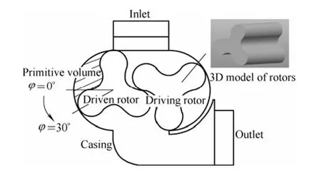
Fig. 1. Sketch of positive displacement blower
To improve the performance of positive displacement blower and reduce the aerodynamic noise induced by the airflow pulsation, many studies of the positive displacement blower focused on the optimal design of the cross section and rotor shape[1–9]. However, the study on the internal flow status of the positive displacement blower is still insufficient. SORENSON[10]provided a two-dimensional computer simulation of a three-lobe roots blower for using as a positive displacement supercharger.Three to five control volumes existing at various times in the supercharger cycle were considered and the supercharger performance was obtained. JOSHI, et al[11],reported the results of a numerical study on two-lobe multi-recompression heater with the leakage flows. But a quasi-steady numerical simulation was performed only for a single angle of rotation while the computational model was simplified to a two-dimensional analysis. The flow information along the rotor length is still missing. WANG,et al[12], simulated numerically the two dimensional interior flow fields of roots blower. They thought that the backflow impact intensity of three-lobe rotor was smaller than that of two-lobe rotor. OHTANI, et al[13], studied the effects of the casing shape of the positive displacement blower on the aerodynamic noise by the theoretical analysis. CHYANG, et al[14], used the experimental method to study the relationship between the rotating speed of rotors, the airflow velocity and pressure pulsation. However, the accuracy of result is difficult to ensure because of the environmental impact and measurement error in experimental measurement, HOUZEAUX, et al[15],developed an innovative algorithm to simulate the fluid flow of a gear pump. VOORDE, et al[16], applied fictitious domain method to study three-lobe pump and tooth compressor. LIU, et al[17–19], used the renormalization group k-ε turbulent model to solve the governing equations to describe the flow fields in a three-lobe positive discharge blower. KANG, et al[20], evaluated the fluid characteristics of a lobe pump as well as factors that could affect the performance of the lobe pump by using computational fluid dynamics(CFD) method. However, most of above researches were applied to only several strict cases within laboratorial limits and the numerical calculations were performed on two-dimensional or quasi three-dimensional flow in the positive displacement blower. These studies have stressed the growing importance of numerical methods in the description of the three-dimensional unsteady flows for the positive displacement blower applications. By numerical simulation, the more complete inner flow characteristics can be revealed at cheaper cost and shorter time.
In this paper, the numerical simulation of the three dimensional unsteady flow in the three-lobe positive displacement blower is performed for the first time by using the commercial CFD software SC/Tetra[21]. The main goal of the presented research is to understand deeply the special flow characteristics in the positive displacement blower. Especially, some relevant flow information in the positive displacement blower with the consideration of the three-dimensional and unsteady effects coupled with the temperature variation is presented. The studied results will provide helpful references for modifying the original geometry to improve the aerodynamic performance of the positive displacement blower.
2 Numerical Methods
2.1 Computational model
According to the internal flow characteristics of positive displacement blower, the three-dimensional computational model on the positive displacement blower was generated by Pro/E software, as shown in Fig. 2. In order to simplify the computational model, some appearance characteristics of the blower which don’t contact with the fluid and some components which don’t affect the flow state, such as gears,gear boxes, bearing in the figure were ignored. The length,width and height of this model is 347.5 mm, 350 mm and 315mm, respectively. For convenience of the analysis, we defined three sections in Fig. 2: section A, section B and section C, respectively corresponding to the axial intermediate section, rectangular inlet section in which the fluid begins to enter the cavity of the positive displacement blower and outlet section of the positive displacement blower.

Fig. 2. 3D geometry of the positive displacement blower generated by Pro/E
2.2 Flow governing equations
Thermal fluid commercial software SC/Tetra is adopted to perform the numerical simulation of the three dimensional unsteady compressible turbulent flow in the three-lobe positive displacement blower. The flow governing equations, which include continuity equation,momentum equation, energy equation and the equation of state, are as follows:


For the turbulent flow, the renormalization group(RNG)k-ε turbulent model[22]is used because the RNG k-ε turbulent model can fully take the effect of rotation into consideration and effectively simulate the turbulent separated flow. The transport equations of RNG k-ε turbulent model are as follows:
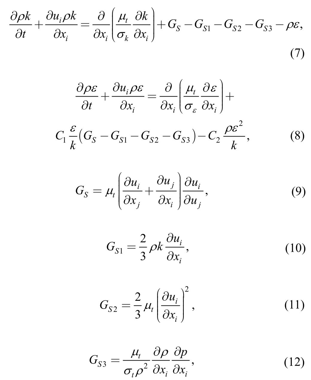
where the turbulent eddy viscosityand the constants in the turbulent flow model arerespectively, and

2.3 Boundary conditions
The pressure inlet boundary conditions were applied at the inlet of the intake region of the positive displacement blower. The pressure outlet boundary conditions were adopted at the outlet of the discharge region of the positive displacement blower. At the inlet boundary, the relative total pressure is set as 0 Pa and the inlet total temperature is 24 ℃.At the outlet boundary, the static pressure is assigned to 58 800Pa and the total temperature is 80℃according to the designed operating condition. The working fluid is the air. The reference pressure is 101 325 Pa. No slip condition is used in the solid wall. The time step is decided by Δt=CFL·Δx/max, where CFL is Courant number, Δx is grid distance, andmaxis the maximum velocity scale.
In the numerical simulation, the second-order upwind difference scheme (MUSCL scheme) is applied to the convective terms and the accuracy weighted scheme is applied to the diffusive terms. The first-order implicit scheme is used to assure the accuracy of the time derivative terms.The pressure correction method is SIMPLEC algorithm.
To determine whether the solution has converged, the residuals at each time step are monitored. For current research, the rotating speed of the positive displacement blower rotors is 1250 r/min, the time step Δt is 1.2×10⁻⁵s,and the convergence criterion for the residual tolerance is 1.0×10⁻⁶.
2.4 Grid generation
In order to generate grid system and define working zones, the model of the three-lobe positive displacement blower including rotor and casing sketched in Pro/E is imported to the preprocessor of software SC/Tetra. The size of the mesh in the computational region is controlled by the octree scheme provided in the software SC/Tetra. Start with a cube (root octant) that completely surrounds the entire model and divide it into eight cubes recursively to create a set of cubes that fill up the entire model region. This is the concept of octree, and each cube is called an octant. First,octree which determines the size of mesh is created. And then, surface mesh and volume mesh (tetrahedral mesh) are automatically executed based on the size of the octant.
The flow field consists of the stable casing region without the rotating rotor region. Considering the variation of computational region, the overset mesh, in which computational mesh of the rotor region can overlap with the casing region, is used to match the requirement of practical flow. Moving mesh conditions are defined according to the moving characters of rotors on the slave regions, i.e., the rotor regions. Meanwhile, the master region, i.e., the casing region, is always stable. The solid property is specified to the rotors in the slave region and the mesh is generated in the rotors.
The mesh of the computational region is displayed in Fig. 3(a). The numerical model consists of about 65000000 nodes. In order to check the mesh quality, h-ratio is used to represent the grid twist rate. As shown in Fig. 3(b), h-ratio is defined by the ratio of the inscribed circle of a tetrahedral element to the circumscribed circle. In this study, h-ratio for all elements here are larger than 0.03.

Fig. 3. Mesh distributions of the positive displacement blower
Nodes on the outer boundary of the slave region communicate with master elements surrounding such slave nodes by interpolation. Therefore, in the communicated region, enough fine mesh is generated near the contact surface. Two layers of prism elements, which are also called boundary layer elements, are inserted on the surfaces of rotors to improve the accuracy of calculation. The thickness of the first layer determines the normal distance to the first off-wall nodes and also changes the value of y+.For the turbulent flow calculation, the suitable value of y+is required. If most of y+is larger than 100, it is recommended to decrease the thickness of the prism layer by changing the parameters for the prism layer insertion. If most of y+is smaller than 30, it is recommended to increase the thickness of the prism layer or use a low-Reynolds number turbulence model instead of a high-Reynolds number turbulence model. In the computational model, the value of y+varies from 30 to 100, which means the thickness of the first layer is reasonable.
2.5 Numerical validation
The performance of the positive displacement blower obtained from the numerical calculation is shown in Fig. 4.Through comparing the experimental measurements, it can be found that the maximum relative error between the calculated and experimental results is less than 2.15% at the minimum flow rate conditions. This shows that the numerical model and the computational method used in this study are effective. The numerical validation is also discussed and confirmed in Ref. [23].

Fig. 4. Performance curve of the positive displacement blower
In the design condition, the variation of the inlet mass flow rate of the positive displacement blower with time is shown in Fig. 5. It can be seen that the pulsation of flow rate in the positive displacement blower is relatively large in startup process and the variation is stochastic. After a period of startup time, the flow rate of the positive displacement blower shows regular periodic variation in the range of 0.04 kg/s to 0.24 kg/s with the rotation time changes. This means the flow state in the positive displacement blower entering into a stable stage. In a rotor rotation period, because of the interaction of two rotors, the flow rate shows six harmonic changes over time and the frequency of this change is exactly twice the number of positive displacement blower’s blades. This proves that the numerical results in the present study can be used to reveal the motion state of the positive displacement blower rotors.

Fig. 5. Variation of the inlet mass flux of the three-lobe positive displacement blower with time
3 Results and Discussions
3.1 Velocity field
Fig. 6 shows the variation of the velocity vector in the positive displacement blower with three lobes in different positions from φ=20° to φ=80°. The scale of velocity vector is set in the range of 0 m/s to 20 m/s in order to show better the whole velocity field of section A.
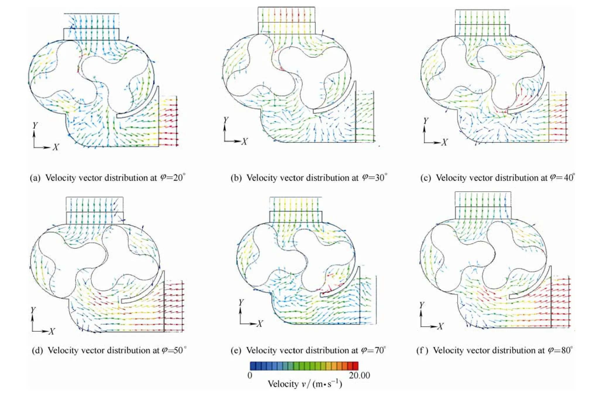
Fig. 6. Variation of velocity vector with the rotation angle φ
As shown in Fig. 5, the variation period of flow rate and flow field is 1/6 of the whole cycle, and the corresponding phase angle is 60°, so the six positions of the rotors shown in Fig. 6 represent one of the fluctuation periods of flow rate.
For the limitation of the length of this paper, the flow field at φ=60° is omitted in following analysis because the trend shown in Fig. 5 from φ=50° to φ=70° is consistent. It can be seen from Fig.6 that the inlet flow rate gets the minimum value at φ=20° and φ=80°, and reaches the maximum value at φ=30°. It can be seen from Fig. 6 that the inlet velocity deviates from the vertical direction of inlet when φ=20° and φ=80°, which leads to the corresponding minimum flow rate.That indicates the rotational position of the rotors will affect the distribution of the inlet velocity of the positive displacement blower. On the other hand, the outlet velocity varies rapidly with change of angle φ. According to the comparison between the inlet velocity and the outlet velocity,it is found that the fluctuation of outlet velocity is much larger than that of inlet velocity.
Fig. 7 shows the distribution of velocity vectors in section A at φ=0°. The maximum of velocity has reached 121 m/s.Compared with other regions, velocities in three gaps,including gap A, gap B and gap C, are much larger,especially in gap A and gap C, which is between the casing and rotors. Moreover, the flow directions in three gaps are all in the opposite direction of the main flow.
The change of the internal flow velocity shows that the high pressure at the outlet has a strong influence on velocity distribution of the whole region within the positive displacement blower, making the gaps filled with high-speed backflow, which will inevitably lead to significant energy dissipation.
3.2 Pressure field
Pressure fluctuations in the positive displacement blower are known to play a crucial role in understanding and predicting the unsteady flow and noise generation mechanisms. Fig. 8 shows the variation of static pressure distribution of three-lobe positive displacement blower over time. The variation range of the pressure is from –6000Pa to 65 000 Pa. As can be seen from Fig. 8, the pressure in both of the intake and exhaust region remains relatively stable. But pressure of the former fluctuates around a lower value because the presence of rotors isolates intake region from the exhaust region, whose pressure fluctuates around a higher value. From the variation of static pressure distribution obtained by the numerical calculation, the most dramatic variation occurs in the primitive volume,especially when it connects with exhaust region, just as shown in φ=30°, φ=40° and φ=50°. This is determined by the working principle of the positive displacement blower:the connecting process of primitive volume and exhaust region is the working process of gas compression achieved by reflux and pressure equalizing.

Fig. 7. Distribution of velocity vectors in section A within the positive displacement blower at φ=0°

Fig. 8. Variation of pressure distribution with the rotation angle φ
Fig. 9 shows the pressure contour of section A and the local pressure distribution of region A when the rotation angle is 0 degree. It can be seen that the high pressure zone distributes in the primitive volume which has been in contact with the exhaust region. From the local pressure distribution in region A, we found that there still appears obvious pressure gradient near the open gap. This means in a rotation cycle of rotors, when the gas compression of positive displacement blower starts, there exists dramatic process of reflux and pressure equalizing around the gap between the primitive volume and exhaust region.
To better reveal the pressure distribution in the positive displacement blower, five points including point A, point B,point C, point D and point E, are particularly selected. As shown in Fig. 10(a), the corresponding locations are the inlet, the region where the gas flow into the cavity, the region where the gas flow out of the cavity, the region where the gas flow out of the exhaust region, and the outlet,respectively. The pressure variation with time is shown in Fig. 10(b). It is found that the change trend of the pressures on the points B, C and D are the same: first increases and then decreases, at last increase again, which means the pressure change trend is not relevant to the location within the positive displacement blower, but only relevant to the time or the rotation angle. The pressure fluctuation amplitude of these points is greater than 20 kPa. For points A and E located on the inlet and outlet boundary, the pressure is set respectively.

Fig. 9. Pressure contour within the positive displacement blower and the corresponding region A at φ=0°
The numerical results indicate that pressure pulsation within the positive displacement blower not only appears in the primitive volume, but also appears in the entire flow region including intake and exhaust areas, and the pressure pulsation is really large. However, the amplitude of pulsation at each position is not the same. The amplitude of pressure pulsation at point B is the maximum and at point D, the amplitude of pressure pulsation is the minimum apart from point A and point E. This indicates that the pressurization process of the positive displacement blower is very complicated.
3.3 Temperature field
The variation of temperature with the rotation angle φ is shown in Fig. 11. It can be seen that during the process of rotating, the highest temperature, which can reach 99.5 ℃when the rotation angle φ is 50°, appears in the primitive volume. After enough gas with low temperature flows into the primitive volume and mixes with the gas with high temperature, the gas temperature in the primitive volume gradually falls (at φ=80°). In the exhaust region, there always exist some areas with high temperature. In the primitive volume, the gas temperature is low before the compression process begins (from φ=20° to φ=30°), and then rises quickly after the compression process finishes(from φ=40° to φ=50°). This indicates that in the positive displacement blower, the flow status and the temperature distributions are different in different regions, so the analysis of the temperature field is indispensable to reveal the detailed flow information within the positive displacement blower.

Fig. 10. Variation of pressure at specific point with the rotation angle φ
The streamline distributions in the section A of the positive displacement blower are shown in Fig. 12. When the rotation angle φ is 30°, the primitive volume of driving rotor has not completely communicated with the exhaust region, but at this moment the air flow is very disorderly in the blower,especially near the exhaust region. When the rotation angle φ is 80°, the primitive volume of driving rotor has completely communicated with the exhaust region. At that time, flow vortex appears immediately in the primitive volume.
According to the analysis of the distribution of the velocity vectors shown in Fig. 7, we could conclude the flow vortex is caused by the backflow at the reverse pressure gradient. Then these vortexes are bound to produce, develop and dissipate. The resulting pressure pulsation is the main reason of aerodynamic noise.
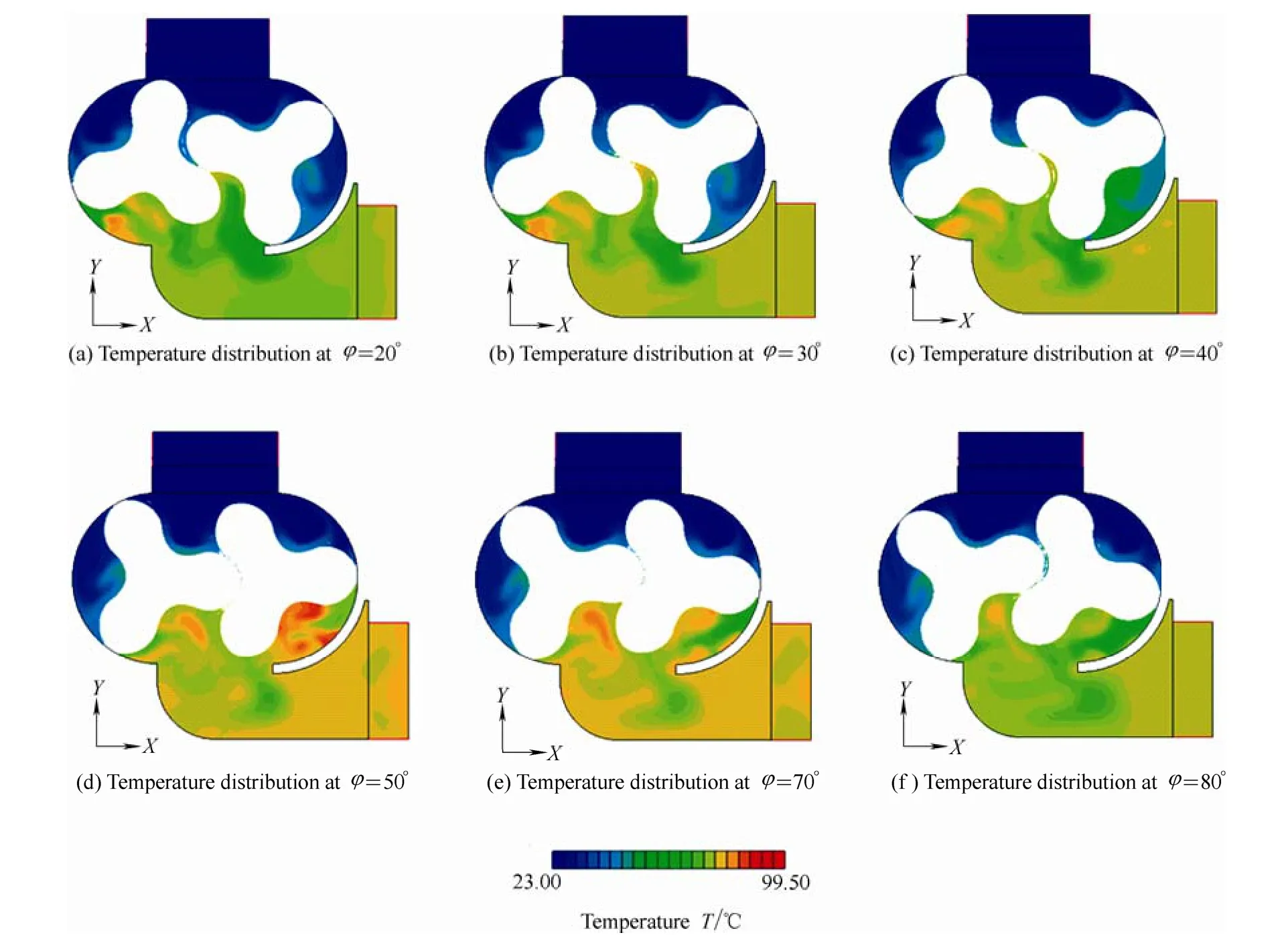
Fig. 11. Variation of temperature with the rotation angle φ in the positive displacement blower

Fig. 12. Streamline distributions in section A varied with the rotation angle φ
The vortical structures are very important for us to understand the unsteady flow and temperature distribution in the positive displacement blower. As shown in Fig. 12,the position of the vortexes in the primitive volume coincides closely with the position of the high temperature area when the rotation angle φ is 30° and 80°, respectively.It indicates the vortexes distribution and temperature distribution are related to each other. The correlation actually reflects the coupling relationship of the velocity field and the temperature field: the energy dissipates in the way of heat while the flow field becomes disordered. Meanwhile, we observed in Fig. 9, there is more intense variation of pressure in the regions where the vortex occurred.
From the above numerical analysis, it can be seen that with the establishment of relationship between velocity field, temperature field and pressure field, the cause of the aerodynamic noise of the positive displacement blower is profoundly revealed. In other words, in order to reduce the aerodynamic noise, we have to suppress the airflow pulsation in the positive displacement blower by optimal design of rotor shape and cavity structure.
4 Conclusions
(1) The numerical results are compared with the experimental measurements on the variation of flow rate with the outlet pressure to verify the validity of the numerical method. The maximum relative error of the calculated and experimental values is less than 2.15%,which shows that the numerical model and computational method used in this study are effective.
(2) The internal flow of the positive displacement blower is very complex. The flow fields change rapidly with time.The pressure balance process caused by the backflow impact makes the gaps between rotors and the casing as well as the gap between two rotors filled with the reflux gas with high velocity, which can reach 121 m/s. The amplitude of pressure pulsation at most of the internal region is more than 20 kPa. During the compression process, the variation of pressure in the primitive volume is the most dramatic and the pressure gradient in the gaps is large.
[1] MIMMI G, PENNACCHI P. Analytical model of a particular type of positive displacement blower[J]. Proceeding of IMechE, Part C:Journal of Mechanical Engineering Science, 1999, 213(5):517–526.
[2] MIMMI G, PENNACCHI P. Compression load dynamics in a special helical blower: a modeling improvement[J]. Journal of Mechanical Design, 2001, 123(3): 402–407.
[3] MIMMI G C, PENNACCHI P E. Dynamic loads in the three-lobe supercharger[J]. Journal of Mechanical Design, 1999, 121(4):602–605.
[4] YAO L,YE Z, CAI H, et al. Design of a milling cutter for a novel three-lobe arc-cycloidal helical rotor[J]. Proceeding of IMechE,Part C: Journal of Mechanical Engineering Science, 2004,218(C10): 1233–1241.
[5] LIU S, NISHI M, YOSHIDA K. Impeller geometry suitable for mini turbo-pump[J]. Journal of Fluids Engineering, 2001, 123(3):500–506.
[6] HWANG Y W. HSIEH C F. Study on high volumetric efficiency of the Roots rotor profile with variable trochoid ratio[J]. Proceeding of IMechE, Part C: Journal of Mechanical Engineering Science, 2006,220(C9): 1375–1384.
[7] YAO L G, YE Z H, DAI H S, et al. Geometric analysis and tooth profiling of a three-lobe helical rotor of the positive displacement blower[J]. Journal of Material Processing Technology, 2005,170(1–2): 259–267.
[8] YE Z H, YAO L G, LAN Z H, et al. Design and cutting of three-lobe helical rotor in roots blower[J]. Chinese Journal of Mechanical Engineering, 2004, 17(Suppl.): 102–106.
[9] PENG Xueyuan, HE Zhilong, SHU Pengcheng. Design improvement on involute profile of positive displacement blower[J]. Compressor Blower & Fan Technology, 2000(3): 3–5.
[10] SORENSON S C. Simulation of a positive displacement supercharger[R]. SAE Technical Report 840244, 1984, DOI:10.4271/840244.
[11] JOSHI A M, BLEKHMAN D I, FELSKE J D, et al. Clearance analysis and leakage flow CFD model of a two-lobe multi-recompression heater[J]. International Journal of Rotating Machinery, 2006, DOI: 10.1155/IJRM/2006/79084.
[12] WANG F M, LI Y, GUO X B, et al. Study on structural design of roots blower with low noise and numerical simulation of interior flow field[J]. Journal of Shandong University of Science and Technolgy, 2010, 29(6): 55–60.
[13] OHTANI I, IWANOTO T. Reduction of noise in positive displacement blower[J]. Bulletin of the JSME, 1981, 24(189):547–554.
[14] CHYANG C, LIN Y. Influence of the nature of the positive displacement blower on pressure fluctuations in a fluidized bed[J].Power Technology, 2002, 127(3): 19–31.
[15] HOUZEAUX G, CODINA R. A finite element method for the solution of rotary pumps[J]. Computers and Fluids, 2007, 36(4):667–679.
[16] VOORDE J V, VIERENDEELS J, DICK E. Flow simulations in rotary volumetric pumps and compressors with the fictitious domain method[J]. Journal of Computational and Applied Mathematics,2004, 168(1): 491–499.
[17] LIU Zhengxian, XU Lianhuan, ZHAO Xuelu. The unsteady numerical analysis of the positive displacement blower’s internal airflow pulsation[J]. Journal of Aerospace Power, 2007, 22(3):400–405.
[18] HUANG Z F, LIU Z X. Numerical study of a positive displacement blower[J]. Proceeding of IMechE, Part C: Journal of Mechanical Engineering Science, 2009, 223(10): 2309–2316.
[19] LIU Zhengxian, WANG Dou, XU Lianhuan. Numerical simulation of unsteady discharge flow with fluctuation in positive discharge blower[J]. Chinese Journal of Mechanical Engineering, 2009, 22(2):214–220.
[20] KANG Y H, VU H H, HSU C H. Factors impacting on performance of lobe pumps: A numerical evaluation[J]. Journal of Mechanics,2012, 28(2): 229–238.
[21] Software Cradle Co., Ltd. SC/Tetra Version 9 User’s Guide Operation Manual, 2011.
[22] YAKHOT V, ORZAG S A. Renormalization group analysis of turbulence: basic theory[J]. Journal of Scientific Computing, 1986,1(1): 3–11.
[23] LIU X M, LU J, GAO R H, XI G. Numerical investigation of the aerodynamic performance affected by spiral inlet and outlet in a positive displacement blower[J]. Chinese Journal of Mechanical Engineering, 2013, 26(5): 957–966.
 Chinese Journal of Mechanical Engineering2014年3期
- Chinese Journal of Mechanical Engineering的其它文章
- Theoretical Analysis and Experimental Verification on Valve-less Piezoelectric Pump with Hemisphere-segment Bluff-body
- Carbody Structural Lightweighting Based on Implicit Parameterized Model
- Prediction-based Manufacturing Center Self-adaptive Demand Side Energy Optimization in Cyber Physical Systems
- Effectiveness of a Passive-active Vibration Isolation System with Actuator Constraints
- Numerical Simulation and Analysis of Power Consumption and Metzner-Otto Constant for Impeller of 6PBT
- Proceeding of Human Exoskeleton Technology and Discussions on Future Research