
Unified Coordinate System Model for Performance Calculation of Fix-pad Journal Bearing with Different Pad Preload
2014-03-01 01:48ZHUAibinYANGYuleiCHENWeiandYUANXiaoyang
ZHU Aibin, YANG Yulei, CHEN Wei, and YUAN Xiaoyang
Key Laboratory of Education Ministry for Modern Design and Rotor-Bearing System,Xi’an Jiaotong University, Xi’an 710049, China
1 Introduction
Fix-pad journal bearing is widely used in power equipment such as steam turbines[1]and nuclear major pump due to its advantages of strong capacity, smooth running, well vibration resistance performance and low noise[2]. Researchers both domestic and international conducted a great deal of researches on numerical calculation for static and dynamic characteristics of fix-pad journal bearings[3–6]. Calculation models of bearing evolved from the initial simplified infinite bearing model to models considering turbulent flow[7], temperature-viscosity[8–10],elastic deformation[11]and thermal deformation[12–15]in actual operating conditions, and calculation program also becomes more and more complicated. According to bearing geometric relationships, these studies classified the bearings to various forms as circular journal bearing,dislocated bearing, elliptic bearing and multi-leaf bearing.For static and dynamic characteristics calculation of each type of bearing, traditional calculation program needs to be written respectively, and various geometric formulae needs to be deduced according to different bearing structures[7],which leads to heavy workload, complicated and changeable formulae. Taking turbulent flow,temperature-viscosity, elastic deformation and thermal deformation into consideration, program based on traditional model becomes more complicated. Traditional model not only greatly increased programming complexity,but also reduced scalability and promotion of the program.
Some power units from abroad using non-standard bearing that the preload of each pad is not exactly the same.The traditional model calculation procedure is difficult to calculate, which is a serious impediment to self-development and performance check of a journal bearings. A unified coordinate system model unifying geometric description of a fix-pad journal bearing is presented in this paper, which can be applied to both standard and non-standard journal bearings, greatly reduce the programming workload for performance computing program and increase expansion, and promotion of the program. In addition, due to the unification of the various types of bearings, this model is more conducive to the performance comparison between the different types of bearings, which helps to identify different types of bearing performance variations, and promotes the development of new structural forms of bearings. Performance of a non-standard four-leaf bearing with different pad preload ratio is calculated as well as the performance parameters changing characteristic with preload ratio is analyzed.
2 Traditional Model Process
In the static and dynamic characteristics calculating process for different forms of fix-pad journal bearings, the eccentricity ratio and attitude angle of axis relative to each pad needs to be calculated firstly. Considering bearing of standard forms, such as circular journal bearing, dislocated bearing, elliptic bearing and multi-leaf bearing, the geometric relationship is not the same, so the formulae of the bearing film thickness are different. Considering non-standard forms of bearings, such as these of pads with different preload ratio or mixed bearings constitute by several forms of pads, each pad has respective different film thickness calculation formula.
Traditional model processing is based on various geometric relationships of fix-pad journal bearings, which needs to derive the eccentricity ratio and attitude angle calculation formulae for the journal center relative to each pad center based on the geometric relationship in specific types of bearings, and calculate the oil film thickness and performance coefficients of bearings individually. Since each bearing has its different geometric relationship, the eccentricity ratio and attitude angle calculation formula is various. Table 1 shows the eccentricity ratio and attitude angle calculation formulae for two commonly used types of journal bearings.

Table 1. Eccentricity ratio and attitude angle calculation formulae for two types of journal bearings
As shown in Table 1, different bearing has different eccentricity ratio and attitude angle calculation formulae,additionally, if the bearing is a mixture of different types of pads, new formulae need to be introduced again.Traditional model needs various geometric formulae which leads to heavy workload, complicated and changeable formulae, thus reduces scalability and promotion of the program. A universal computing model unifying geometric description of fix-pad journal bearing can be applied to both standard and non-standard journal bearings, which greatly reducing the programming workload for performance computing program and increasing expansion,and promotion of the program.
3 Unified Coordinate System Model
A unified coordinate system with the bearing center at the origin is established, which takes the positive direction of y-axis as the angle starting line. As shown in Fig. 1, O is the bearing center, Oiis the center of pad i, Ojis the journal center, e is the eccentric distance, θ is the attitude angle.
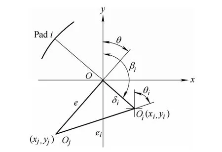
Fig. 1. Unified coordinate system of journal bearing
As shown in Fig. 1, δiis the eccentric distance of pad i,βiis the angle between eccentric distance and angle starting line, we named βithe eccentric distance angle or preload angle in dimensionless. In the unified coordinate system coordinates of Oiis:
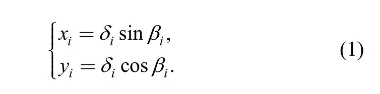
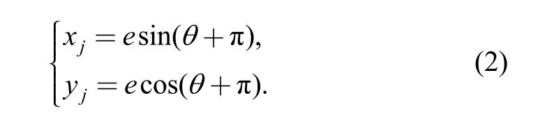
Coordinates of Ojis:
In the unified coordinate system, eccentricity ratio and attitude angle of the journal center relative to pad center can be calculated:

Eq. (3) calculates the eccentricity ratio and attitude angle of the journal center relative to any pad, which is suitable for all forms of fix-pad journal bearings.
Choosing m=δ/c and ε=e/c (c is the radius clearance)to dimensionless Eqs. (1)–(3) as Eqs. (4)–(6), respectively:

where miis the preload ratio of pad, βiis the preload angle,are dimensionless coordinates of pad center and journal center, εi, θiare the eccentricity ratio and attitude angle of the journal center relative to any pad center.
After calculation of εiand θi, dimensionless oil film thickness can be calculated by Eq. (7):

where Φ is the circumferential angle of any point in of the pad from the angle of the starting line.
The unified coordinate system model mentioned above unifies the calculation formulae of eccentricity ratio and attitude angle for any forms of fix-pad journal bearings. In this model, eccentricity ratio and attitude angle can be calculated easily with pad preload ratio and preload angle given. This model eliminates the derivation of complex and changeable geometric formulae, which is suitable for both the various standard fix-pad journal bearings and the non-standard bearings composed by pads with different preload ratios.
Pad preload ratio miand preload angle βiare parameters required for the unified coordinate system model to describe bearing geometric relationships. Unified coordinate system model describes bearing parameters with the following set:

where U defines the set of all pads in a bearing, miand βiis the preload ratio and preload angle of pad i respectively, n is the number of pads. As shown in Eq. (8), the unified coordinate system model unifies geometric description of both standard and non-standard journal bearings with different pad preload ratios.
Fig. 2 shows the layout schematic of several commonly used standard bearings. Based on the unified coordinate system mode, geometric description of theses bearings is given. Fig. 2(a) shows a circular journal bearing that can be described as {(0, 0°), (0, 180°)}; Fig. 2(b) shows a dislocated bearing with description of {(m, 90°), (m, 270°)};Fig. 2(c) shows a elliptic bearing with description of {(m,0°), (m, 180°)}; Fig. 2(d) shows a three-leaf bearing with description of {(m, 0°), (m, 120°), (m, 240°)}; Fig. 2(e)shows a four-leaf bearing with description of {(m, 0°), (m,90°), (m, 180°), (m, 270°)}.

Fig. 2. Layout of several commonly used standard bearings
4 Calculation Program Based on Unified Coordinate System Model
Calculation program based on traditional model needs eccentricity and attitude angle formulae decided by bearing types. When it comes to a non-standard journal bearing with different pad preload ratios, it is hardly impossible or special pre-process needed to conduct calculation for program based on traditional model, which reduces the versatility of the program.
As the unified coordinate system model unifies the calculation formulae of eccentricity ratio and attitude angle,program based on this model can be applied to calculate performance for both standard and non-standard fix-pad journal bearings without any other process. The program adopts unified coordinates model to describe bearing geometric parameters, and calculates oil film thickness according to Eq. (7), then solves the Reynolds equation and static bearing characteristics, finally solves the perturbation pressure to calculate the dynamic bearing characteristics.Flowchart of program according to the unified coordinate system model and traditional model is shown in Fig. 3.
5 Model Verification and Performance of Four-leaf Bearing With Different Pad Preload Ratios
The unified coordinate system model unifies geometric description of fix-pad journal bearing, which is suitable for performance calculation of both standard and non-standard journal bearing with different pad preload ratios.
5.1 Model verification
An elliptical bearing is studied to verify the validity of the unified coordinate system model. The bearing with pad span angle of 160°, l/d ratio of 0.5, elliptical ratio of 0.5.Comparisons of results by the unified coordinate system model with traditional model[17]are shown in Fig. 4 and Fig.5. The results show that static and dynamic coefficients calculated by the unified coordinate system model matches traditional model very well, which verifies the validity of the unified coordinate system model.

Fig. 3. Flowchart of program according to the unified coordinate system model and traditional model
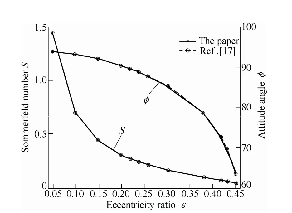
Fig. 4. Comparison of static parameters
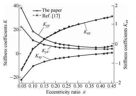
Fig. 5. Comparison of dynamic parameters
5.2 Performance of four-leaf bearing with different pad preload ratios
Taking a four-leaf bearing with pad span angle of 70°and l/d ratio of 0.5 as an example, performance is calculated with program based on the unified coordinate system model while pad preload ratio varies. Fig. 2(e)shows layout of the bearing, three cases of pad preload ratio and preload angle for the bearing are as follows:
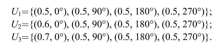
In case U1, four pads have the same preload ratio, and preload ratio of pad 1 differs from that of other three pads in case U2or U3. It is difficult for program based on traditional model to deal with case U2and U3. However, it’s easy for the unified coordinate system model, since the unified coordinate system model unifies geometric description of fix-pad journal bearings, program can process case U2and U3directly.
Based on the unified coordinate system model, both static and dynamic performance parameters are calculated by the program for the four-leaf bearing under case U1, U2or U3as shown in Fig. 6–Fig. 13.
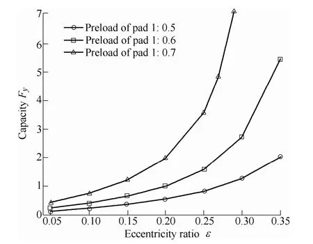
Fig. 6. Comparison of bearing capacity

Fig. 7. Comparison of Kxx
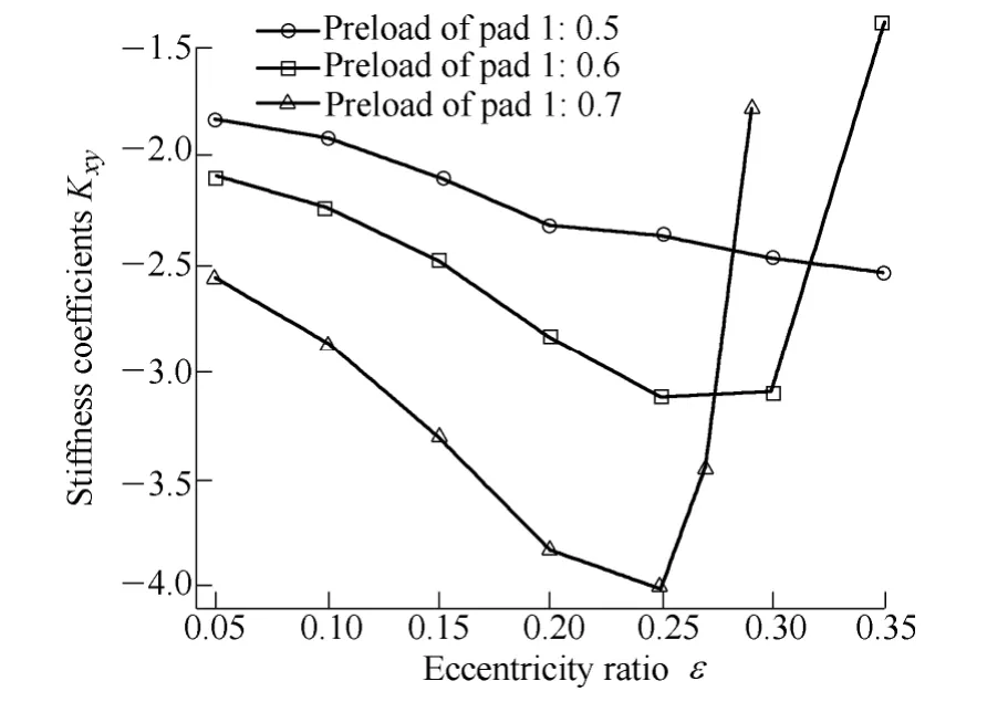
Fig. 8. Comparison of Kxy

Fig. 9. Comparison of Kyx

Fig. 10. Comparison of Kyy
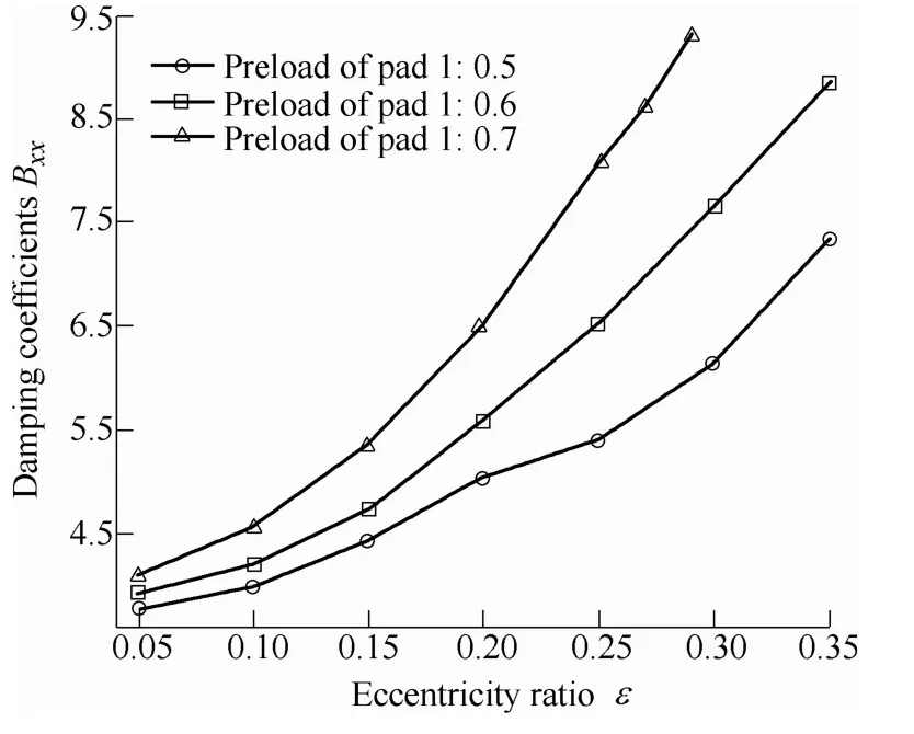
Fig. 11. Comparison of Bxx

Fig. 12. Comparison of Bxy (Bxy =Byx)
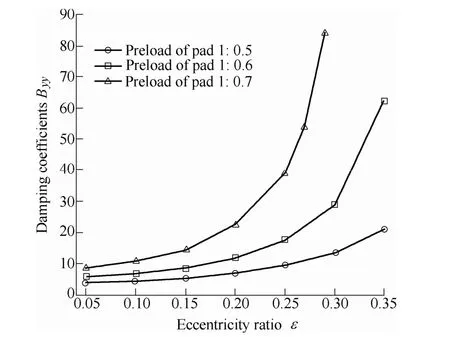
Fig. 13. Comparison of Byy
Fig. 6 shows that increasing preload ratio of pad 1 and remaining that of the other three pads unchanged lead to increasing of the bearing capacity. Fig. 7 shows that stiffness, Kxx, increases when the preload ratio of pad 1 increases, Kxxincreases marginally when the eccentricity ratio is lower than 0.1, Kxxshows a significant increase when the eccentricity ratio larger than 0.1. Fig. 8 shows that absolute value of cross stiffness, Kxy, increases gradually with eccentricity ratio when keep four pads are kept with consistent preload ratio. Keeping preload ratio of the three pads constant and increasing that of the left pad 1,absolute value of Kxyshows a significant increase when the eccentricity ratio is lower than 0.25 but a rapidly reduce when the eccentricity ratio is larger than 0.25. As shown in Fig. 9, the cross stiffness, Kyx, increases with the preload ratios of pad 1 increase. As shown in Fig. 10, stiffness, Kyy,shows a modest increase with the preload ratio of pad 1 increasing when the eccentricity ratio is lower than 0.15 and a substantial increase when the eccentricity ratio exceeds 0.15. Fig. 11 shows that damping coefficient Bxxincreases with the preload ratio of pad 1 increasing and the increase amplitude becomes larger with the eccentricity ratio increasing. Fig. 12 shows that the cross damping coefficient Bxydecreases with the increase of preload ratio for pad 1 when the eccentricity ratio is less than 0.16, the decrease amplitude reduces gradually with eccentricity close to 0.16. After the eccentricity ratio larger than 0.16,Bxyincreases with the preload ratio of pad 1 increasing and the increase amplitude also increases with the eccentricity ratio increase. Fig. 13 shows that increasing preload ratio of pad 1 and remaining that of other three pads unchanged increases damping coefficient Byy, the increase amplitude also increases with eccentricity ratio increase.
6 Conclusions
(1) The unified coordinate system model unifying geometric description of fix-pad journal bearing is presented, which can be applied to performance calculation of various standard and non-standard journal bearings with different pad preload ratios.
(2) The unified coordinate system mode adopts preload ratio miand preload angle βito describe bearing geometric relationships, fix-pad journal bearings both standard and non-standard are a describing set U={(m1, β1),…, (mi, βi),…, (mn, βn)} is provided.
(3) While preload ratio of pads differs, merely preload ratio of pad 1 increases and that of other pads is unchanged can improve bearing capacity, stiffness and damping coefficients.
[1] WEN Shizhu, HUANG Ping. Principles of tribology[M]. Beijing:Tsinghua University Press, 2012. (in Chinese)
[2] YANG Jiangang, CAI Ting, GAO Wei. Three dimensional fluid-solid coupled analytical model of steam turbine bearing[J].Proceedings of the CSEE, 2004, 24(8): 147–151. (in Chinese)
[3] ROY L, LAHA S K. Steady state and dynamic characteristics of axial grooved journal bearings[J]. Tribology International, 2009,42(5): 754–761.
[4] CHEN Chienyu, CHEN Qieda, LI Wanglong. Characteristics of journal bearings with anisotropic slip[J]. Tribology International,2013, 61(1): 144–155.
[5] MAJUMDAR B C, PAI R, HARGREAVES D J. Analysis of water-lubricated journal bearings with multiple axial grooves[J].Proceedings of the Institution of Mechanical Engineers, Part J:Journal of Engineering Tribology, 2004, 218(2): 135–146.
[6] NI Guangjian, ZHANG Junhong, CHENG Xiaoming.Characteristics of the main journal bearings of an engine based on non-linear dynamics[J]. Chinese Journal of Mechanical Engineering, 2009, 22(5): 755–759.
[7] MANESHLAN B, NASSAB A G. Thermohydrodynamic analysis of turbulent flow in journal bearings running under different steady conditions[J]. Proceedings of IMeehE, 2009, 223(8): 1115–1127.
[8] BOUYER J, FILLON M. On the significance of thermal and deformation effects on a plain journal bearing subjected to severe operating conditions[J]. Journal of Tribology, 2004, 126(4):819–822.
[9] COSTA L, MIRANDA A S, FILLON M, et al. An analysis of the influence of oil supply conditions on the thermohydrodynamic performance of a single-groove journal bearing[J]. Proceedings of the Institution of Mechanical Engineers, Part J: Journal of Engineering Tribology, 2003, 217(2): 133–144.
[10] CHAUHAN A, SEHGAL R, SHARMA R K. Thermohydrodynamic analysis of elliptical journal bearing with different grade oils[J].Tribology International, 2010, 43(11): 1970–1977.
[11] LAHMAR M, ELLAGOUNE S, BOU-SAID B.Elastohydrodynamic lubrication analysis of a compliant journal bearing considering static and dynamic deformations of the bearing liner[J]. Tribology Transactions, 2010, 53(3): 349–368.
[12] FARGERE R, VELEX P. Influence of clearance and thermal effects on the dynamic behaviour of gear-hydrodynamic journal bearing systems[J]. Journal of Vibration and Acoustics, 2013, 135(6):1014–1029.
[13] PIERRE I, FILLON M. Influence of geometric parameters and operating conditions on the thermohydrodynamic behavior of plain journal bearings[J]. Proceedings of Institution Mechanical Engineers, 2000, 214(5): 445–457.
[14] CHUN S M. Thermohydrodynamic lubrication analysis of high-speed journal bearing considering variable density and variable specific heat[J]. Tribology International, 2004, 37(5): 405–413.
[15] PANDAZARAS C, PETROPOULOS G. Tribological design of hydrodynamic sliding journal bearings-formulating new functional charts[J]. Industry Lubrication and Tribology, 2005, 57(1): 4–11.
[16] ZHANG Zhiming, ZHANG Yanyang, XIE Youbai. Hydrodynamic lubrication theory for journal bearing[M]. Beijing: Higher Education Press, 1986. (in Chinese)
[17] LUND J W, THOMSEN K K. A calculation method and data for the dynamic coefficients of oil-lubricated journal bearings[M]. New York: ASME, 1978.
 Chinese Journal of Mechanical Engineering2014年3期
- Chinese Journal of Mechanical Engineering的其它文章
- Theoretical Analysis and Experimental Verification on Valve-less Piezoelectric Pump with Hemisphere-segment Bluff-body
- Carbody Structural Lightweighting Based on Implicit Parameterized Model
- Prediction-based Manufacturing Center Self-adaptive Demand Side Energy Optimization in Cyber Physical Systems
- Effectiveness of a Passive-active Vibration Isolation System with Actuator Constraints
- Numerical Simulation and Analysis of Power Consumption and Metzner-Otto Constant for Impeller of 6PBT
- Proceeding of Human Exoskeleton Technology and Discussions on Future Research