
Impact of Heat Shield Structure in the Growth Process of Czochralski Silicon Derived from Numerical Simulation
2014-03-01 01:48ZHANGJingLIUDingZHAOYueandJIAOShangbin
ZHANG Jing, LIU Ding, ZHAO Yue, and JIAO Shangbin
School of Automation and Information Engineering, Xi’an University of Technology, Xi’an 710048, China
1 Introduction
Currently, the Czochralski is the most widely used technology in production of mono-crystalline silicon for the photovoltaic panels[1–3]. φ 300 mm wafers are widely used in the photovoltaic industry due to its cost advantage.While the wafer diameter increases from 200 mm to 300 mm, the feeding capacity is increased from 60 kg to 150 kg for each production run. The large volume of silicon melt and strong convection increases the oxygen concentration in the ingot[4–8]. Magnetic Czochralski (MCZ) method is often adopted to suppress the melt’s thermal convection and the impurity distribution in order to lower the oxygen concentration in the crystal[9–11]. But the cost is too high for photovoltaic wafers because its power consumption. During the Cz-Si growth process, some of the dissolved oxygen impurities in the melt become incorporated into the ingot,while the rest of the dissolved oxygen reacts chemically with the silicon oxide(SiO) gas and vaporizes from the free surface and is then carried away by argon gas above the free surface. Flowing argon obviously increases the evacuation of SiO. Therefore gas flow and heat shield optimization can be a way to lower the oxygen concentration in the silicon melt.
TENG, et al[12], found that in the directional solidification system(DSS), adjusting the chamber pressure changes the oxygen concentration in the melt-crystal interface. On the one hand, the oxygen concentration reduced due to the reduction in the amount of crucible surface immersed in the silicon melt. At a higher chamber pressure, the evaporation of SiO at the free surface was lower. On the other hand, the higher pressure increased the argon flow speed over the melt surface. The evaporation speed of SiO was increased.However, it is not suitable for the Cz mono-crystalline silicon furnace because adjusting the whole chamber pressure is inefficient to improve ingot quality in a large furnace. SU, et al[13–14], discussed the oxygen concentration lowered in the melt by the optimization of a heat shield and a side insulator. The heat shield reduced the heat radiation from the heater to the ingot which increased the crystallization rate. The optimized side insulator stopped the heat loss from the heater which improved the shape of the melt-crystal interface. However, the side insulator blocked the observation window and made it difficult to observe growth of crystal.
Heat shield optimization is an effective way to lower oxygen concentration at the melt-crystal interface. The fact is that the argon flow speed near melt surface is affected by the heat shield structure, and then has an effect on the evacuation of SiO. TENG, et al[15], showed that the argon flow near the crucible wall is increased by enlarging the lateral length of the heat shield bottom. The above literatures are all focused on the optimization of one heat shield design. However different heat shield structures have different impacts on the crystal growth process.
In this paper, theoretical analysis combined with numerical simulation is adopted to acknowledge the effect of different heat shields on the growth process of melt-crystal interface shape, the argon flow field, and the oxygen concentration at the melt-crystal interface, such as right-angle, inclined and composted heat shields. Based on numerical simulation, pros and cons of the above heat shield designs will be compared. The temperature gradient distribution of a large thermal field with a composite heat shield will be provided as a further reference in the thermal field design of a large diameter Cz-Si furnace. To verify the conformity, the simulation results will be compared with the real melt-crystal interface, which is obtained by the Quick Pull Separation method.
2 Mathematical Model
The configuration of a typical Czochralski furnace for producing mono-crystalline silicon is shown in Fig. 1. The geometry of the furnace configuration is axsymmetric. In order to establish a discrete system for numerical simulation, the entire furnace is subdivided into a number of block regions, as shown in the left part of Fig. 1, in which subdivision resulted in a total of 12 block regions.Each of these block regions is then discredited by a structured grid. The computational grid of all block regions in a cross-plan is shown in the right part of Fig. 1.
With the assumptions of a quasi-steady system and incompressible laminar flow of the melt, the momentum,mass conservation and energy equations for the melt flow in a crucible can be written as follows:

where v is velocity vector, g is gravity vector. ρ, μ, P, T, β,C and k are density, coefficient of viscosity, pressure,temperature, the volumetric expansion coefficient, the heat capacity and thermal conductivity, respectively. The subscript l, s, qz and gr are the relevant variables of melt,crystal, quartz crucible and graphite crucible, respectively.Eq. (1) is the Navier-Stokes equation which is the differential form of momentum conservation. The inertial force of unit volume of fluid is on the left of the equation.While on the right side, the first part is the viscous force of unit volume of fluid, the third part is the buoyancy force caused by temperature unevenness. Eq. (2) is the continuity equation and Eq. (3) represents the heat conduction of the melt. The crystal, the quartz crucible and the graphite crucible are all solid; therefore the heat-transfer equation also follows Eq. (3).

Fig. 1. Solidification furnace configuration: domain partition(left-half part) and computation grid (right-half part)
The temperature at the melt-crystal interface is equal to the melting temperature of silicon, and the energy should satisfy the Stefan condition[16–18]:

Where V is the local pulling rate, is normal to the melt-crystal interface, n is the normal direction of the melt-crystal interface, Tmis the silicon melting point and ΔH is the latent heat.
The heat shield is located very close to the crystal. Its position has great influence on the temperature distribution of the crystal ingot and the melt free surface. The temperature distribution is affected by thermal radiation effect as well as argon flow. With the installed heat shield,heat radiation and argon flow are changed, it is not reasonable to use the first boundary condition for temperature constraint. To solve this problem, heat flux equations are established to describe the crystal surface and melt free surface heat loss due to argon blowing and heat radiation.
On the crystal surface:


On the melt free surface:

Eq. (5) and Eq. (7) are boundary conditions of heat flux.The first item on the right part of the equation is the description of heat loss by argon gas flow.are radial and axial temperature gradients. q′is the heat loss by radiation. rais the diameter of crystal. L is the depth of melt volume. Eq. (6) and Eq. (8) are the radiation heat flux, the reflective heat flux and the incident heat flux,which are relevant to radiation models. δ is the heat dissipation coefficient of the convection, σ is the Stefan-Boltzmann constant, ε is radiation coefficient and Fkjis the angle between k and j surfaces, respectively.
The boundary conditions of the inner surface of the quartz crucible, the top surface of the quartz crucible and the graphite crucible are all the same with the crystal, and are derived from heat flux. In addition, using Boussinesq assumption for density calculation, density change in the control equation is only considered with gravity. While for the others, the density is considered as a constant which is the average value. As approximated shown in Eq. (9):
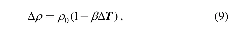
where ρ0is the average value of density, and the melt free surface used the free-slip boundary condition.
Eqs. (1)–(4) are discretized by using the Finite Element Method(FEM), with 7534 elements and 16 278 nodes. For the numerical simulation of thermal field and coupled conditions of the melt-crystal interface refer to our previous studies[19–20]. SIMPLEC is introduced for pressure correction. Regular domains are discretized by structured grids, complex irregular domains such as argon flow are discretized using a triangular unstructured grid, the minimum is 0.837, and the maximum is 0.994.
3 Results and Discussion
3.1 Heat shield’s effect on the oxygen concentration of the melt- crystal interface
In this study, the simulation model follows the TDR-120 furnace from Xi’an University of Technology. The crystal diameter is 300 mm; the amount of silicon in the crucible is 120 kg, which is massive enough to grow a 400 mm crystal ingot. The crucible is 616.6 mm in diameter and 381 mm in height. The furnace pressure is kept at 2.67 kPa with an argon gas flow rate of 100 L/min. With the crystal rotation of 6 r/min and the crucible rotation of 9 r/min, the pulling rate at this stage is 0.6 mm/min. The material properties were taken from Table 1 and Table 2.
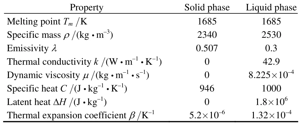
Table 1. Silicon’s physical properties

Table 2. Other material’s physical properties
Fig. 2 shows the argon gas flow path above the melt free surface and the oxygen concentration at the melt-crystal interface. Simulation result shows that a furnace with no heat shield has a higher oxygen concentration than that with a heat shield. The heat shield formed an efficient flow path for the argon. The flow speed is also increased. The flow speed in a classic argon streaming field is low, as shown in Fig. 2(a), and formed a relative stable argon atmosphere above the melt. With this design the evacuation speed of SiO is dramatically lowered and the oxygen concentration is accordingly increased.

Fig. 2. Distribution of argon flow and oxygen by different heat shields in Cz system
The right-angle heat shield can increase the flow speed of argon, and the melt surface is ventilated by the argon which will quickly move the evacuated SiO away. The SiO density is lowered in the argon atmosphere, so the evacuation speed of SiO is increased; the oxygen concentration is lowered accordingly, as shown in Fig. 2(b).To sum up, adding a heat shield in the thermal field is beneficial in lowering the oxygen concentration in the silicon crystal.
3.2 Comparison of three heat shield structures’ effect on melt’s thermal distribution and oxygen concentration at the melt-crystal interface
The above research shows that heat shields have significant benefit in lowering the oxygen concentration in the silicon crystal and different heat shield structures produce different effects. The following research is about the differences between the structures of a right-angle heat shield, an inclined heat shield and a composite heat shield.The right-angle heat shield has a different axial angle from the inclined heat shield; the impact on the ingot heat radiation is also different. A composite heat shield utilizing multiple materials has a different effect on crystallization rate and melt-crystal interface shape compared with an inclined heat shield utilizing a single material.
Fig. 3 shows the gas flow direction; melt temperature distribution and flow-function distribution. It indicates that with the right-angle heat shield, the melt free surface near the melt-crystal interface appears to be too cold and the temperature gradient of that area is increased while the Marangoni effect is strong. All these factors are not conducive to stabilize the melt-crystal interface.
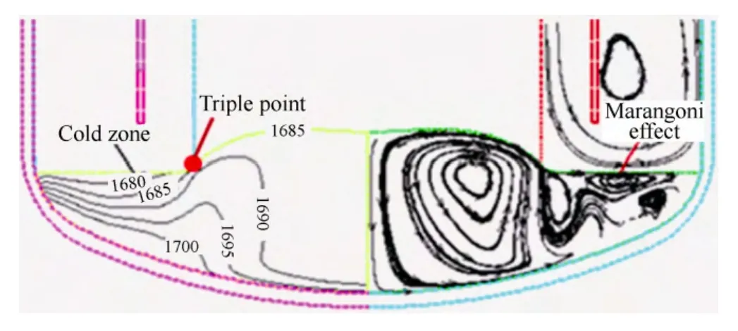
Fig. 3. Distribution of the temperature, stream traces and gas path with right-angle heat shield
The melt temperature and flow distribution of an inclined heat shield is shown in Fig. 4. Compared with right-angle heat shield, the lowest temperature on the melt free surface is 1686.68 K. The cold-zone around melt-crystal interface is eliminated. The average temperature between the outer reflector and the top shield insulator is lowered from the 1524 K to 1392 K which indicated the inclination of a heat shield is effective on the reduction of heat loss.
Fig. 5 shows the simulation of composite heat shield design. The gas flow path is a cone-shape between the outer side of heat shield and the inner side of the crucible. So the gas path is gradually narrowed. The average gas speed increased from 3 m/s to 6 m/s. This will speed up the transport of SiO evacuated from the melt surface and reduce the deposition of SiO on the crucible wall and on the outer side of the heat shield. Even if some SiO deposits around the corner of the melt flow, due to the narrow gap,the probability of SiO falling back into the melt is also lowered.

Fig. 4. Distribution of the temperature, stream traces and gas path with inclined heat shield
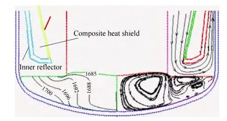
Fig. 5. Distribution of the temperature, stream traces and gas path with composite heat shield
Compared to the inclined heat shield, the composite heat shield is more flexible on the selection of raw materials.Select graphite types with different reflection rates on the inner and outer reflector can affect the temperature distribution and the shape of melt-crystal interface. Based on many experiments and simulation, using high reflection rate graphite on the inner reflector and low reflection graphite on the outer reflector to form the composite reflector would be a good choice. That’s because the low reflection rate graphite on the outer reflector will restrict the heat input while the high reflection rate graphite will absorb the excessive heat radiation from the crystal surface and reduce the heat reflection to the crystal. The heat inside the crystal can dismiss more quickly.
In a Cz-Si system, the growth process is in control of the melt-crystal interface. Therefore the stability of melt-crystal interface is of great importance to the growth process.Generally, it is easier to obtain good crystal quality with a flat interface shape[21–22]. Fig. 6 shows the interface shape deformation of 3 different heat shields. As shown in the figure, the most curved interface shape is formed on the right-angle heat shield. It will cause irregular segregation of solute and increase stress inside the crystal. Under some circumstances it causes dislocation even multi-crystalline silicon. The interface shape with the inclined heat shield is the flattest compared to the other two. But the average deformation already exceeds 25 mm more than the reference level. Simulation result shows the increased pulling speed can form a cold-zone around the melt free surface. In this system the maximum pulling rate with inclined heat shield is 0.6 mm/min while with the composite heat shield the maximum rate can be 1.0 mm/min.
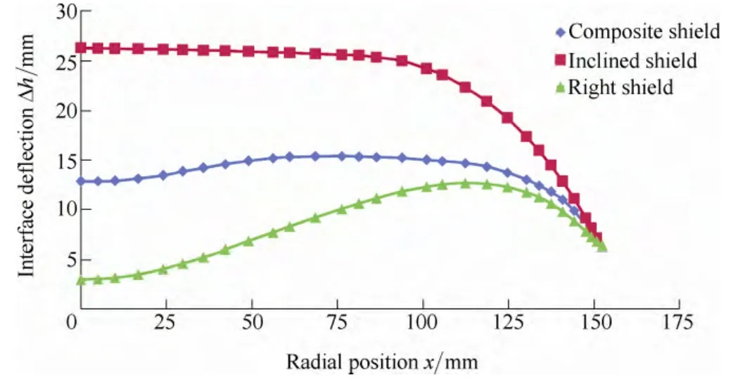
Fig. 6. Comparison of crystal-melt interface deflection with inclined and composite heat shield, respectively
The reason is that the crystallization rate depends on the inflow and outflow of heat at the melt-crystal interface, as shown in Eq. (10):

where Vsis the crystallization velocity,are the temperature gradients of the crystal front and the melt. To increase crystallization rate, the gradient of axial temperature along the crystallization front of the crystal should be increased or along the crystallization front of the melt decreased. That is, to increaseor decrease
Fig. 7 and Fig. 8 are the axial temperature distribution of crystal and melt with inclined composite heat shield design.From Fig. 7, the composite heat shield’s temperature gradient at the interfaceis larger than the gradient of the inclined type. Fig. 8 shows the composite type’s temperature gradient at the interface is close to that of the inclined type.According to Eq. (10) the composite heat shield’s crystallization rate is faster. So adopting a composite heat shield design will get a faster crystallization rate.

Fig. 7. Axial temperature distribution on the crystal with inclined type and composite type heat shield, respectively
Table 3 compares the heating power difference between different heat shield types. The types are no heat shield,right-angle heat shield, inclined heat shield and composite heat shield, while growing a Cz-Si ingot of φ300 mm up to 400 mm length. Conclusions from the table are, the most power consumption design is the inclined type and the least power consuming type is the composite. Adopting the composite heat shield structure can lower the monocrystalline production cost. Simulation shows that the oxygen concentration at the interface is very high while adopting the no heat shield design. That’s because with that structure the gas blow strength above the melt free surface was too small to evacuate the SiO and caused the oxygen concentration at the interface. As shown in Fig. 9, the oxygen concentration of the composite heat shield structure is the lowest among all the designs. Fig. 10 is a 3D sketch of the composite heat shield.

Fig. 8. Axial temperature distribution of the melt with inclined type and composite type heat shield, respectively

Table 3. Comparison of heating power under no heat shield,right-angle type, inclined type and composite type
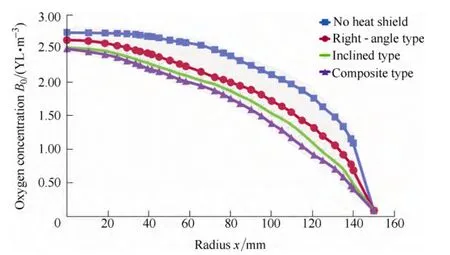
Fig. 9. Oxygen concentration at crystal-melt interface with no heat shield, right-angle, inclined and composite heat shield
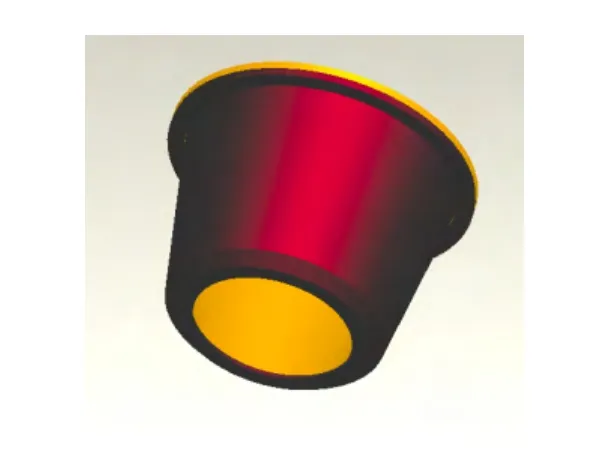
Fig. 10. Composite heat shield’s 3D illustration structure
Composite heat shield design can increase pulling rate and be more efficient. During experiment, actual melt-crystal interface shape acquired by Quick Pull Separation Method is shown in Fig. 11. Pulling parameters is set in accordance with those in the simulation. In the separation process, the pulling rate was separately set to 0.6 mm/min and 1.0 mm/min. The interface after the separation is believed to be the same with real phase change interface. The dots on the interface are formed by local viscosity of melt and crystal.

Fig. 11. Melt-crystal real interface shape in the composite heat shield system at different pulling rate of 0.6 mm/min (left) and 1.0 mm/min (right)
By the analysis of the interface shape, the simulation results show the conformity with that acquired in the experiment, as shown in Fig. 12.
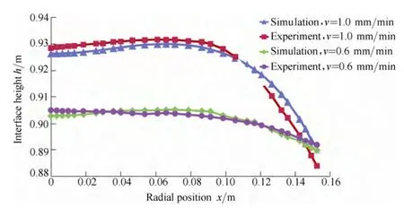
Fig. 12. Comparison of real melt-crystal interface and simulated interface under action of the composite heat shield
4 Conclusions
In a large Cz-Si thermal system, heat shield structure affects the temperature distribution of the melt and the evacuation of SiO and the oxygen concentration in the crystal. The numerical simulation result indicates the following.
(1) Compared with no heat shield design, the power consumption is improved by the right-angle heat shield structure. However, it has disadvantages on the evacuation of SiO and lower crystallization rate.
(2) The heat can be conserved by the inclined heat shield at the melt free surface. The temperature near the melt-crystal interface is stabilized. It is helpful to make the interface flat and growth process stability; but the design also lowers the heat-removal rate on the crystal ingot which works against a higher pulling rate.
(3) By the composite heat shield, the lateral length of the heat shield bottom side and the gas flow speed over the melt free surface are increased. It is beneficial for the evacuation of SiO, and then lowers the oxygen concentration at the melt-crystal interface and improves the crystal quality. The power consumption is lowered and the system pulling rate is increased. Actual melt-crystal interface shape acquired by Quick Pull Separation Method is compared with the simulation result. It shows the conformity which will provide a reference for the systematic production parameter design.
To sum up, it is ideal to adopt a composite heat shield for a large diameter mono-crystalline furnace. The drawback is that the coating on the inner and outer reflector of the composite heat shield is expensive. After taking the other advantages into consideration such as high pulling rate and low power consumption, it is still an optimal choice.
[1] CHENG Y K, CHIE G, BAU T D. Photovoltaic characteristics of silicon nanowire arrays synthesized by vapor–liquid–solid process[J]. Solar Energy Materials and Solar Cells, 2012, 25(1):154–157.
[2] LI Zaoyang, LIU Lijun, MA Wencheng, et al. Effects of argon flow on heat transfer in a directional solidification process for quasi-single crystalline silicon ingot for high-efficiency solar cells[J].Journal of Crystal Growth, 2012, 18(3): 298–303.
[3] MA Wencheng, ZHONG Genxiang, SUN Lei, et al. Influence of an insulation partition on a seeded directional solidification process for quasi-single crystalline silicon ingot for high-efficiency solar cells[J].Solar Energy Materials and Solar Cells, 2012, 76(2): 231–238.
[4] CHEN J C, TENG Y Y, WUN W T, et al. Numerical simulation of oxygen transport during the Cz silicon crystal growth process[J].Journal of Crystal Growth, 2011, 318(1): 318–323.
[5] TIAN Daxi, YANG Deren, MA Xiangyang, et al. Crystal growth and oxygen precipitation behavior of 300mm nitrogen-doped Czochralski silicon[J]. Journal of Crystal Growth, 2006, 292(2):257–259.
[6] ZHANG Yuliang, LI Yi, CUI Baoling, et al. Numerical simulation and analysis of solid-liquid two-phase flow in centrifugal pump[J].Chinese Journal of Mechanical Engineering, 2013, 26(1): 53–58.
[7] YU B, LIU C, HOU P X, et al. Bulk synthesis of large diameter semiconducting single-walled carbon nanotubes by oxygen-assisted floating catalyst chemical vapor deposition[J]. Journal of the American Chemical Society, 2011, 25(14): 5232–5235.
[8] GOLDSTEIN R V, MEZHENNYI M V, MIL’VIDSKII M G, et al.Experimental and theoretical investigation of formation of the oxygen-containing precipitate-dislocation loop system in silicon[J].Physics of the Solid State, 2011, 11(3): 527–538.
[9] FREDERIC M, SHIN-ICHI N. Solution growth of SiC from silicon melts: Influence of the alternative magnetic field on fluid dynamics[J]. Journal of Crystal Growth, 2011, 318(1): 385–388.
[10] LIU Lijun, KOICHI K. Effects of crystal rotation rate on the melt-crystal interface of a Cz-Si crystal growth in a transverse magnetic field[J]. Journal of Crystal Growth, 2008, 310(2):306–312.
[11] ZHUANG Weimin, WANG Shiwen, BALINT D, et al. Crystal plasticity finite element process modeling for hydro-formin mircro-tubular components[J]. Chinese Journal of Mechanical Engineering, 2011, 24(2): 1–6.
[12] TENG Y Y, CHEN J C, LU C W, et al. Effects of the furnace pressure on oxygen and silicon oxide distributions during the growth of multicrystalline silicon ingots by the directional solidification process[J]. Journal of Crystal Growth, 2011, 318(1): 224–229.
[13] SU Wenjia, ZUO Ran, KIRILL M, et al. Optimization of crystal growth by changes of flow guide, radiation shield and sidewall insulation in Cz Si furnace[J]. Journal of Crystal Growth, 2010,312(4): 495.
[14] REN Binyan, ZHAO Long, FU Hongbo, et al. Effects of a heat shield on pull speed and oxygen concentration in a φ 200mm Cz Si[J]. Chinese Journal of Semiconductors, 2005, 26(9): 21–24.
[15] TENG Y Y, CHEN J C, HUANG C C, et al. Numerical investigation of the effect of heat shield shape on the oxygen impurity distribution at the crystal–melt interface during the process of Czochralski silicon crystal growth[J]. Journal of Crystal Growth,2012, 352(1): 167–172.
[16] MIN Naiben. Physical fundamentals of crystal growth[M]. Shanghai:Shanghai Science Technology, 1982. (in Chinese)
[17] MULLER G. Review: the czochralski method—where we are 90 years after Jan Czochralski’s invention[J]. Crystal Research and Technology, 2007, 42(12): 1150–1161.
[18] TAKAO T, MASAKI K, CHEN J J. A global analysis of heat transfer in the CZ crystal growth of oxide: recent developments in the model[J]. Journal of Crystal Growth, 2007, 57(2): 150–155.
[19] ZHANG Jing, LIU Ding, ZHAO Yue, et al. Study on crowning growth in Czochralski silicon monocrystal based on the numerical simulation of finite element and parameters control[J]. Journal of Synthetic Crystals, 2013, 42(1): 58–64. (in Chinese)
[20] JIANG Lei, LIU Ding, ZHAO Yue, et al. Study on solid-liquid interface morphology simulation method and control parameters of Cz-Si under multi—stream coupled environment[J]. Journal of Synthetic Crystals, 2012, 41(6): 34–39.
[21] SU M F, OLSSON, REINKE H, et al. Realization of optimal bandgaps in solid-solid, solid-air, and hybrid solid-air-solid phononic crystal slabs[J]. Applied Physics Letters, 2011, 98(6):061912.
[22] LIU Xin, LIU Lijun, LI Zaoyang. Prediction of melt-crystal interface shape and melt convection in a large-scale[J]. ECS Transactions, 2009, 18(1): 983–988.
 Chinese Journal of Mechanical Engineering2014年3期
- Chinese Journal of Mechanical Engineering的其它文章
- Theoretical Analysis and Experimental Verification on Valve-less Piezoelectric Pump with Hemisphere-segment Bluff-body
- Carbody Structural Lightweighting Based on Implicit Parameterized Model
- Prediction-based Manufacturing Center Self-adaptive Demand Side Energy Optimization in Cyber Physical Systems
- Effectiveness of a Passive-active Vibration Isolation System with Actuator Constraints
- Numerical Simulation and Analysis of Power Consumption and Metzner-Otto Constant for Impeller of 6PBT
- Proceeding of Human Exoskeleton Technology and Discussions on Future Research