
Design of car reverse anti- collision warningsystem based on AT89S52
2015-03-09 03:32YangshanTANGLinaGEDaohuaIAPeifeiYANG
机床与液压 2015年6期
Yang-shan TANG,Li-na GE,Dao-hua X IA,Pei-fei YANG
(1 Automobile& Transportation College,Liaoning University of Technology,Jinzhou 121001,China)
(2 ZhongDing Cushion Technologies Company Limited in Anhui Province,Anhui242300,China)
Design of car reverse anti- collision warningsystem based on AT89S52
Yang-shan TANG1*,Li-na GE1,Dao-hua X IA1,Pei-fei YANG2
(1Automobile& Transportation College,Liaoning University of Technology,Jinzhou 121001,China)
(2ZhongDing Cushion Technologies Company Limited in Anhui Province,Anhui242300,China)
In order to reduce the car scraping collision accidents caused by bad“rear view”when reversing,a car reverse anti-collision warning system is designed.This system takes AT89S52 single chip as themain control unit,and itadopts the HC-SR04 ultrasonic rangingmodule to realize the non-contact distancemeasurement.On the basis ofmatching the hardware,we designed the circuit and software,and carried out the test experiment,analyzed the ranging error.This system detection range can be 2~400 cm,ranging accuracy is up to 3mm,and it can satisfy the requirement of the early warning of a car when reversing in the narrow space.
Microcontroller,Anti-collision warning system,Ultrasonic
*Corresponding author:Yang-shan TANG,Professor.
E-mail:tysby_jz@163.com
1 In troduction
In recent years,with the rapid development of automobile industry and the continuous improvement of people’s living standard,the amount of automobiles increases rapidly in our country,which caused public places such as streets,parking lots,garages and other public places become more and more crowded,when reversing in the narrow place,the driver should not only look forward,but also look back,with little carelessness,an automobile tail scraping collision accident will happen[1].Related survey data statistics show that about15%of the reverse scraping collision accidentswere due to bad rear sight when reversing.Car reversing radar can use voice promptand distance displaying to alert driver the obstacles of automobile tail,it is convenient for drivers to back cars,but the detection range of back-draft radar on the currentmarket is shorter and the precision is not high[2],so they can’t advance the time for the driver to provide a larger reaction time,and they also have difficulty in helping the driver stop safety effectively within a small space.
In view of the above-mentioned facts,a new type of car reversing anti-collision warning system which has wider detection range and highermeasuring precision was designed in this paper.The whole system has the functions of distance display,light and sound alarm.
2 U ltrasonic ranging m odu les
The ultrasound refers to the waves with more than 20 kHz vibration frequency.As a kind of special sound wave,ultrasound has the characteristics of good direction,small attenuation,good penetration and reflection ability,etc.The underlying principle of ultrasonic ranging is:ultrasonic generator sends ultrasonic signals at a certainmoment,and the ultrasonic signals are reflected back after encountering obstacles in air,and then the echo signal is received by ultrasonic receiver[1].As long as we measure the time from launching ultrasonic signal to receiving echo signal,we can calculate the distance between obstacles to sound source,namely:

In the formula:d is thedistance between obstacles to sound source,s is the journey that ultrasonic wave goes there and back,c is the speed of ultrasonic in air,t is the time from launching ultrasonic signal to receiving the echo signal.
The HC-SR04 ultrasonic rangingmodule which this system adopts has relatively stable ranging performance,it has a highermeasurement accuracy,it can achieve the function of2-400 cm non-contact distance measurement,its ranging accuracy is up to 3 mm and comparable to foreign ultrasonic rangingmodule,such as SRF05,SRF02 and so on[3].Fig.1 is the physical figure of HC-SR04 ultrasonic ranging module,including ultrasonic transceiver and related control circuit.
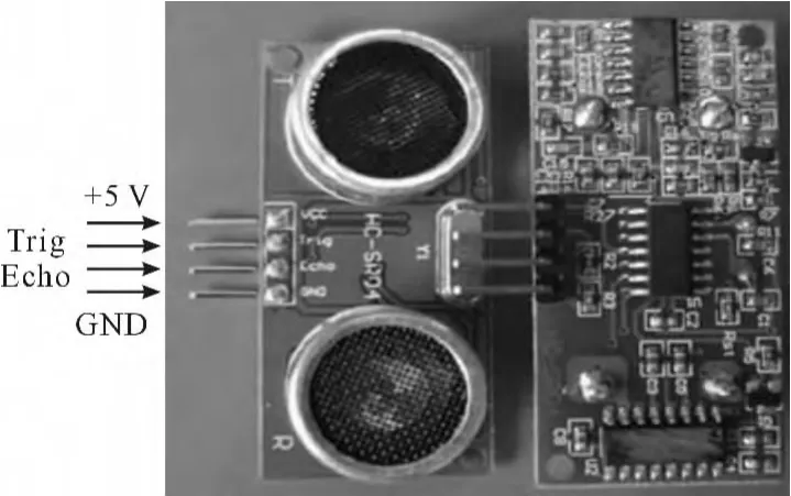
Fig.1 Physical figure o f HC-SR04 u ltrasonic ranging m odu le
2.1 The basic operation principle
Use the Trig mouth to trigger range,the signal of high level signal to 10 ormore us is given.
The internal HC-SR04 automatically gives out8 periodic levels with 40 kHz,and automatically detects whether there is a echo signal;
If echo signal dose exist,a high levelwill be output by Echomouth,the duration of high level is the time from launch ultrasonic to return it.Therefore,according to formula(1),the measuring distance=(the duration of high level* sound velocity)/2.
2.2 Themain technical parameters
Themain technical parameters of the HC-SR04 ultrasonic rangingmodule is shown in Table 1.
2.3 The distance sequence diagram
As shown in Fig.2,we only need to provide a trigger pulse signalwhich is greater than or equal to 10us from Trigmouth,the internal HC-SR04 will automatically send outeight squarewaves of40 kHz and detect whether there is a echo signal.If HC-SR04 detects a echo signal,then a echo signal is output.Therefore,you can wait for the output of high level by Echo mouth,once it output the Echo signal,then open timer timing immediately,when the Echo turns into low electricity,it will shut down timer immediately,then read the value of the timer,this value is the time from launch ultrasonic to return it,according to the equation(1)to calculate the distancemeasurement.

Tab le 1 The m ain technical param eters of the HCSR04 ultrasonic ranging m odu le
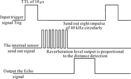
Fig.2 Ranging sequence d iag ram o f u ltrasonic ranging m odu le
3 The circuit design of hardware system
The overall structure of the system is shown in Fig.3,which mainly composes 3 parts-the main control unit,the ultrasonic rangingmodule and alarm display module,and it is concretely divided into single chip microcomputer control circuit,ultrasonic transmitting and receiving circuit,digital tube display circuit,indicator light and buzzer alarm circuit and other parts.AT89S52 single-chip microcomputer is the core component of the whole system,it is used to coordinate and control each part of the circuit work[2];Ultra-sonic ranging module adopts HC-SR04 transmit-receive one-piece ultrasonic ranging sensors,itsworking frequency is 40 kHz.Digital tube display module is used to show measure distance;Indicator and buzzer alarm module are used to remind the driver the danger level at this time.
3.1 Design of a single chipmicrocomputerminimum system
The core component of themain control unit system adopts the AT89S52 single chip microcomputer which was produced by ATMEL Company of US.Some car reversing radar system uses AT89C51 and AT89C52 chip as main units[4-5].And this paper uses the AT89S52,which is kind of low power consumption,high performance CMOS8microcontroller,which has8 Kb in system programmable Flashmemory;it can provide faster storage and computing speed and improve the precision and the real-time performance of collision avoidance system effectively.AT89S52 devices use dual-in-line package(DIP)form which has 40 pins.In 40 pins,there are two pins dedicated to the pin ofmain power supply,two external crystals pins,four control pins and thirty-two I/O pins.AT89S52 has the following functions:Flash memory with 8 Kb,datamemory RAM with 256B,program memory ROM with 4 Kb,four 8-bit programmable I/O ports,watchdog timer,two data pointers,three 16-bit timer/counters,one level2 interrupt structure of 6 vector,a full-duplex asynchronous serial communication interface,piece inside crystals timely clock circuit.
Single chip microcomputer minimum system is the most basic circuit for the single-chip computer and its peripherals to run.Single chip microcomputer minimum system mainly consists of four parts,power supply circuit,crystals circuit,reset circuit and program download circuit.

Fig.3 General structure d iag ram o f reverse w arning system
3.1.1 Power supply circuit
Power supply circuit is primarily responsible for providing a stable power supply voltage for the main control unit,ensuring the normal operation of the system.It is responsible for distributing the 5 V supply voltage power which is applied between VCC and VSS pins to the single-chip microcomputer of each functional circuit.
3.1.2 Crystal oscillation circuit and reset circuit
Crystal oscillation circuit,or clock pulse generator,is the time benchmark of single chip microcomputer,and determines its working speed and efficiency and produces the required clock pulse and timing signal of the whole inside chip for normal operation of each functional circuit.One of the most common circuit connection methods is an external crystal oscillator XTAL and two external capacitors C1 and C2,grounded between XTAL1 and XTAL2 pins.Crystal’s circuit connection type is shown in Fig.4.
Reset circuit is used to determinework starting state of single chip microcomputer,such as initializing the state ofmachine to empty state,and thenmaking single chip microcomputer execute a program from the very beginning.The power on resetand hand resetare commonly used,this design uses the hand reset,and its circuit is shown in Fig.4.As long as you press the RESET button,the MCU will turn to RESET state.
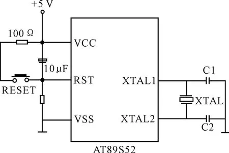
Fig.4 Crystal oscillation circuit and reset circuit
3.1.3 Program download circuit
The program download circuit selects MAX232 as chip,which was produced by MAXIM Company.The role of MAX232 is to turn the output TTL level from chip microcontroller into 232 levels which can be received by PC,or to convert the output 232 level from PC into TTL level which can be received by single chip microcomputer.MAX232 chip adopts single power supply of+5 V,only a few external capacitances can finish the transformation from TTL to RS-232 levels[6].The typical RS-232 serial communication circuit is shown in figure 5,T1in and R1outare connected respectively with P3.1 and P3.2 pins of single chip microcomputer,it can achieve level conversion between MCU and PC,finally complete the asynchronous serial communication between the two[3].
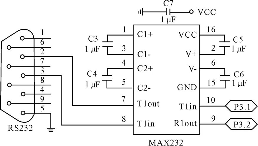
Fig.5 Serial comm unication circuit
3.2 Ultrasonic emission circuit and receiving circuit
Ultrasonic transmission circuit is shown in Fig.6.Ultrasonic transmission circuit ismainly composed by the ultrasonic transducer and the reverser 74ALS04,etc.
Ultrasonic receiving circuit is shown in Fig.7.The ultrasonic receiving circuit is mainly composed of ultrasonic receiving probe part,signal amplifying circuit and waveform conversion circuit parts.

Fig.6 U ltrasonic transm itting circuit

Fig.7 The u ltrasonic receiving circuit
3.3 Digital tube display circuit
Distance display part adopts“four-in-one”shared anode digital tube to display,and a dynamic scanning way to drive the LED interface circuit of digital tube.The circuit connection is shown in Fig.8.

Fig.8 Digital tube disp lay circuit
3.4 Alarm circuit
As shown in Fig.9 and Fig.10,system alarm part adopts the combination of LED lightand buzzer alarm.LED warning light signs are divided into red,yellow,and green three colors,which are used to provide light alarm.Alarm buzzer can be divided into prolonged sound and short sound,and it is used to provide sound alarm.When backing distance is larger than 2 m,LED indicator gives a green light,buzzer dose not ring;When backing distance is between 1-2m,LED indicator gives a yellow light,the buzzer gives a long sound alarm at the same time;When backing distance is less than 1 m,the LED indicator gives a red light,the buzzer gives a shortness of alarm at the same time.

Fig.9 Light alarm circuit

Fig.10 Buzzer alarm circuit
4 The software design
System software part uses C programming language to write,and conductsmodular design,mainly including the main program,timer interrupt subroutine,external interrupt subroutine and alarm display subroutine,etc.The design of the application process is shown in Fig.11.
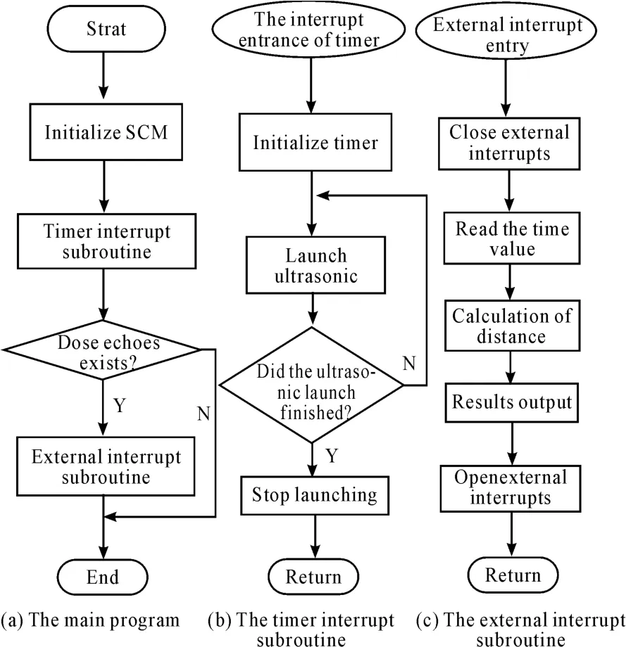
Fig.11 Programm er flow chart
5 Analysis of the experim enting result
Through many real vehicle tests,we found that HCSR04 ultrasonic ranging module realizes accurate range within the scope of30-400 cm,under the condition of random error is eliminated;themaximum error is less than 2%.Compared with other reversing radar,this paper design the back-draft radar and its measuring distance at least increased by more than 60%and the measurement precision has reached the millimeter,it canmeet the demand of the driver’s car reversing.The existence of the error ismainly affected by the influence of temperature ofmeasurement environment;therefore,temperature compensation measures should be used in the practical application to improve the range accuracy of results.The experimental results are shown in Table 2.
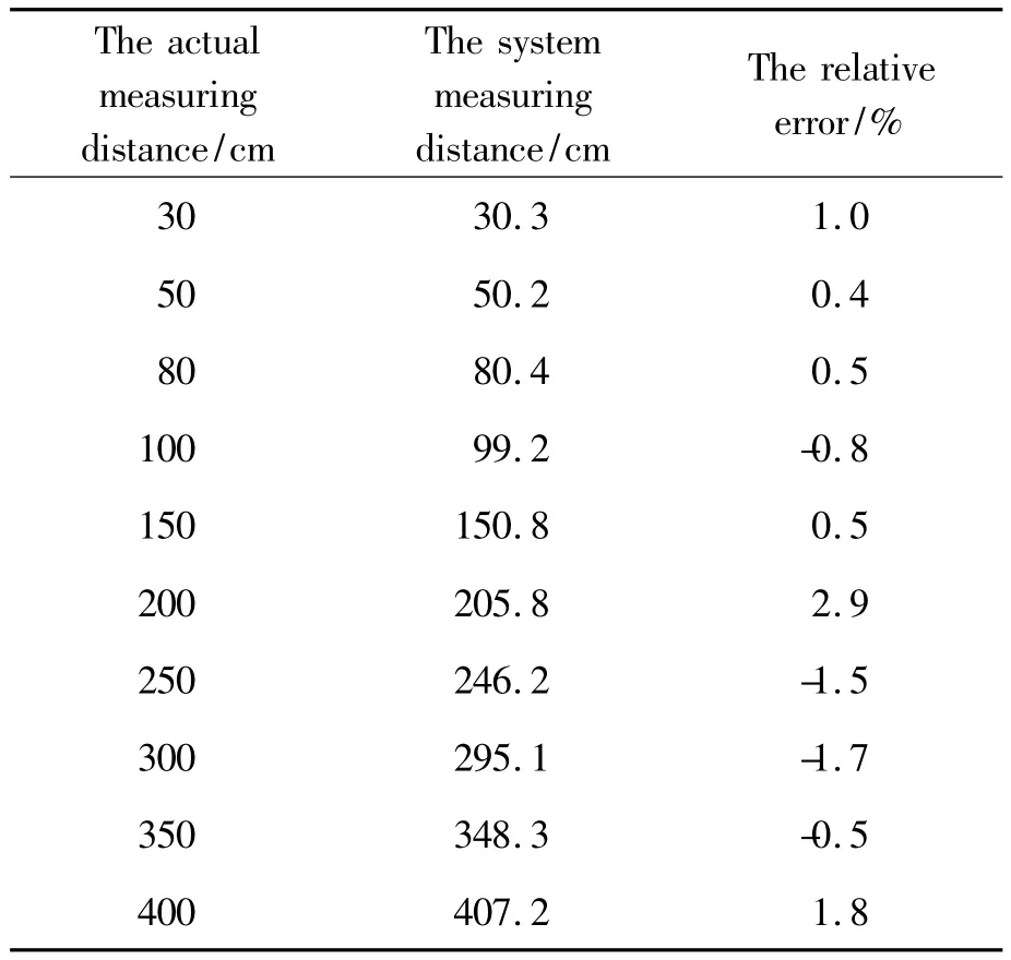
Tab le 2 The ranging experim en tal resu lt
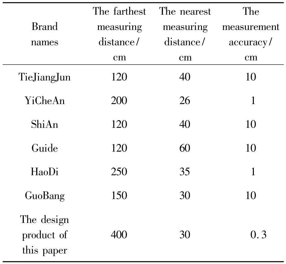
Tab le 3 The m ain perform ance com parative experim en tal resu lts o f design p roduct and o ther brand reversing radar
6 Summ aries
In this paper,the design of automobile reverse collision warning system takes AT89S52 single chip microcomputer as main control chip,adopts the HC-SR04 ultrasonic rangingmodule to realize the non-contact distancemeasurement.Experimental results show that the system improves the measurement range and measurement accuracy and achieves expected effect of anti-collision alarm.The system has reasonable design,aswell as good market application value.
Acknow ledgem ents
This paper is supported by Program for Liaoning Excellent Talents in University(No.LJQ2012058).
[1]Zhu Lina.Study of Ultrasound Distance-Measurement Automobile-Reversing Rader Based on Microcontroller[J].Microcomputer Information,2007,23(23):110-111,73.
[2]Su Lin.Design of Ultrasonic Rangefinder Based on HCSR04[J].Science & Technology Information,2012(3):25.
[3]Wang Xingwei.The Research of Automobile’s Vertical Anti-Collision Warning technology based on DSP[D].Zibo:Dissertation for the Master’s Degree in Engineering of Shan Dong University of Technology,2011,6.
[4]Han Boqi.The research of Parking Distance Control System[D].Harbin:Harbin Institute of Technology,2006.
[5]Wu Lizhen,ZENG Yingshen.Design ofmulti-ultrasonic signal fusion system based on AT89C52[J].Microcomputer Information,2006,22(11):86-89.
[6]Wu Qiong,FENGWeizhong,MAWenjie.Design and Implementation of the Automobile Reversing Radar System[J].Modern Electronics Technique,2009,5:1.
[7]Wang Xiao Li.Technical Study ofWireless Communication Module Based on nRF905 for Vehicle Anticollision.Advances in Information Sciences and Service Sciences,2013,6(5):749-757.
[8]Xinlu Ma,Yeren Liu,Jiang Cheng.Analytic and Heuristic Methods of Collision Detection for Curve-Moving Vehicle Based on Cooperative Collision Warning System[J].Journal of Convergence Information Technology,2013,2(8):244-253.
汽车倒车防撞的AT89S52微控制报警系统
唐阳山1*,葛丽娜1,夏道华1,杨培菲2
1.辽宁工业大学汽车与交通工程学院,辽宁锦州 121001
2.安徽中鼎减震橡胶技术有限公司,安徽宣城 242300
汽车倒车防撞预警系统可以有效降低汽车倒车时发生刮擦碰撞事故的几率。该系统以AT89S52微处理器为主控制器,采用HC-SR04超声波测距传感器实现倒车时后方空间的测距,在主控单元设计和测距模块设计的基础上,进行了数据通信电路设计,并设计了软件系统,最后进行了测试实验。经过实验数据分析,系统探测距离范围在2~400 cm,测距精度达到3 mm。结果表明:该系统测距范围较大,测距精度不会造成对汽车的损害,能够满足汽车在狭小空间内的倒车预警要求。
微控制器;报警防撞系统;超声波传感器
10.3969/j.issn.1001-3881.2015.06.007 Document code:A
U461.91
16 September 2014;revised 12 November 2014;accepted 21 December 2014
猜你喜欢
新少年(2022年3期)2022-03-17
共产党员·上(2020年6期)2020-07-04
共产党员(辽宁)(2020年11期)2020-07-03
科学(2020年3期)2020-01-06
学与玩(2018年5期)2019-01-21
小哥白尼(趣味科学)(2018年12期)2018-12-18
汽车工程师(2018年1期)2018-07-13
电子制作(2017年7期)2017-06-05
中国公路(2017年13期)2017-02-06
民用飞机设计与研究(2015年3期)2015-12-07
- 机床与液压的其它文章
- Time constant of a hydraulic servo valve withdynamic pressure feedback
- Research on fault diagnosis and fault toleranttechnology of IGBT in active power filters
- A new test generation algorithm fornon- robust path delay faults
- Radial fretting character research ofthe shaft-hub of compress impellerbased on virtual orthogonal experiment
- Custom implant design for patients withmandible defects based on rapid prototyping
- Study on high precision cymometer ofmechanical vibration