
Time constant of a hydraulic servo valve withdynamic pressure feedback
2015-03-09 03:32LeiZHANGHongzhouJIANG
机床与液压 2015年6期
Lei ZHANG,Hong-zhou JIANG
(1 School of Physics and Electronics,Henan University,Kaifeng 475001,China)
(2 School of Mechatronics Engineering,Harbin Institute of Technology,Harbin 150001,China)
Time constant of a hydraulic servo valve withdynamic pressure feedback
Lei ZHANG1*,Hong-zhou JIANG2
(1School of Physics and Electronics,Henan University,Kaifeng 475001,China)
(2School of Mechatronics Engineering,Harbin Institute of Technology,Harbin 150001,China)
Dynamic pressure feedback(DPF)technology is usually used in a hydraulic servo system to improve its response characteristics.Themost reliable way to realize the feedback is to integrate amechanical DPF device in a flow control servo valve.However,as a key parameter,the time constant is usually big different between the desired and actual valve if the valve has been designed by traditionalmethod.We analyze this reason which is mainly caused by thewrong assumption thatoil jetting from feedback nozzles is in the turbulent flow region.Based on the theoretical analysis and experimental tests,it has been confirmed that the fluid flow is indeed in laminar flow region.Therefore,a new method to evaluate the time constant could be obtained,which will be very useful for the design of a DPF device.
Servo valve,Dynamic pressure feedback,Time constant,Laminar flow,Design method
*Corresponding author:Lei ZHANG,Associate Professor.
E-mail:dr.zhanglei@126.com
1 In troduction
Electro-hydraulic servo valve is the core element in an electrohydraulic servo control system.Basic type is a flow control servovalve.It is very popular in position servo control.When amassive plant is controlled,the hydraulic natural frequency is relatively low [1].Damping ratio must be increased to achieve a quick response.Although a complex digital compensator could be designed to implement demands,the real effectmainly depends on the quality of feedback sensors.Reliability of this electrical system is not usually as high asmechanical system.In some critical applications,such as thrust vector servo control of carrier rocket,reliability becomes themost important.Therefore,dynamic pressure feedback(DPF)servovalve is designed to increase the damping ratio[2].The benefits of pressure feedback could be realized as damping for a resonant load,but statically the system retains the high resolution and stiffness characteristics obtained with a flow control servovalve[3].Even so,the result of traditional formulas is not satisfied by the experiments when the time constant of the core DPF device is evaluated,which is the key parameter for the design of DPF servovalve.Using the obtained time constant for design willmake actual dynamic characteristic large difference with the expected behavior.This might even lead to system unstable sometimes[4].So,newmethod which is accordancewith experiments should be studied to instruct the design of DPF device directly in the real industrial applications.
This paper is to explore a new way to compute time constantwhich could help the design of DPF device.In traditional consideration,oil jetting from nozzles of DPF device is usually considered as turbulent flow.This appeared in the reference[3],in which time constantwas described as a changeable parameterwith load pressure.Based on this assumption,the time constant is usually about three times greater than that measured through experiment[5].But,based on the analysis in this paper,the flow status of oil is actually in laminar flow region.And this condition will derive the correct evaluation of time constant and it will be consistentwith that of the experiment results.
Chapter two introduces the component and structure of DPF valve.Chapter three shows a traditionalmathematicsmodel for the DPF device.The revised model will be deduced in chapter four.Chapter five validates themodel by comparing the simulation results and experimental data.Finally,we concluded the advantageous of thismethod in a real engineering application.
2 Dynam ic p ressure feedback valve
DPF valve is composed of DPF device and a normal flow control valve.The DPF device is a hydraulic high pass filter which is made of capacitance piston,spring,and feedback nozzles,as shown in Fig.1.Capacitance piston will stop at somewhere when the load pressures of the two chambers are constant.It could adjust the position according to the change of differential load pressure.The reciprocating motion of piston will push oil jetting from the feedback nozzles.This could generate a feedback torque acting on flapper and armature.
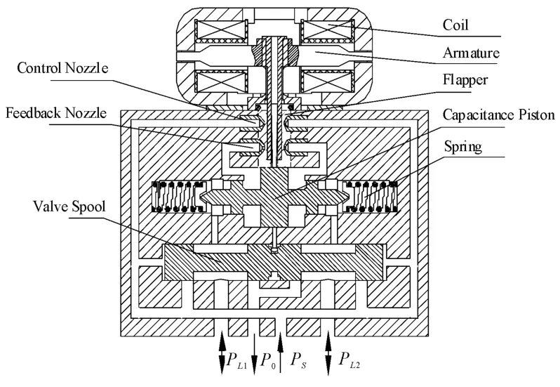
Fig.1 Com ponent and structure o f a DPF valve
The schematic diagram of the DPF device is shown in Fig.2.A traditional opinion considers that oil jetting from nozzle of DPF device is in the turbulent flow region.Therefore,we will firstly deduce the transfer function of DPF device based on this assumption.
3 Traditionalm odel
Ifwe assume oil jetting from nozzles of DPF device is in the turbulent flow region and flapper is located on the left side at this time,the flow continuity equation[6]of the capacitance piston on the left side could be written as follows:
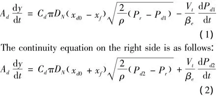
Where,Cdis flapper-nozzle discharge coefficient,DNis nozzle diameter,xd0is flapper to nozzle distance at null,xfis displacement of flapper,Pris oil return pressure,Pd1is pressure of left chamber of capacitance piston,Pd2is pressure of right chamber of capacitance piston,Vtis volume of capacitance piston cavity,βeis bulk modulus of hydraulic oil,Adis effective piston area,ρis density of hydraulic fluid,and y is the piston position.
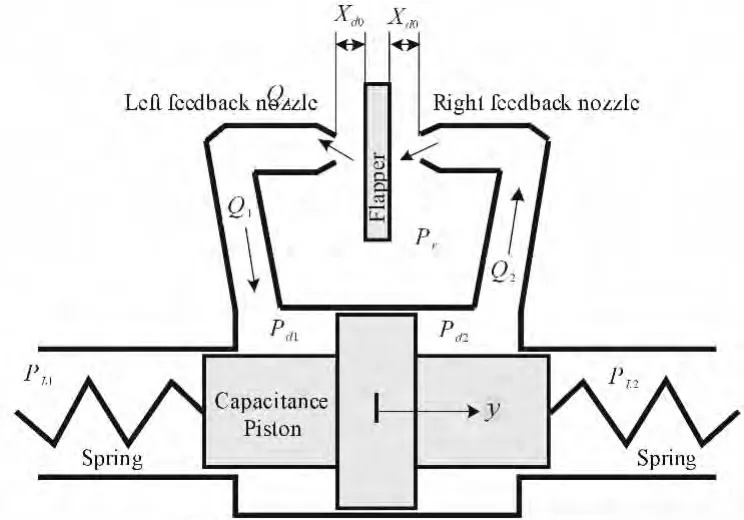
Fig.2 Schem atic d iagram o f a DPF device
The dynamics for capacitance piston[6]could be obtained through the following equation:

Where,PL1is the left side pressure of capacitance piston,PL2is the right side pressure of capacitance piston,k is spring constant,bcis viscous damping coefficient,and m ismass of capacitance piston,and ALis effective action area of load pressure.
In order to obtain the transfer function,we consider that the flapper is at its neutral position and omit the term of volume change on the pressure derivative in equation(1)and(2).Therefore,it yields:
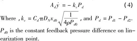
If the damping force and inertial force are ignored in(3),one could obtain the following equation:

However,the time constant deduced by equations(7)and(8)is usually three times greater than the actual value measured by experiments.So,the assumption that the oil jetting from nozzles of DPF device is in turbulent flow region must not be correct.The computed time constant can not be used to instruct the design of DPF valve.
Although control nozzle always jets turbulent flow due to the fact that large pressure difference exists in the nozzle and oil usually flows very fast,the feedback nozzle is in a different situation.Pressure difference between two sides of the nozzle is relatively small,and the oil flow quantity is small as well.Therefore,the Reynolds number of flow is very small and the oil flow is in the laminar flow region.Based on this deduction,amodified model could be proposed to evaluate the time constant.
4 Modified model
Flow from feedback nozzle is under low Reynolds number.The quantity of oil flow [7]is

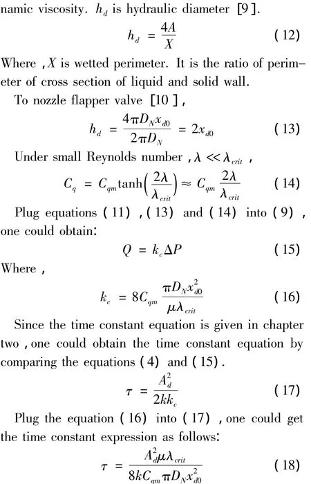
From next chapter,we can find that(18)is very appropriate for DPF valve design.And it is very consistentwith that of experimental data.
5 Simu lation and experimen t test
Time constant of DPF device is defined in(6).We use AMESim to build the nonlinear model which reflects relationship of PLand Pd.Mathematical equations in this AMESim model are followed the contents of chapter four.So,we can compare the simulation resultswith the experimental results to validate correction of the deduction of chapter four.
AMESim is a unified platform ofmodeling and simulation software used in multidisciplinary field[11].It not only has intelligent solver and rich module libraries,but also provides perfect tools to analyze and optimize system[12].
The DPF device described in AMESim is shown in Fig.3.The load pressure difference is as input signal acting on the capacitance piston.The pressure drives the piston to move and form a mass-spring-damping system.The dynamics of piston and flow rate are gov-erned by the internal equations of AMESim,which could be found in themanuals.

Fig.3 Skeleton diagram o f the DPF device.
Oil pushed out from the chamber of DPF devicewill flow into themodel of flapper nozzle valve.Thismodel contains the hidden equations from(9)to(16).It reflects the characteristics of feedback nozzle.Therefore,the pressure difference of the inlet ports of the two nozzle valve models is the feedback pressure difference,i.e.,Pd.
By using the analysis tool of frequency response,one could obtain the characteristics of high pass filter of the DPF device.The input parameter is PLand the output parameter is Pd.Once the frequency response could be obtained,the time constant of the filter will be evaluated.
Parameters in the simulation model are set according to a series ofmanufactured DPF valve[13].The parameters are divided in two groups,as shown in Table 1.The only difference of these two groups is the spring constant.

Tab le 1 Param eters o f tw o valves
We can use equation(7),the traditionalmethod to evaluate the time constants of the two valves.And then,the proposed new method,i.e.,equation(18),is used to obtain the corresponding time constants.On the other hand,AMESim simulationmodels were used to obtain the time constants.All the time constant results including the one measured from the experiments are shown in Table 2.

Tab le 2 Tim e Constant o f Tw o Valves
From Table 2,one could find that the time constant formula,i.e.,equation(18),could provide a good estimation and the precondition is quite right about that flow jetting from feedback nozzle is in laminar flow region.
6 App lication
Time constantτwill influence the dynamic performance of hydraulic system.Open loop transfer function from valve input signal to load flow could bewritten as follows
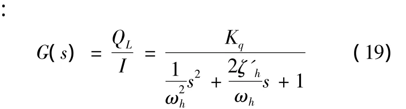
Where,QLis servovalve flow to the load;I is differential current input to torque motor of servovalve;Kqis flow gain;ωhis natural frequency of servovalve;ζ'his damping ratio,which has been increased by DPF device for improving system performance.
The damping ratioζ'hwill get increased with the increase ofτ.Damping capacity is relative good ifτis big.However,a big value ofτwill increase the interference error by external force.So,a properτ should satisfy the demands of system frequency response,transient response,system stiffness and precision.Generally speaking,in order to improve response performance and suppress disturbance,τis usually in the following range[3]:

Where,ωnis resonant frequency of the hydraulic pow-er system.
Since we obtained a precise formula to compute time constant of DPF device,we could use it to design a proper DPF valve.After setting up dimensions of nozzle and flapper by experience,dimensions of capacitance piston and spring constant could be computed based on constrain relationship of the time constant formula(18).
7 Conclusion
In this paper,we analyze the defects of traditional method to resolve time constant of DPF device.Oil jetting from feedback nozzle is in laminar flow region.Based on this deduction,a new formula of time constant is proposed.Experimental results confirmed that this formula could provide better results of time constant.Therefore,it could be used as DPF device design tool,which is significant to the real industrial applications.
[1]Gray,Samuel A.Dynamic pressure feedback servo valve[P].U.S.Patent3042005,July 3,1962.
[2]Welch T R.The Use of Derivative Pressure Feedback in High Performance Hydraulic Servomechanisms[Z].Transactions of the ASME,No 8,February,1962.
[3]Thayer W J.Transfer functions for MOOG servovalves[Z].Technical Bulletin 103.New York:MOOG Inc.,1965.
[4]Jelali M,Kroll A.Hydraulic Servo-Systems:Modelling,I-dentification,and Control[M].London:Springer,2003.
[5]Zhao Jiangbo.Test Method for Dynamic Pressure Feedback Servo Valve[J].Acta Aeronautica Et Astronautica Sinica,2009(10):251-258.
[6]Merritt,Herbert E,Hydraulic Control Systems[M].New York:Wiley,1967.
[7]Guillon M.Hydraulic servo systems:analysis and design[J].Butterworths,1969
[8]Morse A C.Electrohydraulic Servomechanisms.McGraw Hill[M].New York:[S.l.],1963.
[9]Sheng Jingchao,Hydraulic Mechanics[M].BeiJing:China Machine Press,1980.
[10]McCLOY D,MARTIN H.Control of Fluid Power:Analysis and design[M].Ellis Horwood Limited,1980.
[11]LMS,LMS Imagine Lab AMESim Solution Guide.LMS International.Belgium.http://www.lmsintl.com/
[12]Fu Y L,Qi X Y.System Modeling and Simulation Based on AMESim[D].Beijing:Beijing University of Aeronautics&Astronautics Press,2006.
[13]Chen Zuxi.Research on Dynamic Feedback of Servo Valve and Test Method[D].Harbin:Harbin Institute of Technology,2009.
动压反馈伺服阀时间常数计算方法
张 镭1*,姜洪洲2
1.河南大学物理与电子学院,河南 开封 475001
2.哈尔滨工业大学机电学院,哈尔滨 150001
动压反馈技术应用于喷嘴挡板伺服阀中可以显著改善其响应特性。在伺服阀中实现动压反馈最可靠的方法是在其中增加一个动压反馈装置。但根据传统设计方法,加工出的动压反馈伺服阀中的关键变量时间常数通常与设计值相差很大,主要是因为传统设计方法错误地将动压反馈装置中喷嘴出口处的油液认为是紊流。根据理论推导和实验研究,证实了喷嘴出油其实为层流;进而对动压反馈伺服阀时间常数的计算方法重新进行了梳理,该方法对于动压反馈伺服阀的设计具有重要意义。
伺服阀;动压反馈;时间常数;层流;设计方法
10.3969/j.issn.1001-3881.2015.06.012 Document code:A
TP211. 3;TH137.52
7 August 2014;revised 24 November 2014;accepted 15 December 2014
Thiswork is supported by the Department of Education of Henan Province,China.(Number:14A460024).
猜你喜欢
防爆电机(2022年5期)2022-11-18
汽车实用技术(2022年9期)2022-05-20
风机技术(2021年3期)2021-08-05
广东医科大学学报(2020年4期)2020-08-24
重型机械(2019年3期)2019-08-27
采矿与岩层控制工程学报(2015年3期)2015-12-16
安徽工业大学学报(自然科学版)(2014年4期)2014-07-11
物探化探计算技术(2014年1期)2014-06-27
西安交通大学学报(2014年7期)2014-04-16
华东理工大学学报(自然科学版)(2014年2期)2014-02-27
- 机床与液压的其它文章
- A new test generation algorithm fornon- robust path delay faults
- Research on fault diagnosis and fault toleranttechnology of IGBT in active power filters
- Radial fretting character research ofthe shaft-hub of compress impellerbased on virtual orthogonal experiment
- Study on high precision cymometer ofmechanical vibration
- Custom implant design for patients withmandible defects based on rapid prototyping
- Design of car reverse anti- collision warningsystem based on AT89S52