
Nozzle Spray Diffusivity Changing Law for Ultra Fast Cooling in Hot Strip Mill
2015-08-07 10:54JIANGLianyun江连运ZHAOChunjiang赵春江SHIJianhui石建辉WUDi吴迪WANGGuodong王国栋
JIANG Lian-yun(江连运),ZHAO Chun-jiang(赵春江),SHIJian-hui(石建辉),WU Di(吴迪),WANG Guo-dong(王国栋)
1 School of Mechanical Engineering,Taiyuan University of Science and Technology,Taiyuan 030024,China
2 State Key Laboratory of Rolling and Automation,Northeastern University,Shenyang 110819,China
Nozzle Spray Diffusivity Changing Law for Ultra Fast Cooling in Hot Strip Mill
JIANG Lian-yun(江连运)1,2*,ZHAO Chun-jiang(赵春江)1,SHIJian-hui(石建辉)2,WU Di(吴迪)2,WANG Guo-dong(王国栋)2
1 School of Mechanical Engineering,Taiyuan University of Science and Technology,Taiyuan 030024,China
2 State Key Laboratory of Rolling and Automation,Northeastern University,Shenyang 110819,China
Slot nozzle and intensive nozzle can be used in ultra fast cooling equipment.The spray cooling method with higher water pressure can be taken in order to achieve ultra fast cooling for hot rolled strip.Water will be diffused after it is sprayed out from ultra fast cooling nozzle.Spray diffusivity will affect water velocity and penetrability of water into residual water layer on top of the strip,and then it will affect strip cooling effect.Water spraying process can be simulated by Fluent and some conclusionswere obtained.Slot nozzle width and outlet velocity within setting range could not affect the length of potential core zone and the spray diffusivity.Intensive nozzle diameter and outlet velocity will affect the length of potential core zone and the spray diffusivity with different extent.These conclusions will provide referenced role for confirm ing ultra fast cooling nozzle size and distance between ultra fast cooling nozzle and hot rolled strip.
ultra-fast cooling;slot nozzle;intensive nozzle;spray diffusivity
Introduction
Currently,laminar cooling method in run-out table after rolling was taken.But it was difficult to develop steelmaterial with high property and low cost because of its lower cooling capacity.The ultra fast cooling equipment and control system was developed by State Key Laboratory of Rolling and Automation,Northeastern University according to the characteristic of impinging jet flow[1-2].The controlled rolling and controlled cooling technology developed rapidly based on the superiority of development of steel material with high property and low cost[3].
Fluid with constant pressure,temperature and turbulence can be sprayed out from a nozzle and impinging jet flow can be formed when the fluid was sprayed on a wall and themaximum heat transfer rate can be formed near the stagnation point of the wall.Base on this characteristic impinging jet flow was used in nuclear reactor,material cutting,heat treatmentand so on,and got favorable effect.
Although impinging jet flow has great cooling capacity,many factors will affect it,such as spraying distance,nozzle size and outlet velocity[4-6].Turbulent impinging jet flow changing law was obtained for certain nozzle,but the changing law was not suitable for ultra fast cooling nozzle because the nozzle size and water pressure were various.For example,the diameter of laminar cooling nozzle was 20 mm and the distance between lam inar cooling nozzle and hot rolled strip was about 2.0 m,but the ultra fast cooling nozzle diameter was about 3.5 mm and the distance was about 0.5 m.These factors can affect fluid spray diffusivity and then affect strip cooling capacity.Nozzle size and outlet velocity can affect impinging jet flow and the influencing law of ultra fast cooling nozzle can be obtained which will provide referenced role in design of ultra fast cooling nozzle and equipment.
1 NumericalModeling
Residual layer can be formed on top of the strip during strip cooling process,and it is difficult to penetrate the residual layer for water with lower velocity and the cooling capacity cannotbe improved.So higher water velocity will be required in order to improve strip cooling effect.Gap w idth of slot nozzle or intensive nozzle diameter should be as small as possible in order to improve outlet velocity according to the theory of fluid hydrodynam ics.Gap width of slot nozzle and intensive nozzle diameter were 1.0-2.5 mm and 2.5-4.5 mm respectively according to the total flux of pump when supplying water pressure was 1.0 MPa.
There are slot nozzle and intensive nozzle in ultra fast cooling equipment for hot strip mill.There will be a large number of nodes if the3Dmodel is taken for calculation because the size of nozzle section wasmuch smaller compared with the global body.Toomany nodes are notgood for convergence and the calculation time can be prolonged.So it is necessary to simplify the 3D model according to the nozzle characteristic.
Intensive nozzle wasmade ofmore than one hundred small round nozzles,and the small nozzle was axisymmetric.So the small nozzle can be taken out for analysis,and it can be simplified as a 2D axial symmetry model[7-8].The spraying section of slot nozzle was rectangle and the w idth and length were 1.0-2.5 mm and 1.5-2.5m.So the length was farmore than its w idth and the slot nozzle could be simplified as a 2D planarmodel[9-10].Figure 1 is the finite volumemethod model used in simulation.The water spraying process was simulated by Fluent[11].
The boundary conditions are asbelow:AB and A'B'are the nozzle outletand the specify fluid velocity;DE and D'E'are the fluid outlet and the specify ambient pressure;A'E'is the symmetry axis and other lines in Fig.1 are the wall boundary conditions.

Fig.1 Analysismodel
Water can be sprayed into the air and energy exchange and turbulent diffusion process can be conducted.Then a m ixture with water and air can be formed and three multiphasemodels,including volume of fluid(VOF),mixture and Eulerian,can be used for simulation.Mixture can be used for calculation according to the characteristic of the three multiphase models. All convective terms were discretized with the second order linear upw ind scheme,and the Renormalization-group(RNG)k-εmodel[12-13]was used for turbulencemodeling.Themodel parameters k andεcan be calculated with Eqs.(1)and(3).

where k is the turbulent kinetic energy,m2/s2;εis the turbulent dissipation rate,m2/s3;v is the average velocity in the section,m/s;L is the characteristic length,m;φis the round pipe diameter,m;L1and L2are the length and the width of the rectangular section,m,respectively;u is the kinematic viscosity and it is1.002×10-6m2/s for27℃water;vwallis the maximum velocity of the wall,m/s.
2 Characteristic of Nozzle Spraying Process
The water flow can be divided into three obvious regions (the potential core zone,the developing zone and the developed zone)according to the theory of fluid hydrodynam ics[14]. Figure 2 is the distribution of the three regions along the spraying direction.φand b are the diameter of round nozzle and w idth of slotnozzle,respectively.Velocity in the potential core zone is nearly the same as the nozzle outlet velocity.Velocity will be decreased slow ly in this region and it will come to the end when the velocity is up to 0.95 times nozzle outletvelocity. Water will be diffused quickly and axial velocity will be decreased in the developing zone,then water will enter into the developed zone and itwill not be diffused and the axial velocity keeps nearly the same.

Fig.2 Diagram of impinging jet flow
Length of the potential core zone will affect the impact of spraying jet flow and then affect cooling capacity.The nozzle size and outlet velocity will affect the length of the potential core zone and spray diffusivity during spraying process,and deep research should be conducted to get the changing law.The spraying processes of the two nozzles with different parameters were simulated and some useful conclusions were obtained below.
3 Results and Discussion
3.1 Results and discussion for slot nozzle
The water spraying processes were simulated according to setting boundary condition and initial condition when the outlet velocity was 22 m/s and the gap w idth was 1.0-2.5 mm.The spraying processeswere also simulated when the outlet velocity was 14-22 m/s and the gap w idth was 2.0 mm.The velocity along the center was obtained when the outlet velocity and the gap w idth were different.Figure 3 was the velocity along the center when the outlet velocity was 14-22 m/s and the nozzle gap w idth was 2.0 mm.Figure 4 was the velocity along the center when the outlet velocity was 22 m/s and the nozzle gap w idth was1.0-2.5 mm.
It can be seen from Figs.3 and 4 that water flow can be divided into three obvious regions and the calculated result is the same as the theory of fluid hydrodynamics.It can be seen from Fig.3 that the length of three regions remains unchanged when the outlet velocity raises from 14 to 22 m/s.Lengths of the potential core zone and the developing zone are 17 and 43 mm respectively.The velocity in the developed zone can be improved with increase of the outlet velocity.
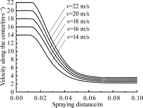
Fig.3 Spray distance and velocity curves for various initial velocity
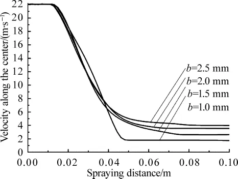
Fig.4 Spray distance and velocity curves for various nozzle gap w idth
It can be seen from Fig.4 that length of the potential core zone keeps nearly the same when the gap w idth raises from 1.0 to 2.5 mm,the outlet velocity is 22 m/s,and the length is 17 mm.The velocity will be improved when it enters into the developed zone with improvement of gap w idth.
Water will be diffused after it was sprayed out from the nozzle and velocity will be changed along the spraying direction during spraying process.Water volume fraction with various outlet velocity and gap w idth can be obtained when water enters into the developed zone according to the calculated data.Figure 5 is the water volume fraction in the cross section when the outlet velocity is 14-22 m/s and the gap w idth is 2.0 mm.Figure 6 is the water volume fraction when the outlet velocity is 22 m/s and the gap w idth is 1.0-2.5mm.Figure 7 is the water volume fraction distribution after water is sprayed 1 s from the nozzle.
It can be seen from Fig.5 that water volume fraction with different outlet velocity is nearly the samewhen thew idth is less than 3.0 mm and thewater volumewith lower outlet velocity is greater than the higher oneswhen thewidth is3.0-7.0mm.So the water can be defused quickly with higher velocity and the higher velocity is not good for decreasing spray diffusivity.The difference of water volume fraction with different velocity is not obvious and so the velocity cannot produce obvious effecton the water volume fraction in the developed zone.

Fig.5 Water volume fraction distribution along the w idth for different initial spray velocity
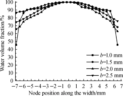
Fig.6 Water volume fraction distribution along the w idth for different nozzle gap width
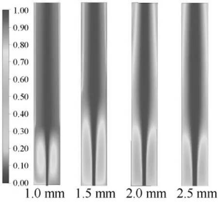
Fig.7 Water volume fraction distribution of the slot nozzle
It can be seen from Figs.6 and 7 that the gap w idth can affectwater distribution in the developed zone when the outlet velocity is a constant.Water volume fraction ismore than 80% when the w idth is less than 5.0 mm,and 80%water is within the 10 mm w idth range.So the gap w idth cannot affect spray diffusivity obviously within the range.But the gap w idth can affect spray diffusivity obviously in other w idth ranges,and the water can be diffused easily for smaller gap w idth.So the velocity along the center can be decreased quickly with increase of spraying distance,and the lower velocity was not good for water penetrating the residual layer on top of the strip.So the large w idth is suitable for decreasing spray diffusivity and improving cooling capacity.
3.2 Results and discussion for intensive nozzle
Water spraying processes were simulated according to the setting boundary conditions and the initial conditions when the outlet velocity of the intensive nozzle was 22 m/s and the diameter was 2.5-4.5 mm.The spraying processes were also simulated when the outlet velocity was 14-22 m/s and the diameter was 4.5 mm.The axial velocity was obtained when the outlet velocity and the diameter were different.Figure 8 is the axial velocity when the outlet velocity is14-22 m/s and the nozzle diameter is 4.5 mm.Figure 9 is the axial velocity when the outlet velocity was 22 m/s and the nozzle diameter is 2.5-4.5 mm.

Fig.8 Curves of spray distance and axial velocity with different initial spray velocity
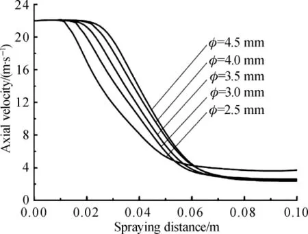
Fig.9 Curves of spray distance and axial velocity with different nozzle diameter
It can be seen from Fig.8 that the length of three regions remains unchanged when the outlet velocity raises from 14 to 22 m/s and the nozzle diameter is 4.5 mm.Lengths of the potential core zone and the developing zone are 26 and 54 mm respectively.Outlet velocity can affect water velocity in the developed zone,and water velocity in developed zone is greater with higher outlet velocity,and the axial velocity will keep constant after water enters into the developed zone.
It can be seen from Fig.9 that the length of the potential core zonewillbe increased when the nozzle diameter raises from 2.5 to 4.5 mm and the outlet velocity is 22.0 m/s.Axial velocity in the developing zone can also be improved with increase of nozzle diameter,but the axial velocity in the developed zone presents the opposite law.So water distribution along the spraying direction can be affected by nozzle diameter. Curve of nozzle diameter and length of the potential core zone is obtained according to the calculated data when the outlet velocity is 22.0 m/s and the nozzle diameter is 2.5-4.5 mm,and it can be seen in Fig.10.
It can be seen from Fig.10 that length of the potential core zone can be increased with improvement of nozzle diameter,and they present linear relationship.The scale factor is obtained by the least squaremethod and the value is 6.0.So the length of the potential core zone is about6.0 times the diameter of the round nozzle.
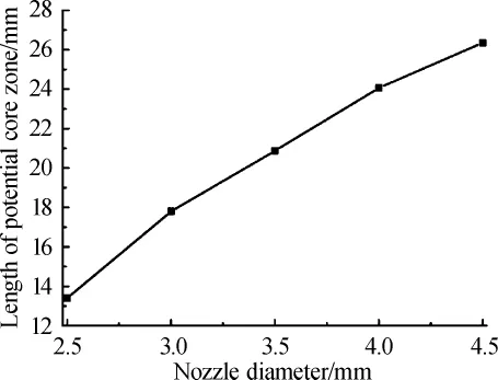
Fig.10 Relationship of nozzle diameter and length of the potential core zone
Water will be diffused after it was sprayed out from the nozzle and velocity will be changed along the spraying direction during spraying process.Water volume fraction with various outlet velocity and nozzle diameter can be obtained when water enters into the developed zone according to the calculated data. Figure 11 is the water volume fraction in the cross section when the outlet velocity is 14-22 m/s and the nozzle diameter is 2.0 mm.Figure 12 is water volume fraction when the outlet velocity is 22 m/s and the nozzle diameter is 2.5-4.5 mm. Figure 13 is the water volume fraction distribution after water is sprayed 1 s from the nozzle.
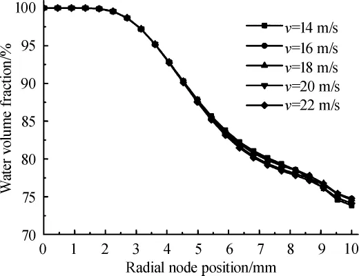
Fig.11 Radial water volume fraction distribution for different initial velocities
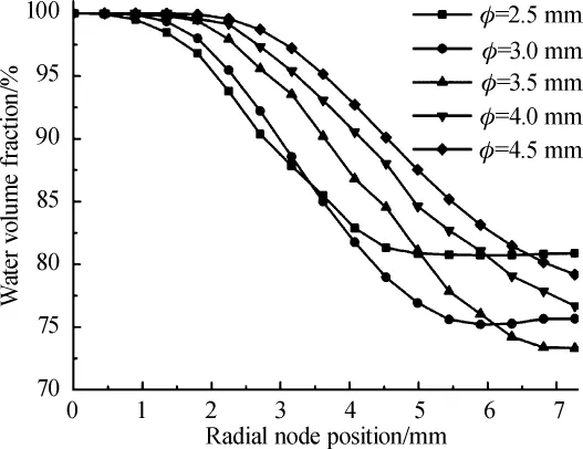
Fig.12 Radial water volume fraction distribution for different nozzle diameters
It can be seen from Fig.11 that the outlet velocity cannot affectwater volume fraction within diameter of 6.0 mm when the nozzle diameter is a constant.Water volume fraction can be affected by the outlet velocity in other ranges and water volume fraction is greater with higher outlet velocity.Butwater volume fraction has little difference with various outlet velocities.
It can be seen from Figs.12 and 13 that water volume fraction in the cross section can be affected by nozzle diameter,
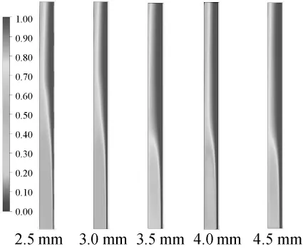
Fig.13 Water volume fraction distribution of the intensive nozzle
and itwill be decreased with increase of the distance from axis. Water volume fraction can be decreased greatly with smaller nozzle diameter.So the large diameter is suitable for decreasing spray diffusivity and improving of cooling capacity.
4 Practical Applications
Based on the superiority of ultra fast cooling in hot strip mill in development of low-cost and high property steel material,the cooling system in run-out table of 2 160mm HSM in Qian'an Iron and Steel had been modified.The best gap w idth(nozzle diameter)can be obtained according to the spray diffusivity changing law,required cooling rate and pump characteristic,and the two nozzles were designed.Figure 14 shows the nozzlemodel and its spraying status.
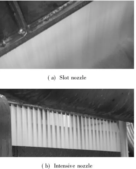
Fig.14 Spraying status for the two nozzle
The nozzle outlet velocity cannot be measured easily,but the water flux can be measured easily.The nozzle outlet velocity can be obtained from water flux according to flow conservation.The axial velocity and velocity along the center cannot bemeasured easily,but the width and diameter of water can be measured after it is sprayed out from the nozzle.The reliability of simulated data calculated by Fluent can be verified according to the w idth and diameter of water.
The diameter and w idth of water can be obtained from the calculated data at a constant spraying distance and the approximate value can also bemeasured when the water volume fraction is 90%.Tables 1 and 2 are the calculated and the measured data for slot nozzle and intensive nozzle respectively.

Table 1 Calculatedandmeasureddataforslotnozzle
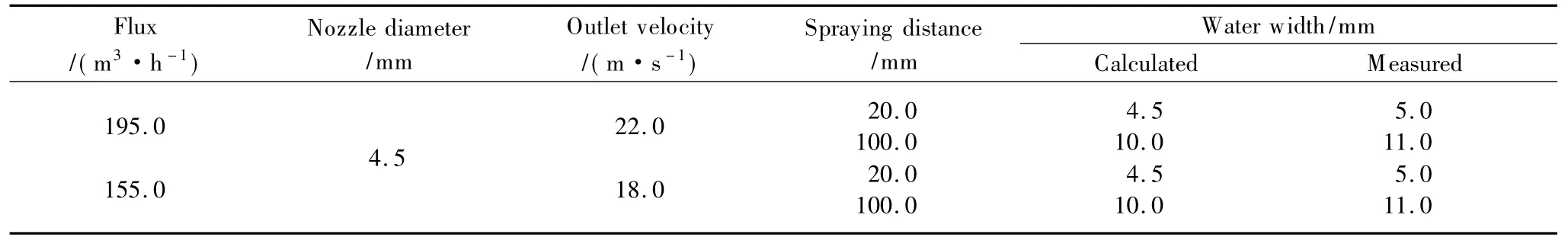
Table 2 Calculatedandmeasureddataforintensivenozzle
It can be seen from Tables 1 and 2 that the measured data are greater than the calculated data,but the deviation is not very great and the calculated data are acceptable. The machining quality of nozzle cannot be as good as the calculated model used in simulation,and the deviation can be smaller with higher machining quality.
It can be known from Fig. 14 that the water spraydiffusivity was of the two nozzles is not obvious and strength of the impinging jet flow is great. Strip cooling rate is improved greatly after the spraying cooling method is taken. Table 3 is the cooling rate for different steel grade.
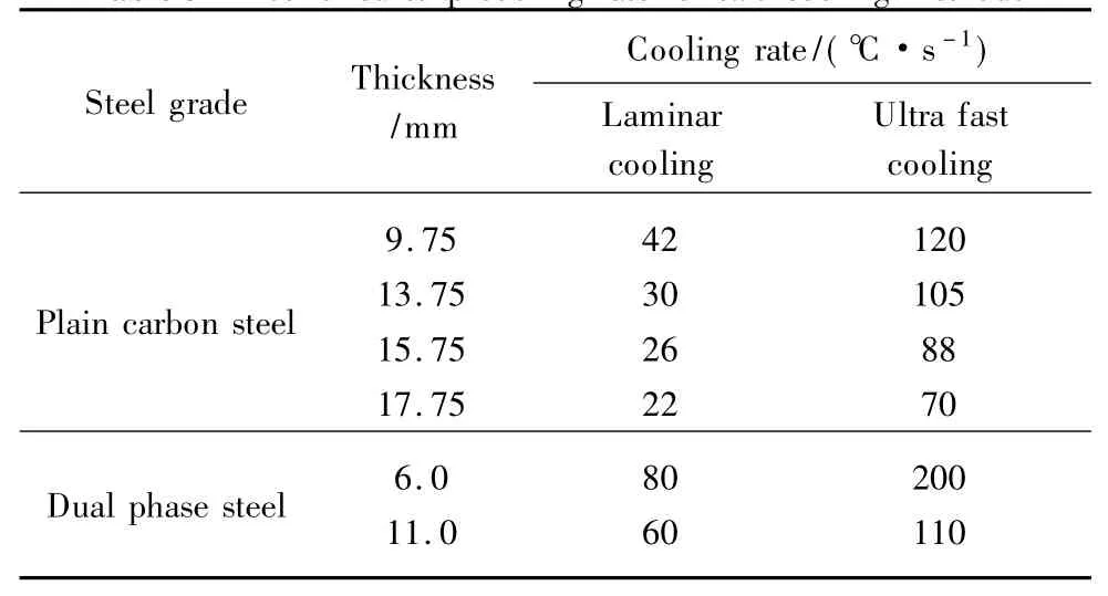
Table 3 Hotrolledstripcoolingratefortwocoolingmethods
It can be seen from Table 3 that the cooling rate isimproved greatly after the spraying cooling method with higherpressure is taken and it can provide useful references forestablishment of ultra fast cooling process. Slot nozzle gapwidth and intensive nozzle diameter are confirmed according tothe spray diffusivity changing law and range of required coolingrate.
5 Conclusions
( 1) Length of the potential core zone and the developingzone cannot be affected by the slot nozzle width and the outletvelocity when gap width of the slot nozzle was 1. 0-2. 5 mm andoutlet velocity was 14-22 m /s,and lengths of the potential corezone and the developing zone were 17 and 43 mm respectively.Water volume fraction in the developed zone could not beaffected by gap width and outlet velocity obviously,and 80%water was within the 10 mm width range.
( 2) Outlet velocity of the intensive nozzle could not affectwater volume fraction in the developed zone obviously.Intensive nozzle diameter could affect water volume fraction inthe developed zone within the setting range. Water volumefraction would be decreased with increase of distance from axisand it would be decreased greatly with smaller nozzle diameter.And large diameter was suitable for decreasing spray diffusivityand improving of cooling capacity.
( 3) Length of the potential core zone for intensive nozzlecould be increased with improvement of nozzle diameter andthey presented linear relationship when nozzle diameter was2. 5-4. 5 mm and outlet velocity was 14-22 m /s. Length of thepotential core zone was 6. 0 times the nozzle diameter. But theoutlet velocity could not affect length of the potential core zone.
[1] Li Z L,Jiang L Y,Yuan G,et al. Water Pressure ControlTechnology and Application on Hot Strip Rolling Water SupplySystem[J]. Journal of Northeastern University: Natural Science,2013,34( 9) : 1252-1256. ( in Chinese)
[2] Wang G D. New Generation TMCP and Innovative Hot RollingProcess [J]. Journal of Northeastern University: NaturalScience,2009,30( 7) : 913-922. ( in Chinese)
[3] Jiang L Y,Li Z L,Yuan G,et al. Research on Water Pressureand Nozzle Flux Control Method in Ultra-Fast Cooling System ofHSM[C]. The 9th China Steel Conference,Beijing,2013: 1-6.( in Chinese)
[4] Attalla M,Salem M. Effect of Nozzle Geometry on Heat TransferCharacteristics from a Single Circular Air Jet [J]. AppliedThermal Sciences,2013,51( 1) : 723-733.
[5] Gulati P,Katti V,Prabhu S V. Influence of the Shape of theNozzle on Local Heat Transfer Distribution between Smooth FlatSurface and Impinging Air Jet [J]. International Journal ofThermal Science,2009,48( 3) : 602-617.
[6] Sharif M A R. Heat Transfer from an Isothermally Heated FlatSurface due to Twin Oblique Slot-Jet Impingement[J]. ProcediaEngineering,2013,56( 3) : 544-550.
[7] Jeng T M,Tzeng S C,Xu R. Heat Transfer Characteristics of aRotating Cylinder with a Lateral Air Impinging Jet [J].International Journal of Heat and Mass Transfer,2014,70( 11) :235-249.
[8] Rusch D,Moser L,Roesgen T. Turbulence Model Validation forthe Fire Simulation by CFD and Experimental Investigation of aHot Jet in Cross Flow [J]. Fire Safety Journal,2008,43( 6) :429-411.Koseoglu M F,Baskaya S. The Effect of Flow Field andTurbulence on Heat Transfer Characteristics of Confined Circularand Elliptic Impinging Jets [J]. International Journal of Heatand Mass Transfer,2008,47( 10) : 1332-1346.
[9] Eren H,Celik N. Cooling of a Flat Plate by an ObliquelyImpinging Slot Jet [J]. International Communications in Heatand Mass Transfer,2006,33( 3) : 372-380.
[10]Akansu Y E,Sarioglu M,Kuvvet K,et al. Flow Field and HeatTransfer Characteristics in an Oblique Slot Jet Impinging on a FlatPlate[J]. International Communications in Heat and Transfer,2008,35( 7) : 873-880.
[11] Du C,Xu M Y,Mi J C. Effect of Exit Reynolds Number on aTurbulent Round Jet [J]. Act Physica Sinica,2010,59 ( 9 ) :6331-6338. ( in Chinese)
[12] Rusch D,Moser L,Roesgen T. Turbulence Model Validation forthe Fire Simulation by CFD and Experimental Investigation of aHot Jet in Cross Flow [J]. Fire Safety Journal,2008,43( 6) :429-411.
[13] Abdel-Fattah A. Numerical and Experimental Study of TurbulentImpinging Twin-Jet Flow [J]. Experimental Thermal and FluidScience,2007,31( 8) : 1061-1072.
[14] Chen Q G,Xu Z,Zhang Y J. Advances in Numerical Studies ofTurbulent Impinging Jet Flow and Heat Transfer[J]. Advancesin Mechanics,2002,32( 1) : 92-105. ( in Chinese)
TG335.55
A
1672-5220(2015)04-0583-05
date:2014-04-21
s:State“1025”Science and Technology Support Projects,China(No.2012BAF04B01)
*Correspondence should be addressed to JIANG Lian-yun,E-mail:neu2015@163.com
猜你喜欢
东方少年(2022年25期)2022-10-18
安徽农业科学(2022年9期)2022-05-17
无人机(2021年1期)2021-04-05
金色年华(2017年10期)2017-06-21
中国篆刻·书画教育(2017年5期)2017-06-08
学习月刊(2015年1期)2015-07-11
爆笑show(2014年1期)2014-06-23
故事会(2009年23期)2009-07-15
 Journal of Donghua University(English Edition)2015年4期
- Journal of Donghua University(English Edition)的其它文章
- Numerical Reality Method of the M icroburst Model
- Corporate Governance,Government Regulation and Bank Stability
- Cracking Patterns of Shear Walls in Reinforced Concrete Structure due to Strong Earthquake Based on Mohr-Coulomb Criterion
- Cooperative Compressive Spectrum Sensing in Cognitive Underwater Acoustic Communication Networks
- Numerical Simulation of Gas-Solid Two-Phase Flow in Reverse Blow ing Pickup Mouth
- Fuzzy Model Free Adaptive Control for Rotor Blade Full-Scale Static Testing