
Pouring characteristics analysis on the concrete pump truck boom based on rigid-flexible coupling method
2015-10-29 07:15JuanHUANGJiangyongWANGTiezhongXIAO
机床与液压 2015年4期
Juan HUANG, Jiang-yong WANG, Tie-zhong XIAO
(1Department of Mechatronics Engineering, Sichuan Engineering Technical College, Deyang 618000, China)(2Changzhi Qinghua Machinery Factory, Changzhi 046000, China)
Pouring characteristics analysis on the concrete pump truck boom based on rigid-flexible coupling method
Juan HUANG1*, Jiang-yong WANG2, Tie-zhong XIAO1
(1DepartmentofMechatronicsEngineering,SichuanEngineeringTechnicalCollege,Deyang618000,China)(2ChangzhiQinghuaMachineryFactory,Changzhi046000,China)
Concrete pump truck boom belongs to large flexible manipulator, and it always works in adverse environment. Due to the influence of exciting force and concrete load, pump truck boom produces vibration, which affects the casting quality and boom strength. Aiming at the fixed-point pouring working condition, the forces on the boom were calculated. The concrete pump truck boom’s rigid-flexible coupling model was established based on ANSYS and ADAMS software, and both of the high pressure and low pressure working condition were simulated, and its strength was calculated, which showed that the boom could meet the design requirements. The simulation results show that this method is suitable for the simulation of large flexible mechanical boom, and it could provide theoretical guidance for such structure’s design and checking.
Pump truck boom, Rigid-flexible coupling, Strength, Vibration
1 Introduction
Concrete pump is a special vehicle because pumping mechanism and boom systems are integration mounted on the vehicle chassis. During pouring operations, pump could transmit the power provided by chassis engine to the pump through the transfer case, thereby drive concrete pumping mechanism and boom system. Pump working environment was bad and boom was shaking incessantly in pouring process due to cyclical shocks of pump and boom flexible effects, which will not only affect the casting quality, but also lead to fatigue failure.
Rigid-flexible coupling model for the concrete pump truck boom was established based on ANSYS and ADAMS software in this paper. Its most dangerous working conditions, namely the level of working conditions were analyzed. Based on the results, the boom strength was checked, which had some reference value for truck boom design and checking.
2 Build virtual prototype model
ADAMS, as a large-scale dynamics analysis software, the main analysis target was rigid body and could ignore the impact of its flexible effects caused by the movement [1]. ANSYS as finite element analysis software could analyze the object stress, strain and natural frequency and other characteristics. But for the assemblies and a large range of motion object, its analysis capabilities was weak [2-3]. Through bidirectional interface between these two software, movement analysis and strength checking could be carried on for large flexible parts.
In ANSYS through modal analysis for parts, modal neutral file (ie.mnf file) of flexible body could be generated. Import this file into ADAMS, flexible body model will be generated, thus the deformation produced by dynamics simulation process in flexible body and influence on the hinge of force generated by the deformation could be analyzed. Then in system dynamics computing, deformation influence of flexible body and coupling between flexible body and rigid body could be considered, which will improve the reliability of the simulation results, so the simulation results will be more close to the real situation [4-6].
Conversely, after the completion of the system analysis in ADAMS, flexible or rigid body forces information could be exported, and load files (ie .lod file) could be generated. The file was read into ANSYS software, then parts load spectrum information could be produced in the specified time period or the specified time, the boundary conditions of parts was formed, and then we could carry out static analysis, transient response and fatigue life prediction and research. This boundary condition was based on the dynamics accurate simulation results, which eliminates the need for complex manual calculations, could greatly improve the efficiency and accuracy [7]. Co-simulation flow chart between ANSYS and ADAMS was shown in Fig.1.
Fig.1 Co-simulation between ADAMS and ANSYS
3 Establish rigid - flexible coupling mo-del
Concrete pump truck boom was longer and larger ranges of motion, then the flexibility effects were obvious as compared to other parts. In this paper, flexible body models of only four sections boom were established; turntable, hydraulic cylinders, connecting rods and other parts were regarded as rigid body. 3D model of pump truck boom was established in three-dimensional software named Solidworks, as shown in Fig.2. Firstly, the multi-body model of boom system was established in ADAMS, set the unit to MKS (length, mass, force, time, degree deg), the acceleration of gravity was 9.8. Boom material was a certain type of imported steel, the density was 7850, Young’s modulus was 2.1E11, Poisson’s ratio was 0.3. After defining the materials, mass and inertia of each component was determined automatically. Meshing on the boom in ANSYS, boom modal neutral file (.MNF) was generated. By Rigid to flex module in ADAMS, four boom modal neutral files generated in ANSYS separately introduced into ADAMS, then the multi-body model corresponding parts were replaced. And ensure that the centroid of two parts could coincide, Re-add the constraint, rigid - flexible coupling model of boom system was generated.
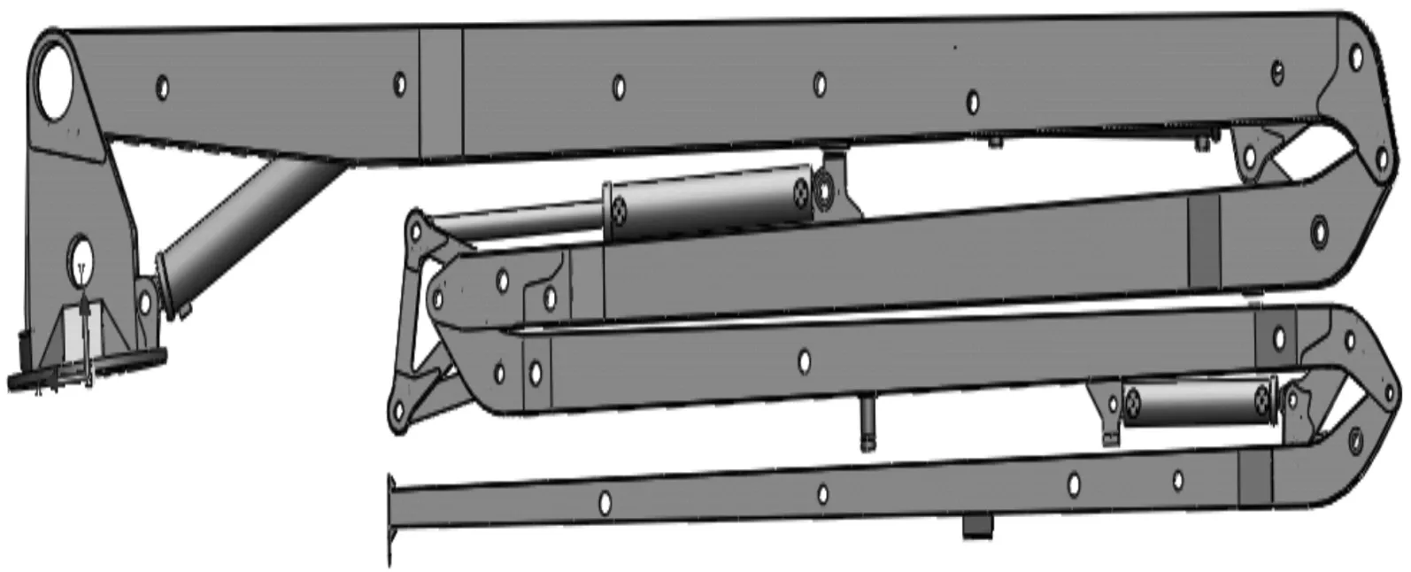
Fig.2 The boom assembly
4 Analysis of the boom vibration characteristics
4.1Excitingcalculation
When concrete pump was working, concrete pumps worked alternately and concrete was pumped to the specified pouring location through the delivery tube. Periodic exciting force was produced by this alternative working of pump, leading to the boom vibration. The exciting force at the turntable and the pump truck boom force generated by extremity hose when concrete flowing were considered in this paper.
1) Turntable exciting force computing
When the displacement of concrete was 110 m3/h, the amplitude of the pump turntable is about to 0.004 4 m [8]. The displacement was 130 in pump low pressure working condition and the displacement was 76 in pump high pressure working condition. Based on proportional relationship, the corresponding amplitude of the turntable at the two conditions could be calculated as 0.005 2 m and 0.003 04 m, respectively.
According to the pump parameters, during low pressure working condition, theoretical pumping frequency of pump was 25 times per minute, so the excitation function of turntable displacement is as follows:
(1)
During high pressure working condition, theoretical pumping frequency of pump was 15 times per minute, so the excitation function of turntable displacement is as follows:
(2)
2) Extremity concentrated load calculation
The maximum flow rate of concrete in delivery pipe was calculated as follows:
(3)
Where,Qwas the representatives of theoretical flow;rwas the representatives of delivery tube radius, according to the pump parameters,rwas taken to 0.062 5 mm.
When concrete flowing in the extremity hose, which was considered the free fall, the exit velocity of concrete could be determined as follows:
(4)
Where,gwas acceleration of gravity;Lwas the length of extremity hose, according to the pump parameters ,Lwas taken to 3 m.
The average flow velocity of concrete in hose was
(5)
The extremity hose frictional force generated by concrete was
F=2πrL(K1+K2Vm)×2
(6)
Where,K1was sticking coefficient,K2was speed coefficient, their units were Pa and Pa/(m·s-1), respectively, concrete slumpSwas taken to 16 mm, according to the empirical formula, they could be calculated as follows:
K1=(3.1-0.1S)×102=150Pa
(7)
(8)
Use the formula from Eqs.(3) to (8), the pump parameters were obtained at low pressure flow and high pressure flow pump, as shown in Table 1.
4.2 Simulation
In ADAMS, the turntable and the earth were set moving deputy, adding slip deputy driving, excitation function as shown in formula (1) and (2). Applying a concentrated force in the extremity boom, the force was shown in Table 1. Simulation time was 20 s, step length was 0.1. Vibration displacement of extremity point was measured at low pressure working condition, as shown in Fig.3. At low pressure working condition, when the initial work, the maximum amplitude of extremity boom was reached up to 1.84 m, due to the damping effect, boom amplitude was decreased and eventually it was around 0.92 m.
Table 1 The velocity of concrete and the terminal friction force
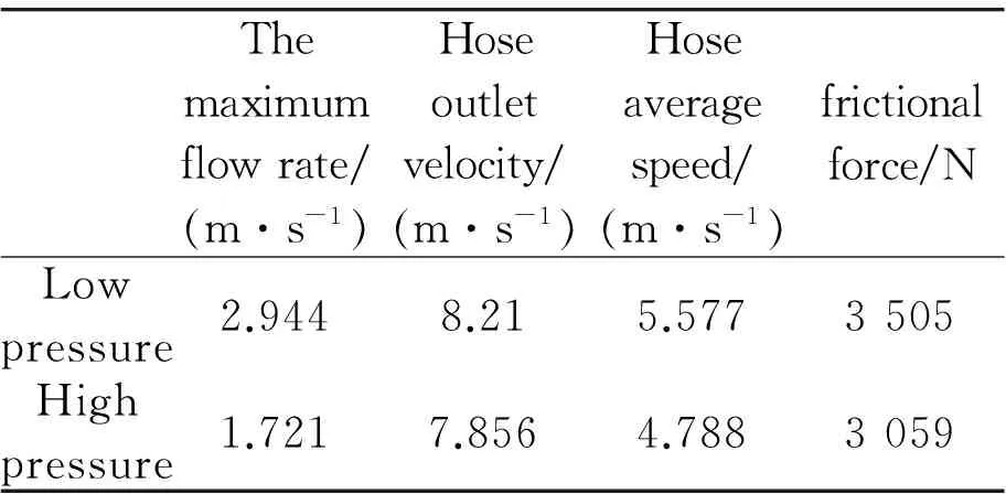
Themaximumflowrate/(m·s-1)Hoseoutletvelocity/(m·s-1)Hoseaveragespeed/(m·s-1)frictionalforce/NLowpressure2.9448.215.5773505Highpressure1.7217.8564.7883059
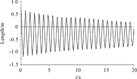
Fig.3 The displacement of end point
The acceleration of end point was measured at low pressure working condition, as shown in Fig.4. If the acceleration Fourier transform was conduct, the results were shown in Fig.5. It could be seen that boom first order frequency was around 1.25 Hz, second-order natural frequency was about 2.46 Hz, three natural frequencies was approximately 3.71 Hz, much greater than the pumping frequency of pump, so the designed pump could meet the requirements.
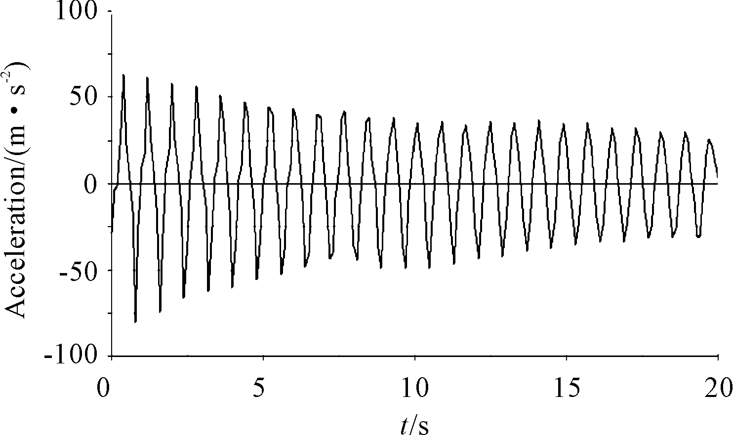
Fig.4 The acceleration of end point
Similarly, conduct the simulation at high pressure working condition, the maximum amplitude of pump in the initial stage was 1.69 m, and the final amplitude was about 0.9 m. So pump vibration was greater than that at low pressure working condition.
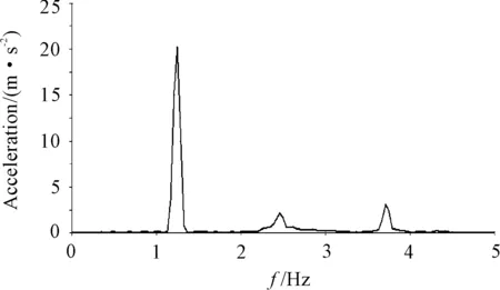
Fig.5 The Fourier transform of acceleration
5 Boom strength analyses
According to the analysis above, we can see that compared to the boom luffing movement and rotary motion, the vibration of the boom when pouring had a greater impact on its strength, and the strength of the boom when pouring was checked. The simulation parameters were set as indicated above, the force was measured at each joint, as shown in Fig.6(a) and Fig.6(b).
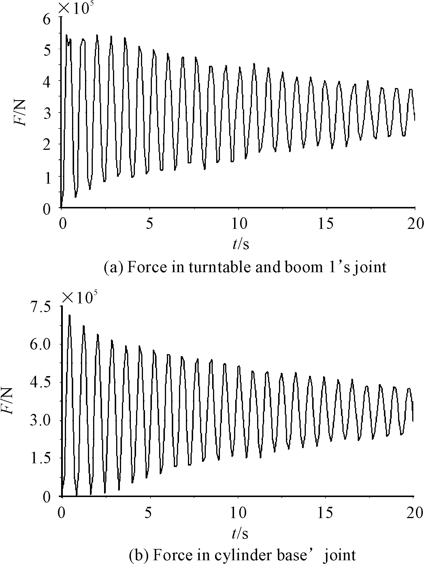
Fig.6 Force
Analysis of force curves at each joint, compared to the rigid model, flexible boom force of all the joints showed considerable volatilities, and boom fatigue damage was caused in the actual work. At the beginning of pouring, force at each boom joint was the maximum and fluctuate, then force become gradually stabilized over time. From this figure, it can be seen that the joints force when time was 0.4 s reached the maximum, at this time the deformation of the boom was maximum.
Based on the above analyses, select File-Export in ADAMS, then select the first boom, loads each external point of the boom on 0.4 s were outputted, generate finite element load files [9]. Run ANSYS and open a finite element model of the first boom. Add displacement constraints at the hinge point, import load files and carry out static analysis. The stress situations throughout boom were shown as Fig.7.
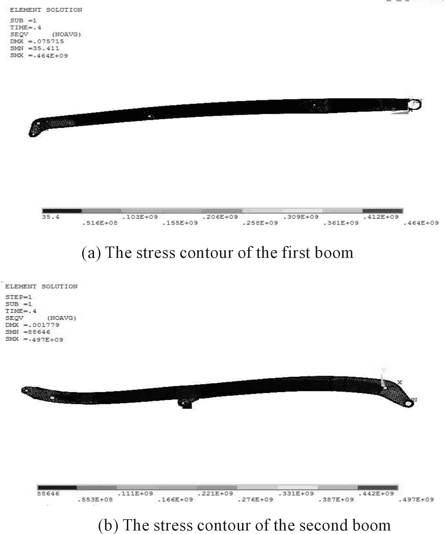
Fig.7 The stress contour of the boom
From Fig. 7, the maximum stress of the first boom was 464 MPa, the maximum stress of the second boom was 497 MPa, which could meet the strength design requirements. Since there was no consideration reinforcement ring influence, the forces at hinge and cylinder base were large. If reinforcement ring was increased, the force at the boom hinge would be appropriately reduced, and boom could safely run.
6 Conclusions
Based on ANSYS and ADAMS simulation platform, boom as a flexible body, a rigid-flexible coupling model of concrete pump truck boom was established. Turntable exciting force and extremity concentrated load at level working conditions were calculated, and the boom dynamics simulation was carried out. Based on the above simulation results, the boom displacement fluctuation characteristics were analyzed. And boom strength was checked. It has been confirmed that the boom flexible effect will not only affect the boom movements, but also affect the stress and strain of boom. Therefore, this paper could provide the study basis for the simulation of flexible manipulators.
Acknowledgement
This paper is supported by Chongqing Municipal Education Commission of Science and Technology research project (No.KJ130806)
[1]YUAN S Q, XU Q Y, ZHANG G L. Experiments on active vibration control of a flexible four bar linkage mechanism [J].ASME Journal of Vibration and Acoustics, 2002, 122(1): 82-85.
[2]Li Zhibo,Yu Hongyun. Pro/E, ADAMS and ANSYS combined application of virtual design [J]. Mechanical Engineering and Automation,2008,2: 48-53.
[3]Chen D, Wang G, Xie X F. Research on Dynamic Characteristics of Boom System Vibration of Concrete Pump Truck[J]. Machine Design and Research, 2011, 27(4): 92-95.
[4]Pu Minghui, Wu Jiang. Study on cane flexible body modeling based on ADAMS [J]. Journal of System Simulation,2009,21(7):1930-1932.
[5]Hao Jungang. Interface between CAE and CAD three-dimensional software [J].AECC topics symposium proceedings,2007: 84-86 .
[6]Zhao LiJuan, Ma Yongzhi. Study on rigid - flexible Coupling System Modeling and Key Technologies [J]. Computer Engineering and Applications,2010, 46(2):243-248.
[7]Andreas H, Martin A, Ondrej V. Modal multifield approach for an extended flexible body description in multibody dynamics [J]. Multibody System Dynamics (S1384-5640), 2005, 13(3): 299-322.
[8]Tian Runli,Lv Pengming,Jia Jianfeng. Study on concrete Pump Truck system transient dynamic response [J]. Construction machinery,2010(3): 85-91.
[9]Taddei F, Martelli S. Finite element modeling of Researching Hip prosthesis: Estimation of Accuracy through Experimental Validation [J]. Biomech. Eng.2010, 132, 11.
10.3969/j.issn.1001-3881.2015.24.020 Document code: A
TU646
基于刚柔耦合的混凝土泵车臂架浇筑特性分析
黄娟1*,王江勇2,肖铁忠1
1.四川工程职业技术学院 机电工程系,四川 德阳618000;2.长治清华机械厂,山西 长治046000
混凝土泵车臂架属于大型柔性机械臂。由于受到激振力和混凝土载荷的影响,泵车臂架在工作中产生振动,影响浇筑质量和臂架强度。针对泵车水平定点浇筑的工况,计算了泵车臂架所受载荷,基于ANSYS和ADAMS软件建立了混凝土泵车臂架的刚柔耦合模型,对臂架水平状态下高压和低压工况进行了仿真,并计算了臂架强度,验证了该臂架满足设计要求。仿真结果表明: 该方法适用于大型柔性机械臂的仿真,可以为该类结构的设计与校核提供理论指导。
泵车臂架;刚柔耦合;强度;振动
9 February 2015; revised 15 April 2015;
Juan HUANG, Master.
E-mail: daisyjenny@163.com
accepted 13 June 2015
Hydromechatronics Engineering
http://jdy.qks.cqut.edu.cn
E-mail: jdygcyw@126.com
猜你喜欢
湖南水利水电(2021年6期)2022-01-18
科学与财富(2021年35期)2021-05-10
中国工程机械学报(2019年6期)2019-12-31
进出口经理人(2016年15期)2017-05-10
制造业自动化(2017年2期)2017-03-20
专用汽车(2016年7期)2016-11-23
大连理工大学学报(2016年5期)2016-10-12
长江大学学报(自科版)(2016年29期)2016-03-25
机电信息(2015年3期)2015-02-27
机电产品开发与创新(2014年2期)2014-01-28
- 机床与液压的其它文章
- The design of control system applied in artificial grass tufting machine adopting servomotors
- Research on active suspension control strategy based on fuzzy PID control
- Automobile magnetorheological damper multi-objective optimization analysis
- Co-simulation and consumption analysis of wheel loader on negative loading condition
- Influence of the underlap in the poppet valve on its performance
- Comprehensive reliability evaluation of foreign high-end gantry machining Center