
Hydrodynamic modelling of flow impact on structures under extreme flow conditions*
2016-10-14 12:23QiuhuaLIANGKaicuiCHEN陈恺翠JingmingHOUYanXIONG熊焱GangWANG王岗JuanQIANG羌娟
水动力学研究与进展 B辑 2016年2期
Qiuhua LIANG,Kai-cui CHEN (陈恺翠),Jingming HOU,Yan XIONG (熊焱),Gang WANG (王岗),Juan QIANG (羌娟)
1.Key Laboratory of Coastal Disaster and Protection,Ministry of Education,Hohai University,Nanjing 210098,China
2.School of Civil Engineering and Geosciences,Newcastle University,Newcastle upon Tyne,England,UK,E-mail:Qiuhua.Liang@ncl.ac.uk
Hydrodynamic modelling of flow impact on structures under extreme flow conditions*
Qiuhua LIANG1,2,Kai-cui CHEN (陈恺翠)1,Jingming HOU2,Yan XIONG (熊焱)1,Gang WANG (王岗)1,Juan QIANG (羌娟)1
1.Key Laboratory of Coastal Disaster and Protection,Ministry of Education,Hohai University,Nanjing 210098,China
2.School of Civil Engineering and Geosciences,Newcastle University,Newcastle upon Tyne,England,UK,E-mail:Qiuhua.Liang@ncl.ac.uk
Apart from the direct threat to human lives,the flood waves as a result of the rapid catchment response to intense rainfall,breaches of flood defences,tsunamis or storm surges may induce huge impact forces on structures,causing structural damage or even failures.Most existing design codes do not properly account for these impact forces due to the limited understanding of the underlying physical processes and the lack of reliable empirical formulae or numerical approaches to quantifying them.This paper presents laboratory experiments to better understand the interaction between the extreme flow hydrodynamics and the hydraulic structures and uses the measured data to validate a numerical model.The model solves the two-dimensional shallow water equations using a finite volume Godunov-type scheme for the reliable simulation of complex flow hydrodynamics.New model components are developed for estimating the hydrostatic and hydrodynamic pressure to quantify the flow impact on structures.The model is applied to reproduce two selected experiment tests with different settings and satisfactory numerical results are obtained,which confirms its predictive capability.The model will therefore provide a potential tool for wider and more flexible field-scale applications.
wave-structure interaction,extreme flow conditions,flood hazards,shallow flow model,laboratory experiments
Introduction
The flood events as a result of the rapid catchment response to intense rainfall,failure of flood protection measures,tsunamis or storm surges are usually highly transient in nature and have the features of extreme flow conditions.Apart from their direct threat to human lives,the resulting rapidly varying flood waves may also create tremendous impact forces on structures,causing structural damage or even failures.For instance,the 2011 east Japan tsunami killed more than 15 000 people and significantly damaged or destroyed numerous buildings,bridges and other infrastru-ctures,in a country which can be described as one of the most advanced economies and most earthquake-prepared nations.A large number of papers and reports were published to document the field surveys to show the significant structure damage caused by this and other tsunami events[1-3].In 2005,Hurricane Katrina together with subsequent floods caused a death toll of at least 1 833 people and the property damage of $1.08×10¹¹(USD in 2005).Then in 2012,Superstorm Sandy,the largest Atlantic hurricane on record,affected 24 states in the USA and several other countries,killed 286 people along its path and left over $6.8×10¹⁰(USD in 2013) in damage.In the UK,a flash flood following an intense rainfall event caused substantial damage to the historic Cornish town of Boscastle in 2004,with some 70 properties flooded,and over 100 cars,caravans,and several boats washed into the sea.There are numerous similar events worldwide that can be also listed here.Supported by a number of recent studies,it is generally recognized that meteorological and hydrological extremes,inclu-ding storms and different types of floods,will become more frequent and cause more significant economic losses throughout the 21st century[4].Therefore,it is necessary to review the current building practice and update our design and construction approaches in order to build more resilient communities under climate changes.
In urban areas,some researches were carried out for different types of loading induced on buildings due to floods[5].Kelman and Spence[5]gave a good overview of the various potential forces that arise during a flood event,and pointed out that the most important factors in the flood damage assessment are the lateral pressure imparted by the different height of water inside and outside of the building and the lateral pressure due to the water velocity.However,how to quantify these flood impacts remains to be explored and the current practical design still commonly relies on the use of empirical formulas to obtain rough and unverified estimations of these hydraulic loadings.
On coastal flooding,assessments were made for the modes of structural failure due to storm surges or tsunamis,e.g.,in New Orleans after Hurricane Katrina in 2005[6,7].However,as pointed out by Nistor et al.[3],most of the existing design codes do not properly take into account the impact forces under extreme hydraulic conditions caused by tsunamis and other analogous events.Similar to the urban applications,the existing empirical formulas for quantifying these forces for design are in a significant disagreement with observations.Therefore,there is an urgent need to fill the current knowledge gap.The new knowledge and tools are crucial for evaluating more reliably the possible structure damage caused under extreme flow conditions by tsunamis or other extreme disastrous events,which will in turn provide better guidelines and codes for city planning and structural design.
In the last two decades,numerous two-dimensional hydrodynamic modelling tools have been developed and widely applied to simulate different types of floods[8-11].Most of these applications focus on the flood extent and water depth,from which flood damage is estimated without considering the actual hydraulic impacts on structures.These models,particularly,the shock-capturing hydrodynamic flood models,can well predict the detailed velocity field and flow depth in a simulation,which may be extended to directly evaluate hydraulic loads on structures caused by different types of floods.Ghadimi and Reisinezhad[12]reported an attempt to assess the flood impact on cylindrical piers using a finite element shallow water model integrated with a formula derived from the Bernoulli principle for calculating pressure forces.
Based on the current research need,this paper presents laboratory experiments to better understand the interaction between the extreme flow hydrodynamics and structures,with experimental measurements to validate a two-dimensional depth-averaged shallow flow model.The model solves the two-dimensional shallow water equations and a finite volume Godunovtype scheme for automatic tracking of wet-dry fronts[13].A new component is developed to calculate hydrostatic and hydrodynamic pressures and the corresponding forces.The model can be used to evaluate the flood impacts for different types of floods,including those extreme events driven by tsunamis,storm surges and flash floods.The formulas for pressure calculation are different from those used by Ghadimi and Reisinezhad[12]and are validated by new experimental measurements.The model may provide a robust tool for more flexible field-scale applications.
1.Numerical model
1.1 Governing equations
The shallow water equations (SWEs) are used to describe a wide range of flow hydrodynamics with horizontal dimensions much larger than water depth,including the discontinuous dam-break waves.Therefore,the hyperbolic conservation laws of the SWEs are adopted in this paper in the mathematical model for quantifying the fluid-structure interaction under extreme flow conditions.In a matrix form,the governing equations may be written as
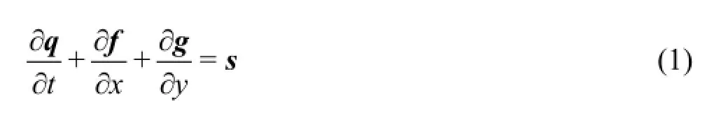
wheret,xandy ,respectively,represent the time and the two horizontal coordinates,q,f,gands are the vectors of the flow variables,x -and y-direction fluxes and the source terms,which,when neglecting the Coriolis effects and the surface stresses,can be expressed as follows:
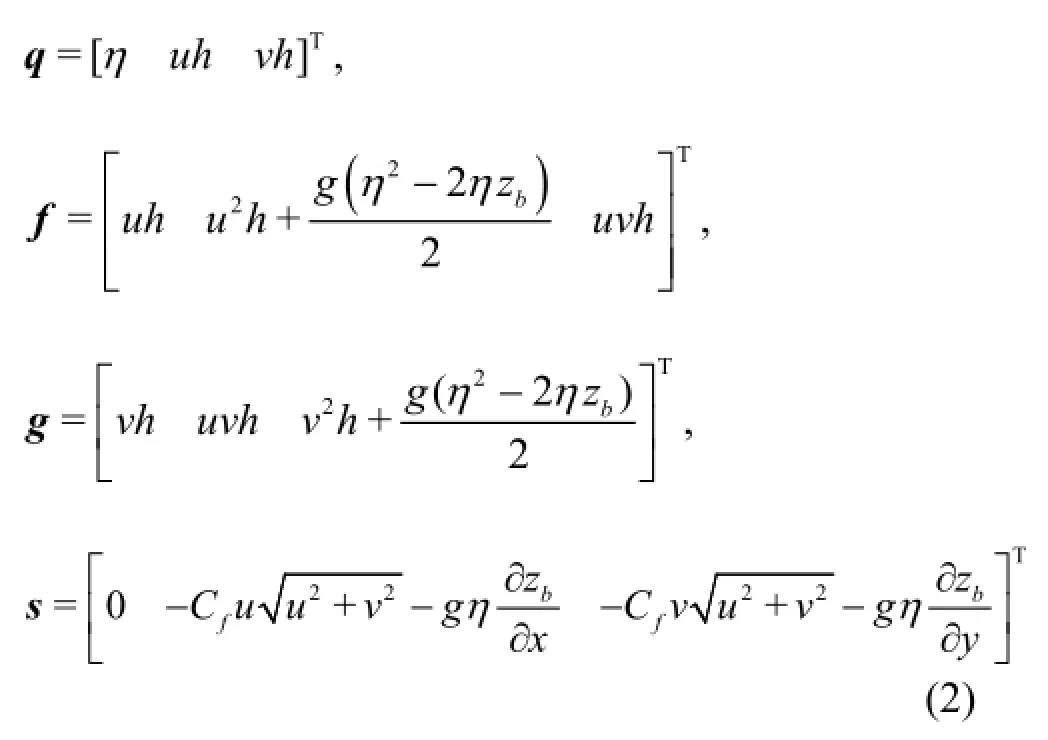
where η is the water level above the datum,uandv are the x -and y-direction depth-averaged velocity components,his the total water depth with zbbeing the bed elevation above the datum,g represents the acceleration of gravity,Cfis the bed roughness coefficient,-∂zb/∂xand -∂zb/∂yare the bed slopes in thex -and y-direction.These vector terms were derived in Liang and Borth wick[14]by adopting the water level,instead of water depth,as one of the flow variables,which automatically ensure the well-balanced solution[15]of the problem of a lake at rest.
1.2 Numerical method
The proposed numerical model is used in this paper to solve the above SWEs using a second-order finite volume Godunov-type scheme implemented with an HLLC approximate Riemann solver[16]for evaluating the interface fluxes.The second-order accuracy in both space and time is achieved by implementing the two-step MUSCL-Hancock method through a predictor step and a corrector step.The predictor step predicts intermediate values of the flow variables over a half time step ∆t/2using the following formula
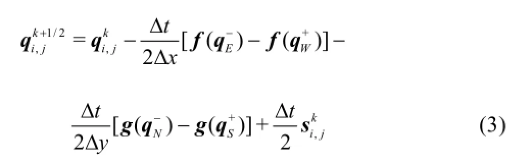
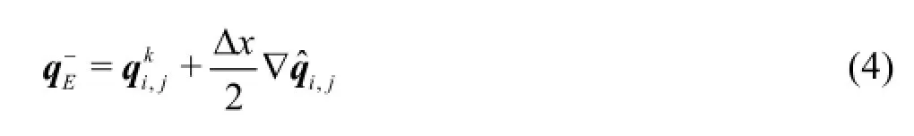
whereiandj are the cell indices,E,W,Nand Sdenote the “East”,“West”,“North” and “South”cell interfaces,krepresents the time level,and “-”and “+” indicate the left and right hand sides of an arbitrary cell interface,∆xand ∆yare the cell sizes in the two Cartesian directions.In order to evaluate the flux functionsthe face values of the flow variables must be firstly reconstructed at the mid-points of all four cell interfaces using the MUSCL linear reconstruction[17].Taking the eastern interface as an example,can be reconstructed by
The corrector step of the MUSCL-Hancock method updates the flow variables over a full time step using the following time-marching formula
where fE,fW,gNand gSare the four Godunovtype numerical fluxes obtained by solving the local Riemann problems defined respectively at each of the four interfaces of the cell under consideration,e.g.,
1.3 Pressure model
The interaction between the flood waves and structures during a tsunami,a storm surge or other extreme hydrodynamic events is physically very complex and may involve a number of different processes and forces,e.g.,hydrostatic and hydrodynamic forces,buoyancy,waterborne debris impacts,wave loadings,and effects of scour and erosion[19].This paper focuses on the dominating loadings caused by hydrostatic and hydrodynamic pressures,which will be calculated using the flow variables obtained through solving the SWEs.
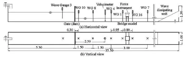
Fig.1 Vertical and horizontal views of the experimental flume and experimental setup (m)
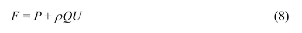
In open channel flows,any section of fluid is subject to a force with two components according the momentum principle,which may be classified as the hydrostatic pressure force and the hydrodynamic force.The hydrodynamic force is typically the momentum of the fluid at the section under consideration,i.e.,ρQU,whereρis the density of the water,Qis the total discharge through the cross-section andUis the average velocity.Denoting the pressure force asP ,the total force is therefore
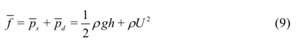
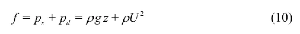
where psand pdare,respectively,the hydrostatic and hydrodynamic components of the point pressure,zis the depth from the water surface to the point of interest,since U is a constant in the vertical direction.In this paper,Eqs.(9) and (10) are implemented within the aforementioned finite volume shallow flow model to estimate different pressure components.
2.Laboratory experiments
In order to better understand the physics of extreme hydrodynamic flows impacting on structures and to obtain measured data for validating numerical models,laboratory experiments are designed and carried out in a 1 m wide flume at the hydraulic laboratory in Hohai University,China.The flume is 35.5 m long and a section of it is used in the current experimental tests,as shown in Fig.1.
In view of the fact that the overland flows caused by tsunamis or other severe coastal flood events typically move inland as a surge that is hydraulically similar to the rapidly propagating dam-break wave fronts.In case of flash flooding,the destructive “walls of water” moving from the upstream steep catchment to the downstream river channels and the floodplain are also similar to dam-break waves.Therefore,dambreak waves are created to represent the extreme flow conditions under consideration in the current experiments.Dam-break waves were also used by other researchers[3]to investigate the tsunami impacts.
The experimental layout is illustrated in Fig.1 with a gate installed in the channel to form an upstream reservoir.Two sidewalls of the channel are made of glasses supported and connected by steel brackets,while the bottom is made of cement and is painted to be a smooth surface.During the experiments,the gate will be lifted instantaneously to produce dam-break waves.Scaled-down bridges with single and double piers are used to represent the impacted hydraulic structures.The dimensions of the bridges are presented in Fig.2.Over 30 experiments are performed with different water depth upstream and downstream the dam,including the dry bed cases,to investigate the impact of dam-break waves of different magnitudes on the structures.Time histories of the water depth are recorded at seven calibrated wave gauges installed along the channel at locations as indicated in Fig.1.The sampling interval of wave gauges is 0.003 s.A high-resolution acoustic Doppler velocimeter (NortekVectrino II) is used to measure the water velocity.Six pressure sensors are fixed onto the bridge piers to measure the receiving impact and their locations are indicated in Fig.2.The acquisition frequency of the pressure sensors is 5 000 Hz.All experimental measurements are analysed for better understanding the complex interacting processes between the sharpfronted dam-break waves and the structures and are archived for the model validation as presented in the next section.
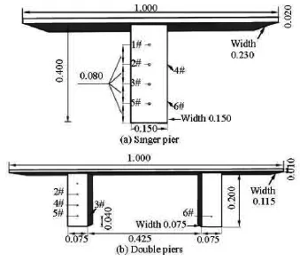
Fig.2 Bridge models and location of the pressure sensors (m)
3.Numerical results
In this section,the proposed finite volume Godunov-type shallow flow model is validated for predicting the fluid-structure interaction and quantifying the impacting pressure under the extreme flow conditions induced by dam breaks by applying it to reproduce the laboratory experiments as introduced in Section 2.Among the series of experiments being conducted,two are selected herein to validate the numerical model,respectively,for the bridge structures with a single pier or double piers.Open and closed boundary conditions are used during the numerical simulations and the detailed implementation can be found in Liang and Borthwick[14].The CFL number in the Courant-Friedrichs-Lewy (CFL) criterion is set to 0.5 to ensure numerical stability.g =9.81m/s2and ρ=1000 kg/m3.
3.1 Single-pier test
The 15 m × 1 m flume section is chosen to be the computational domain,including the reservoir upstream the dam and 9.5 m long downstream valley that covers the bridge structure and all of the measuring devices.The downstream boundary is 3.5 m away from the nearest wave gauge.During the simulation,a uniform grid of 1 500×100 cells is used for a 0.01 m spatial resolution in order to accurately represent the bridge structure and the locations of all measuring devices.The Manning coefficient is set to be 0.01 s/m1/3.Open boundary conditions are imposed at the downstream end of the computational domain and all other three domain edges are assumed to be closed.The simulation is run for 25 s,with the initial still water depth of 0.4 m and 0.198 m upstream and downstream the dam,respectively.
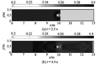
Fig.3 Single pier:Water-structure interaction at sampling output times
Figure 3 presents the simulation results in terms of plan-view water surface plots at two different output times.After the dam/gate opens at t=0s,a sharp-fronted shock wave immediately develops and propagates rapidly to downstream.Att=2.5s,the shock wave has already attacked and passed the bridge structure.Upstream the bridge,a semi-circular reflective shock is developed and travels towards the dam and the flume lateral walls,downstream the bridge,the diffracted waves meet again at the midpoint of the channel and continue to move downstream as a straight front.Att=4.0s,the wave-structure-boundary interaction leads to very complex wave patterns both upstream and downstream the structure and a reflected shock front evolves into a straight line propagating further upstream.
In order to verify the numerical prediction,the numerically predicted time histories of water depth are compared with those recorded at the seven wave gauges during the experiments.The numerical results are observed to agree satisfactorily with the measurements at all gauges,with the magnitude and the arriving time of the shock being accurately captured.Figure 4 shows the numerical and measured depth and velocity histories at three sampling gauges and the velocimeter.With respect to the pressure,we are more interested in the impact on the front side of the bridge pier facing the incoming shock.Figure 5 compares the numerically predicted time histories of the pressure with those measured by the three pressure sensors located at the front side of the bridge and submergedbefore the experiment.The point pressure at all three gauges is observed to abruptly increase to a peak that lasts for a few seconds,following the impact of the dam-break shock.Apart from a slight over-prediction of the peak at gauges,the numerical results agree reasonably well with the measurements.
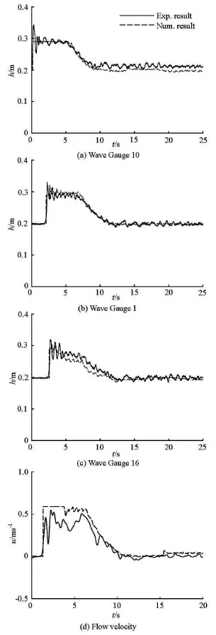
Fig.4 Single pier:Depth and velocity histories at sampling gauges

Fig.5 Single pier:Pressure histories at sampling sensors
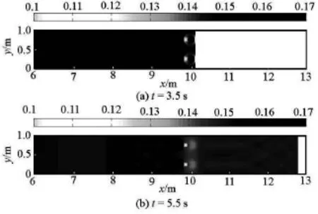
Fig.6 Double piers:Water-structure interaction at sampling output times
3.2 Double-pier test
In order to investigate the wave impacts on different types of structure,a model bridge with double piers is also used in the laboratory experiments.One of the double-pier experiments is selected to further demonstrate the performance of the current numerical model.In order to also consider different flow conditions in the fluid-structure interaction,the dam-break test with an initial still water depth of 0.204 m and 0.105 m upstream and downstream the dam is selected for this numerical simulation,while all other domain and numerical settings keep the same as in the pre-vious single-pier test.

Fig.7 Double piers:Depth and velocity histories at sampling gauges
Figure 6 depicts the plan-view of the water depth at two different output times.Similar to the single-pier test,the dam-break shock front develops following the dam failure at t=0sand travels rapidly to downstream.Due to the shallower initial water depth,the shock wave propagates at a slower speed compared to the single-pier case where the downstream initial depth is 0.198 m.The sharp wave front hits the two bridge piers slightly beforet=3.5s,which immediately results in the formation of two semi-circular reflected shocks propagating upstream towards the reservoir.Att=5.5s,very complex wave patterns are developed following the wave-structure-boundary interaction,as also observed at the single-pier test.
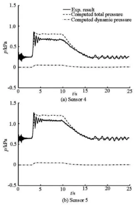
Fig.8 Double piers:Pressure histories at sampling sensors
The comparison between the numerically predicted and experimentally measured time histories of the water depth at the three sampling gauges is presented in Fig.7 and a good agreement is again observed.For the pressure,only two of the pressure sensors at the front side of the bridge pier are initially submerged to give accredited data.Comparison is therefore made between the numerical and experimental data at these two sensors and the results are presented in Fig.8.Similar to the single-pier test,the numerical solutions compare satisfactorily with the measurements except for a slight over-prediction at the peak.From the results,it is also interesting to notice that the wave-structure interaction,as indicated by the time histories of the water depth and the pressure,sees similar processes for both cases being simulated,where the twopier structures seem to receive a similar wave impact as those single-pier structures.However,this conclu-sion may depend on the magnitude of the incoming shock.
4.Conclusions
In this paper,physical experiments are conducted to better understand the physical processes following the impact of the extreme hydrodynamic flow on structures,which may occur following a flood event caused by dam breaks,flash floods,tsunamis or storm surges.Due to the hydraulic similarity between these flood flows and the dam-break waves,the dam-break experiments are designed and carried out in the hydraulic laboratory at Hohai University,China to investgate the extreme flow impact on two types of bridge structures.As observed at the sampling results being shown in Section 3,the impact of the dam-break shock wave on both types of structures indicated by the pressure variation shows a sharp rise following the arrival of the incoming dam-break wave front.The pressure is much larger than that measured under the normal flow conditions and must be properly taken into account in the structural design.
In order to facilitate wider and more flexible applications in hazard management,city planning and structural design,a finite volume Godunov-type model involving the two-dimensional SWEs is validated through applications to reproduce two selected laboratory experiments.The proposed model is used to predict water depth and pressure,and the results closely agree with the laboratory measurements.Particularly,the model can capture accurately the shock-like flow discontinuities following the dam breaks and reliably predict the arriving time of the wave front.The model is further developed to enable the pressure calculation in order to quantify the flood impact on structures and the new model component is also successfully validated in the numerical simulations.Therefore,the model may potentially provide a robust tool for a wide range of field-scale applications and can be also used for calibrating simplified models or formulae for structural design.
Acknowledgment
This work was supported by the Royal Society,as in the International Exchange Program (Royal Society Grant No.IE131297).
[1]DALRYMPLE R.A.,KRIEBEL D.L.Lessons in engineering from the tsunami in Thailand[J].The Bridge,National Academy of Engineering,2005,35(2):4-13.
[2]ROSSETTO T.,PEIRIS N.and POMONIS A.et al.The Indian Ocean tsunami of December 26,2004:observations in Sri Lanka and Thailand[J].Natural Hazards,2007,42(1):105-124.
[3]NISTOR I.,PALERMO D.and CORNETT A.et al.Experimental and numerical modeling of tsunami loading on structures[C].33rd International Conference on Coastal Engineering.Santander,Spain,2012.
[4]KENDON E.J.,ROBERTS N.M.and FOWLER H.J.et al.Heavier summer downpours with climate change revealed by weather forecast resolution model[J].Nature Climate Change,2014,4(7):570-576.
[5]KELMAN I.,SPENCE R.An overview of flood actions on buildings[J].Engineering Geology,2004,73(3):297-309.
[6]PISTRIKA A.K.,JONKMAN S.N.Damage to residential buildings due to flooding of New Orleans after hurricane Katrina[J].Natural Hazards,2010,54(2):413-434.
[7]ROBERTSON I.N.,RIGGS H.R.and YIM S.C.et al.Lessons from Hurricane Katrina storm surge on bridges and buildings[J].Journal of Waterway,Port,Coastal,and Ocean Engineering,2007,133(6):463-483.
[8]WU Jian-song,ZHANG Hui and YANG Rui et al.Numerical modeling of dam-break flood through intricate city layouts including underground spaces using GPU-based SPH method[J].Journal of Hydrodynamics,2013,25(6):818-828.
[9]FRANZ S.,TOBIAS B.and HOU J.et al.A model for overland flow and associated processes within the hydroinformatics modelling system[J].Journal of Hydroinformatics,2014,16(2):375-391.
[10]LIANG Q.,SMITH L.S.A high-performance integrated hydrodynamic modelling system for urban flood simulations[J].Journal of Hydroinformatics,2015,17(4):518-533.
[11]LIANG Q.,DU G.and HALL J.W.et al.Flood inundation modeling with an adaptive quadtree grid shallow water equation solver[J].Journal of Hydraulic Engineering,ASCE,2008,134(11):1603-1610.
[12]GHADIMI P.,REISINEZHAD A.Numerical simulation of flood waves and calculation of exerted forces on the cylindrical piers in contraction channels with different cross section profiles[J].Journal of Hydroinformatics,2012,14(2):366-385.
[13]LIANG Qiuhua.A coupled morphodynamic model for applications involving wetting and drying[J].Journal of Hydrodynamics,2011,23(3):273-281.
[14]LIANG Q.,BORTHWICK A.G.Adaptive quadtree simulation of shallow flows with wet-dry fronts over complex topography[J].Computers and Fluids,2009,38(2):221-234.
[15]GREENBERG J.M.,LEROUX A.Y.A well-balanced scheme for the numerical processing of source terms in hyperbolic equations[J].SIAM Journal on Numerical Analysis,1996,33(1):1-16.
[16]TORO E.F.,SPRUCE M.and SPEARES W.Restoration of the contact surface in the HLL-Riemann solver[J].Shock waves,1994,4(1):25-34.
[17]Van LEER B.Towards the ultimate conservative difference scheme.V.A second-order sequel to Godunov's method[J].Journal of Computational Physics,1979,32(1):101-136.
[18]HU K.,MINGHAM C.G.and CAUSON D.M.Numerical simulation of wave overtopping of coastal structures using the non-linear shallow water equations[J].Coastal Engineering,2000,41(4):433-465.
[19]YIM S.C.Modeling and simulation of tsunami and storm surge hydrodynamic loads on coastal bridge structures[C].Proceedings of the 21st US-Japan Bridge Engineering Workshop.Tsukuba,Japan,2005.
10.1016/S1001-6058(16)60628-5
(Received September 9,2015,Revised December 15,2015)
* Project supported by the National Natural Science Foundation of China (Grant Nos.51379074,51411130125),the Chinese Government “Recruitment Program of Global Experts”.
Biography:Qiuhua LIANG (1974-),Male,Ph.D.,Professor
2016,28(2):267-274

- 水动力学研究与进展 B辑的其它文章
- Manoeuvring prediction based on CFD generated derivatives*
- Calculation of tip vortex cavitation flows around three-dimensional hydrofoils and propellers using a nonlinear k -ε turbulence model*
- Hull form optimization of a cargo ship for reduced drag*
- Numerical simulation of self-similar thermal convection from a spinning cone in anisotropic porous medium*
- An axisymmetric model for draft tube flow at partial load*
- An iterative re-weighted least-squares algorithm for the design of active absorbing wavemaker controller*